LG 3828W5U0492, Installation Instructions Manual
The LG 3828W5U0492 is a versatile product with an easy installation process. Ensure successful setup with our step-by-step Installation Instructions Manual, available for free download on manualshive.com. This comprehensive manual provides all the necessary information you need to get started effortlessly.
Share
Download


Reviews:
No comments
Related manuals for 3828W5U0492
700
Brand: Candy Pages: 14
Convection Grill Combination Microwave
Brand: GE Pages: 6
Monogram ZMC1095 Series
Brand: GE Pages: 8
Monogram ZMC1095 Series
Brand: GE Pages: 36
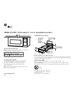
JEM31WF - Spacemaker II Microwave Oven
Brand: GE Pages: 2

Advantium SCA2000BCC
Brand: GE Pages: 3

JE740
Brand: GE Pages: 2

JE1340
Brand: GE Pages: 28

JE1423H
Brand: GE Pages: 31

JEB1095
Brand: GE Pages: 60

JES0737
Brand: GE Pages: 16

JEM25
Brand: GE Pages: 28

JES0738
Brand: GE Pages: 16
JES737
Brand: GE Pages: 16
JES1460DN
Brand: GE Pages: 36
JES1651
Brand: GE Pages: 36
JKP85 Series
Brand: GE Pages: 44
JKP86
Brand: GE Pages: 44


