background image

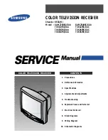
COLOR TV

SERVICE MANUAL

CHASSIS : MC-05HA

MODEL : 32FS2AMB/ANB

MODEL : 

29FS2AMB/ANB-TE

website:http://biz.LGservice.com

e-mail:http://www.LGEservice.com/techsup.html

CAUTION

BEFORE SERVICING THE CHASSIS,
READ THE SAFETY PRECAUTIONS IN THIS MANUAL.

Summary of Contents for 29FS2AMB

Page 1: ...MANUAL CHASSIS MC 05HA MODEL 32FS2AMB ANB MODEL 29FS2AMB ANB TE website http biz LGservice com e mail http www LGEservice com techsup html CAUTION BEFORE SERVICING THE CHASSIS READ THE SAFETY PRECAUTIONS IN THIS MANUAL ...

Page 2: ...FETY PRECAUTIONS 3 CONTROL DESCRIPTIONS 4 SPECIFICATIONS 7 ADJUSTMENT INSTRUCTIONS 8 TROUBLE SHOOTING 17 PRINTED CIRCUIT BOARD 20 BLOCK DIAGRAM 24 EXPLODED VIEW 28 EXPLODED VIEW PARTS LIST 29 REPLACEMENT PARTS LIST 30 SVC Sheet ...

Page 3: ...perform an AC leakage current check on the exposed metallic parts of the cabinet such as antennas terminals etc to be sure the set is safe to operate without damage of electrical shock Leakage Current Cold Check Antenna Cold Check With the instrument AC plug removed from AC source connect an electrical jumper across the two AC plug prongs Place the AC switch in the on position connect one lead of ...

Page 4: ...s menu settings OK accepts your selection or displays the current mode 6 VCR BUTTONS control a LG video cassette recorder 7 I II selects the language during dual language broadcast selects the sound output option 8 PSM Picture Status Memory recalls your preferred picture setting 9 SLEEP sets the sleep timer 10 MAIN STILL freezes motion of the picture 11 TELETEXT BUTTONS option These buttons are us...

Page 5: ...LL freezes motion of the sub picture POSITION relocates the sub picture in clockwise direction 9 4 PIP switches on or off the 9 or 4 sub pictures 21 FAVOURITE selects a favorite programme No function COLOURED BUTTONS These buttons are used for teletext only TELETEXT models or programme edit I II SSM LIST PSM SLEEP MAIN STILL Q VIEW SWAP INPUT SIZE STILL POSITION PR PR EYE INDEX PIP OK PR VOL PR VO...

Page 6: ...em switches the set on from standby 5 REMOTE CONTROL SENSOR 6 AUDIO VIDEO IN SOCKETS AV3 Connect the audio video out sockets of external equipment to these sockets S VIDEO AUDIO IN SOCKETS S AV Connect the video out socket of an S VIDEO VCR to the S VIDEO socket Connect the audio out sockets of the S VIDEO VCR to the audio sockets as in AV3 7 EYE option adjusts picture according to the surrounding...

Page 7: ...ative Humidity 65 10 3 Power voltage 110 240V 50 60Hz 4 Follow each drawing or spec for spec and performance of parts based upon P N of B O M 5 Warm up TV set for more than 20min before the measurement A General Specifications No 1 2 3 4 5 6 7 8 9 10 Specification PAL SECAM BG PAL SECAM DK PAL I SECAM L L NTSC M NTSC M PB PAL BG DK I SECAM BG DK 480i 480P 576i 576P 1080i 50Hz 60Hz 720P 50Hz 60Hz 1...

Page 8: ...input AC voltage of the receiver must keep rating voltage in adjusting 5 The receiver must be operated for about 15 minutes prior to the adjustment 3 Soft ware download 1 Connect JIG to P004 of Digital Board 2 Connect SCL line of JIG Switch to Ground 3 Turn on JIG and supply 6V to Digital Board Terminate the SCL of clause 2 by using Switch 4 After termination of SCL line wait for 3 second 5 Execut...

Page 9: ...of CPT by crossing adjustment At this time 4 6 pole magnet is located to magnet of nothing 5 Move the DY to make equal red on whole screen and it does not to make the DY by fixed screw after check a simple color of Red Green Blue and white raster whether or not it is a pollution of color At this time take care raster of screen and DY must fixing in the condition which maintains a horizontality 6 C...

Page 10: ...1 set 3 Remote control for adjustment 9 2 Preliminary steps 1 Tune the TV set to receive an 100 white pattern 2 This adjustment should be performed after screen voltage adjustment 9 3 Adjustment 1 White Balance should be adjusted with White balance meter and the remote controller 2 Press the ADJ button to enter the adjustment mode search for RGB W B mode with CHD E and select with VOL button 3 Sel...

Page 11: ... 11 ...

Page 12: ...zontal center line of a digital circle pattern is in accord with geometric horizontal center of the CPT HS Horizontal Shift Adjust so that the vertical center line of a digital circle pattern is in accord with geometric vertical center of the CPT EW East West Horizontal Width Adjust outer line of the left right outer lattice to be united with effective boundary surface of CPT BOW In line adjustmen...

Page 13: ... OPTION setting 13 2 Preliminary steps 1 This option adjustment decides function in accordance with model Press the SVC TX adjustment button CH up down button at SVC mode then adjust the option at OPTION1 2 3 4 5 mode 2 Mark the option adjustment data like 111 111 111 111 111 in BOM 13 2 Adjustment Method 1 Input OPTION value with number button on remote control at each OPTION adjustment mode 2 At...

Page 14: ...ux3 0 Others 1 ALL COUNTRIES EXCEPT AUSTRALIA 0 AUSTRALIA ONLY 1 CHINA AUSTRALIA 0 OTHERS 1 ALL 0 1 WITH PIP MODEL 0 WITHOUT PIP MODEL Function Remark Code 1 2 3 4 5 6 7 Option SYS FMTRM A2 ST HDEV VOL WOOF HPHON 0 BG I DK L 1 BG I DK M 2 3 SYSTEM 3 RESERVED 1 WIDE BAND XWAVE 0 NO XWAVE 1 NICAM CHECK FM STEREO DUAL operate 0 NICAM CHECK FM STEREO DUAL not operate 1 HIGH DEVIATION MODULATION 0 RF N...

Page 15: ... Russian Swedish Czech Estonian Lettish English Russian Estonian Czech Ukrainian Lettish English French Swedish Turkish Portuguese German Spanish Italian Greek English Turkish German Greek English French Swedish Turkish German Spanish Italian Greek French English Turkish Arabic English French Turkish Arabic Hebrew Arabic English French Arabic Hebrew English French Turkish Parsi French Turkish Pars...

Page 16: ... 1 no use 0 ALL 1 Limit MAX VOL Level CH EDIT 0 1 no use READY 0 ALL 1 FB90 FC40 index option 0 Other Tool all 1 WITH INDEX MODEL 0 W O INDEX MODEL 1 29FB90 0 Other tool Function Remark Code 00FA 001F FFF2 FFE2 FFD1 FFE0 0003 FFE8 0003 EHTTH EHT S EHTV1 EHTV2 EHTH1 EHTH2 EHT F EHTP 1 EHTP 2 ITEM PAL 100Hz 00FA 001F FFF2 FFE2 FFD1 FFE0 0003 FFE8 0003 NTSC 1080i 50Hz 00FA 001F FFF2 FFF2 FFD1 FFE0 00...

Page 17: ...IC001 191 Waveform of Digital Board IC500 R G B VM OUT0 65 68 Check MAIN R118 Waveform NO Check around each Jack NO Check around IC001 Q004 Q005 NO Check around IC652 NO Check around TU101 NO Check around IC001 Waveform of MAIN1 Tuner SIF YES YES YES Waveform of Digital Board IC001 9 10 11 12 13 14 av1 2 3 R598 R599 Component1 at each MOde YES YES Waveform of MAIN IC652 1 2 L 14 15 R Waveform of D...

Page 18: ... Board IC510 51 52 53 46 YES YES YES NO NO NO NO NO Check around IC001 NO Waveform of Digital Board IC001 195 Waveform of Digital Board IC510 19 22 24 28 YES Waveform of Digital Board IC001 165 167 Check MAIN Board of Power Line NO NO NO NO NO Check ST_3 3 of IC001 45 75 ST_1 8V of IC001 124 169 Replace X001 Replace Q009 Q010 YES YES YES YES Check IC001 79 89 OSC Check IC001 83 84 SCL SDA Check Ab...

Page 19: ...output IC830 IC840 IC843 Check B voltage 125 135V or OPEN Check Replace D1810 0V Check Replace IC810 0V OK NO NO NO YES OK YES YES 0V Check Replace Q422 T402 Is the waveform at Drain Q408 normal 5 No raster Check F1701 Fuse on PSW Board Does the square waveform from PIN 23 of IC500 appear Check the voltage at pin2 of IC801 Check the voltage of C1806 ...

Page 20: ... 20 PRINTED CIRCUIT BOARD MAIN ...

Page 21: ... 21 DIGITAL TOP STAND BY ...

Page 22: ... 22 SIDE A V LED PRE AMP DIGITAL BOTTOM ...

Page 23: ... 23 CPT POWER S W CONTROL ...

Page 24: ... 24 BLOCK DIAGRAM Vertical Vertical 1 MAIN ...

Page 25: ... 25 2 VCT P Video ...

Page 26: ... 26 3 VCT P Audio ...

Page 27: ...MEMO 27 ...

Page 28: ...EXPLODED VIEW 28 112 913 170 150 510 P1802 503 501 550 520 580 120 300 310 530 600 540 331 330 320 590 700 400 943 ...

Page 29: ...MM251G PCB Assembly Main MAIN1 M I MC05HA 32FS2AMB TE ATSLLA 68719MM251H PCB Assembly Main MAIN1 M I MC05HA 32FS2AMB TE ATCLLA 68719MMX66C PCB Assembly MAIN1 M I MC05HA 32FS2ANB TE KMALLEY LGESY 530 68719SM275A PCB Assembly Sub SUB M I MC05HA LOCAL KEY 29FS2 68719SMN06A PCB Assembly SUB M I MC05HA 29FS2ANB TE CONTROL LGESY CKD 540 68719PM264A PCB Assembly POWER M I MC05HA 29FS2ANB TE 174 322G LGES...

Page 30: ... 15A 400NSEC R1 TP TVR06J 600V 1400MV 10UA 25A 300NSEC 1N4148 1V 100V 150MA 500MA 4NSEC 500MW 1N4005 600V 1 1V 5UA 30A 1N4005 600V 1 1V 5UA 30A EK14 550MV 40V 1 5A LOCA NO PART NO DESCRIPTION HIC920 IC001 IC002 IC003 IC007 IC1801 IC1802 IC201 IC202 IC203 IC301 IC401 IC500 IC510 IC511 IC650 IC652 IC801 IC822 IC830 IC843 IC880 IC900 Q001 Q001 Q002 Q003 Q004 Q005 Q008 Q009 Q010 Q011 Q012 Q013 Q013 Q1...

Page 31: ... 105MA LOCA NO PART NO DESCRIPTION C003 C005 C011 C033 C039 C041 C054 C056 C059 C062 C071 C072 C074 C077 C097 C097 C101 C102 C104 C107 C108 C109 C110 C114 C115 C116 C117 C120 C1204 C1208 C121 C1210 C1211 C1212 C1213 C123 C124 C129 C161 C162 C163 C164 C165 C166 C171 C172 C174 C175 C176 C1801 C1802 C1803 0CE107DD618 0CE107DD618 0CE106DF618 0CE105DK618 0CE335DK618 0CE107DF618 0CE107DD618 0CE227SF6DC ...

Page 32: ...100uF 20 50V DCM332K39Y5PL6FJ5A 3 3nF 10 500V Y5P LOCA NO PART NO DESCRIPTION C422 C422 C423 C424 C425 C426 C427 C429 C430 C430 C431 C432 C433 C434 C435 C436 C437 C438 C440 C442 C443 C444 C445 C448 C449 C503 C507 C513 C517 C520 C527 C532 C546 C551 C559 C561 C562 C574 C579 C580 C583 C584 C589 C650 C651 C652 C653 C653 C654 C655 C655 C656 181 011B 181 011C 181 091U 0CF95213CFH 181 010A 0CE685BK652 0C...

Page 33: ...5H17G 10uF 20 250V 120MA DCH472K75Y5PP7DK0A 4 7nF 10 2000V EGR475M250T1G1G11G 4 7uF 20 250V 70MA CH UP050 F104Z B B Z 100nF 20TO 80 EGR107M016T1G1C11G 100uF 20 16V 160MA RH UP050 B151K B B 150pF 10 50V Y5P LOCA NO PART NO DESCRIPTION C908 C910 C911 C920 C921 C922 C923 C924 C925 C926 C927 C928 C929 C930 C932 C933 C935 L101 L102 L1201 L1202 L212 L213 L301 L302 L401 L402 L421 L422 L423 L423 L424 L513...

Page 34: ...62 R088 R101 R102 R103 R104 R105 R107 R108 R109 R110 R111 R112 R115 R116 R117 R118 R119 R120 R1204 R1206 R1208 R1212 R122 R125 R126 R127 R128 R129 R1292 R130 R135 R160 R161 R162 R163 R164 R165 R166 R170 R1701 R171 R172 366 932F 366 921B 387 A05J 0RF0101K607 0RF0121K607 0RD5601F609 0RRZVTA001A 0RRZVTA001A 0RRZVTA001A 0RD2200F609 0RD2200F609 0RD4300A609 0RD0102F609 0RD0102F609 0RD1000F609 0RD1000F60...

Page 35: ...220R 220OHM 5 2W 12 0X4 0MM RD 96T1J100R 100OHM 5 1 6W 3 2X1 8MM RD 96T1J4K70 4 7KOHM 5 1 6W 3 2X1 8MM RS 92T1J330R 330OHM 5 1 2W 9 0X3 0MM PRW02T3KR110 0 11OHM 10 2W 12 0X4 0MM RS 92T1J56R0 56OHM 5 1 2W 9 0X3 0MM RSD02T3J470R 470OHM 5 2W 12 0X4 0MM RDM92T1J1K00 1KOHM 5 1 2W LOCA NO PART NO DESCRIPTION 0RD5100A609 0RD1000F609 0RF0470K607 0RD1001A609 0RF0470K607 0RD1301A609 0RD2701A609 0RD2701A609 ...

Page 36: ...M RD 96T1J6K20 6 2KOHM 5 1 6W 3 2X1 8MM RD 92T1J10K0 10KOHM 5 1 2W 9 0X3 0MM RD 92T1J100K 100KOHM 5 1 2W 9 0X3 0MM LOCA NO PART NO DESCRIPTION R940 R941 R942 RT01 RT02 RT03 RT04 SW06 SW1 SW1701 SW2 SW3 SW4 SW5 SW6 FB101 FB403 L002 L003 L004 L005 L006 L007 L008 L009 L010 L011 L012 L013 L216 L501 L502 L503 L504 L505 L514 L515 L516 L517 L518 L519 L801 L802 L830 L840 L861 L870 L880 0RD3600H609 0RD3600...

Page 37: ...MHZ HC 49 U 5MHZ 30PPM 5MHZ 30PPM HC 49 U 27MHZ 25PPM 27MHZ 25PPM PMJ016D 22P RCA DIN 14 15 5MM PPJ125D 14 0MM 5RX2C ANGLE TR PPJ146 2 14 0MM 3RX3C ANGLE BK Cable Assembly PHONO PLUG PHONO PLUG Fuse Time Delay 0218 005 GLASS 250V 5A LED DIP SA5711 B DL 1LO S ROUND 5mM Receiver Module TSOP2438 4 5TO5 5V 1 5MA S W System Program V2 54 2456 Spark Gap Axial WSA 362M AXIAL 3 6KV Spark Gap Axial SSA 102...

Page 38: ...P No 38549D0023A 1 2 2006 01 20 ...

Page 39: ...P No 38549D0023A 2 2 2006 01 20 ...

Page 40: ...SVC SHEET 38549D0023A S ...

Page 41: ...Apr 2006 Printed in Korea P NO 38289S0046D ...

Reviews: