TECHNICAL EDUCATION
JOB AID
4317405
KAR-18
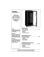
Wine Cellar
Models: KUWS24RSBS
KUWS24LSBS KUWS24RSSS
KUWO24RSBX KUWO24LSBX
Beverage Center
Models: KBCS24RSBS
KBCS24LSBS KBCS24RSSS
KBCO24RSBX KBCO24LSBX
Undercounter Refrigerator
Models: KURS24RSBS
KURS24LSBS KURS24RSSS
KURO24RSBX KURO24LSBX
KitchenAid Undercounter Refrigeration Suite
Summary of Contents for Architect Series II KURO24LSBX
Page 12: ...2 4 NOTES ...
Page 14: ...3 2 NOTES ...
Page 44: ...4 30 NOTES ...
Page 50: ...5 6 NOTES ...
Page 53: ...7 1 WIRINGDiagrams Wine Cellar Wiring Diagram ...
Page 54: ...7 2 Beverage Center Wiring Diagram ...
Page 55: ...7 3 Undercounter Refrigerator Wiring Diagram ...
Page 56: ...7 4 NOTES ...
Page 58: ......