background image

MINIDISC RECORDER

INSTRUCTION MANUAL

DM-5090

B60-3497-00  MA  (M,T,C)  MC
98/12 11 10 9 8 7 6 5 4 3 2 1 97/12 11 10 9 8

Summary of Contents for DM-5090

Page 1: ...MINIDISC RECORDER INSTRUCTION MANUAL DM 5090 B60 3497 00 MA M T C MC 98 12 11 10 9 8 7 6 5 4 3 2 1 97 12 11 10 9 8 ...

Page 2: ... voltage selection The AC voltage selector switch on the rear panel is set to the voltage that prevails in the area to which the unit is shipped Before connecting the power cord to your AC outlet make sure that the setting position of this switch matches your line voltage If not it must be set to your voltage in accordance with the following direction AC voltage selector switch For the United King...

Page 3: ...23 AUTO MANUAL key 23 MONITOR key 23 REC MODE key 24 Recording ANALOG input 26 ANALOG recording 26 Recording DIGITAL input 28 DIGITAL recording 28 Synchro recording with CD playback 30 DIGITAL recording and SCMS 30 Editing 31 Selecting the editing function type 31 Moving the track being played TRACK MOVE 32 Moving several tracks at a time QUICK MOVE 34 Dividing the track being played TRACK DIVIDE ...

Page 4: ...wall outlet Accessory only for regions where use is necessary Remote control unit 1 AC plug adaptor 1 Batteries 2 This unit incorporates the KENWOOD original D R I V E circuit which makes high quality sound reproduction possible D R I V E Dynamic Resolution Intensive Vector Enhancement The sampling rate converter incorporated in this unit is compatible with all digital sources 32 kHz 44 1 kHz 48 k...

Page 5: ...hould not be placed in a built in installation such as a bookcase or rack unless proper ventilation is provided or the manufacturer s instructions have been adhered to 5 Water and moisture The appliance should not be used near water for example near a bathtub washbowl kitchen sink laundry tub in a wet basement or near a swimming pool etc Never pull or stretch the cord 6 Temperature The appliance m...

Page 6: ... of grounding conductors location of antenna discharge unit connection to grounding electrodes and requirements for the grounding electrode See Figure 18 Power lines An outside antenna system should not be located in the vicinity of overhead power lines or other electric light or power circuits or where it can fall into such power lines orcircuits Wheninstallinganoutsideantennasystem extreme care ...

Page 7: ... operations 1 Set the POWER key to ON without loading a Mini Disc Check that no disc is present in the unit 2 Wait a few seconds and verify that the display shown appears 3 Set the POWER key to OFF Storage position Do not leave Mini Discs in place where the temperature and or humidity are extremely high for example in a place subject to direct sunlight Slide close Recording enabled Slide open Reco...

Page 8: ... hours of power failure or slipping out of the power cord the data related to recording and editing that is usually recorded at the moment the Mini Disc is ejected may be cleared or destroyed before it is written in the Mini Disc Remember that the data lost cannot be recovered After recording or editing be sure to eject the Mini Disc so that the recording or editing data can be written in the disc...

Page 9: ...wly developed high efficiency coding technology The ATRAC compresses the music data to about 1 5 the amount of data which would be obtained with conventional technology by cutting off the sound components which do not pose problem in audition even when they are not present This has made it possible to record or play up to 74 minutes Smallsoundnearlarge sound Sound does not af fect the sensitivity ...

Page 10: ...cord can cause malfunctions or damage to the unit Malfunction of microprocessor If operation is not possible or erroneous display appears even though all connections have been made properly reset the microprocessor referring to In case of difficulty p Caution regarding placement To maintain proper ventilation be sure to leave a space around the unit from the largest outer dimensions including proj...

Page 11: ...tem control plugs are inserted all the way in to the system control terminals About the system control operations Remote Control Lets you operate this unit with the system remote supplied with the amp or receiver Automatic Operation Automatically switches the input selector on the amp or receiver when you start playback from this unit Synchronized Recording When recording a CD after setting the am...

Page 12: ...into the unit s internal circuitry to back up the memory This condition is referred to as the standby mode of the unit While the unit is in the standby mode it can be turned ON from the remote control unit Standby mode Names and functions of parts Display Main unit Display TITLE and SEARCH indicators MONO indicator PGM Program indicator Peak level indicators Listening through headphones Plug the s...

Page 13: ... the title input operation PHONES jack Connect stereo headphones optional here PHONES LEVEL knob Rotate to adjust the volume of the headphones 1 Mini Disc insertion slot When a Mini Disc is inserted while the unit is in the standby mode it is turned ON automatically 2 Remote control sensor 3 Manual search down 1 key y This key also functions as the fast reverse key during playback During an editin...

Page 14: ...ges during playback AUTO MANUAL key Selects whether the track numbers are to be marked automatically during re cording AUTO or to be marked manu ally after it MANUAL REC MODE key Press to switch the recording setting ad justment modes REC MODE ON OFF MONITOR key Press to monitor the sound being input from the source while the unit is in stop mode Remote control unit The remote control unit incorpo...

Page 15: ...ended for use in operation checking and their service life may be short 2 When the remote controllable distance becomes short replace both of the batteries with new ones 3 If direct sunlight or the light of a high frequency fluorescent lamp inverter type etc is incident to the remote sensor malfunction may occur In such a case change the installation position to avoid malfunction When pressing mor...

Page 16: ...ural long play mode requires half the amount of data required for stereo mode recording the playing time recording time of the disc is doubled to max 148 minutes from that in the stereo mode A Mini Disc recorded in the monaural long play mode cannot be played normally with equipment which is not compatible with monaural playback In case no disc is loaded When STANDBY is displayed turn the unit ON ...

Page 17: ...ayed Elapsed time of track being played Characters flow toward the left 1 Put the MD recorder in stop mode 2 Enter the track mode PGM goes off Playback of Mini Disc P MODE CHARA OVER dB R L TITLE 0 0 1 T I T L E 15 9 12 7 5 1 3 40 30 21 18 0 SEARCH PGM MONITOR ANALOG 32kHz 2 1 3 48kHz 44 1kHz DIGITAL TITLE SEARCH INPUT JOG DIAL 4 To smaller track No To larger track No 3 7 OVER dB R L TITLE 0 0 3 T...

Page 18: ...212 100 100 0 2 To start playback directly from a part of a track Early part of track No 7 7 2 7 2 Middle part of track No 7 7 5 7 5 Latter part of track No 7 7 8 7 8 Middle part of current track 5 5 If a track NO which does not exist on the disc is selected while READING is blinking the last track on the disc will be played If the PGM indicator is lit press the CHARA P MODE key of the remote cont...

Page 19: ...g playback If forward or reverse search is started during play pause the disc can be searched at a high speed but sound is not output When the reverse search is started during the program mode and the beginning of the current track is attained it will be played from the beginning To stop playback Ejecting the disc Mini Disc has been ejected AUTO PAUSE key When the AUTO PAUSE key is pressed playbac...

Page 20: ...rogrammed period has attained 256 minutes or more Tracks will be played in the order they are programmed When the 4 or key is pressed during playback tracks will be skipped in the direction of the pressed key Total remaining time of the programmed tracks Track No being played The input operation is aborted if the CHARA P MODE key is not pressed while the indicator is blinking PGM lights up Selecte...

Page 21: ...t track in the program after clear is displayed Example when P 14 has been cleared Clearing tracks from the end Press in stop mode Clearing all tracks Press in stop mode Press in stop mode or Programming Remote control unit 1 2 3 4 5 6 7 8 9 100 0 10 ABC DEF MNO JKL GH I PRS TUV WXY QZ P MODE CHARA CHECK CLEAR DELETE CHARACTER SPACE CHECK CLEAR DELETE CHARACTER SPACE P MODE CHARA OVER dB R L COPY ...

Page 22: ... playback Press the REPEAT key again The REPEAT indicator goes off and the playback following the current mode PROGRAM of the MD player starts To stop repeated playback Press the REPEAT key again REPEAT lights up PGM lights up Repeated playback Each press switches the mode 1 Track mode PGM goes off 2 Program mode PGM lights up Each press switches the mode 1 Track mode PGM goes off 2 Program mode P...

Page 23: ... sound blank is not detected When the CD track number is increased during manual search of a CD the track number recorded on the MD may sometimes fail to be incremented A nosound track may sometimes created at the moment the played CD stops MANUAL With this setting the MD track number is not incremented automati cally during recording Track numbers can be marked either during editing by pressing t...

Page 24: ...p 2 Selecting the setting adjustment mode The modes are switched by rotating the JOG DIAL 1 AUTO TIME Setting of the time for detecting a no sound blank section during automatic track num ber marking 2 AUTO LEVEL Setting of the level for detecting a non sound blank section during automatic track number marking 3 REC WRITING Setting of the UTOC writing after recording To change another setting pres...

Page 25: ...ANALOG 32kHz 2 1 3 48kHz 44 1kHz DIGITAL L OVER dB R L 2 E V E L 15 9 12 7 5 1 3 40 30 21 18 0 SEARCH PGM MONITOR ANALOG 32kHz 2 1 3 48kHz 44 1kHz DIGITAL L OVER dB R L F F T I R W 15 9 12 7 5 1 3 40 30 21 18 0 SEARCH PGM MONITOR ANALOG 32kHz 2 1 3 48kHz 44 1kHz DIGITAL N I G O OVER dB R L W R I T G N I N O 15 9 12 7 5 1 3 40 30 21 18 0 SEARCH PGM MONITOR ANALOG 32kHz 2 1 3 48kHz 44 1kHz DIGITAL W...

Page 26: ...LOG or MONO Each press switches the mode 1 ANALOG Analog stereo mode 2 DIGITAL 1 Optical input mode 3 DIGITAL 2 Coaxial input mode 4 MONO Analog monaural long play mode ANALOG lights up 1 Open the write protect tab of the Mini Disc to make it recordable 7 2 Load the Mini Disc 3 Check the remaining recording time ð ł ï i 4 Set the amplifier s input selector to the source to be recorded The modes ar...

Page 27: ...PACE key is pressed during recording a track number is inserted in that position After recording eject the Mini Disc Start recording Information is being written Mini Disc has been ejected Select AUTO or MANUAL Adjust the recording level Main unit only To increase level To decrease level 1 Press the key 2 Play the source to be recorded from the beginning Recording ANALOG input OVER dB MANUAL R L 0...

Page 28: ... amplifier s input selector to the source to be recorded Select AUTO or MANUAL Select one of DIGITAL 1 2 Each press switches the mode 1 REC MODE off 2 REC MODE on AUTO TIME displayed The modes are switched by rotating the JOG DIAL 1 AUTO TIME Setting of the time for detecting a no sound blank section during automatic track num ber marking 2 AUTO LEVEL Setting of the level for detecting a non sound...

Page 29: ...ntained in the digital signal component of the CD Unnecessary track numbers can be erased by following the procedure for Erasing the track being played TRACK ERASE While WRITING is displayed do not apply shock or vibration to the unit because information is being written on the Mini Disc Play the source to be recorded After recording eject the Mini Disc To play a track with a margin from the begin...

Page 30: ... jacks using system control cords the recording of MD can be started in synchronism with the playback of the CD player Note on the sampling rate converter Designed for copyright protection the SCMS is a pre scription that copying of digital signals as they are in the digital form between digital audio equipment is allowable only for one generation Copy using digital input Copy using analog input C...

Page 31: ...ially available recordable Mini Disc the recording can be edited in various ways Note that it is impossible to edit a playback only Mini Disc Editing is not possible while the PGM indicator is lit Moving the track being played TRACK MOVE Moving several tracks at a time QUICK MOVE Reordering tracks by moving them Selecting the editing function type Erasing one or more track at a time QUICK ERASE w ...

Page 32: ...n Select MOVE 1 Select MOVE 2 Set the selection Editing is aborted if no operation has been performed for 8 seconds 1 Play a MD 2 Press the EDIT SPACE key to switch the editing mode on Moving the track being played TRACK MOVE Track being played To increase track No To decrease track No Destination track No Track to be moved OVER dB R L M O V E 15 9 12 7 5 1 3 40 30 21 18 0 SEARCH PGM MONITOR ANALO...

Page 33: ... following key operations before ejecting the disc After canceling the editing operation can be restarted from the beginning Display after execution EDIT NOW When editing is in progress COMPLETE When editing is completed successfully CAN T EDIT When editing is incomplete Mini Disc has been ejected Information is being written Image of track moving Selected destination Selected destination When mov...

Page 34: ...ntrol unit 1 Select a track number 2 Set the selection To increase track No To decrease track No Repeat steps 1 and 2 until all tracks have been arranged in the desired order 20 continuous tracks within the specified range can be reordered at a time 1 Put the MD recorder in stop mode 2 Press the EDIT SPACE key to switch the editing mode on Moving several tracks at a time QUICK MOVE Title scrolling...

Page 35: ...e information is being written on the Mini Disc Display after execution EDIT NOW When editing is in progress COMPLETE When editing is completed successfully CAN T EDIT When editing is incomplete Image of track insertion Display when tracks are moved between two track Nos Display when tracks are moved at the top of all tracks Moved Track Nos Moved Track Nos Moved Track Nos Track No Mini Disc has be...

Page 36: ...till the next track the first track if it is started in the last track but the part in the next track cannot be divided by TRACK DIVIDE Editing is aborted if no operation has been performed for 8 seconds Preparation When preview is not required press the ENTER key once so that ok is displayed then go to step 3 1 Play the MD track to be divided 2 Press the EDIT SPACE key to switch the editing mode ...

Page 37: ... half Divided track first half Should be approx 2 sec or longer Image of track division Image of preview Display after execution EDIT NOW When editing is in progress COMPLETE When editing is completed successfully CAN T EDIT When editing is incomplete While WRITING is displayed do not apply shock or vibration to the unit because information is being written on the Mini Disc Up to 255 track numbers...

Page 38: ...ing played and the track immediately after it will be combined If the operation is started during playback it pauses automatically Preparation To combine the track with the next track to it go to step 3 Track being played To combine track Nos 5 and 7 Combining the track being played TRACK COMBINE 1 Select the track number 2 Set the selection To decrease track No To increase track No Some functions...

Page 39: ...on Should be approx 2 sec or longer Execute the track combine operation Eject the Mini Disc While WRITING is displayed do not apply shock or vibration to the unit because information is being written on the Mini Disc Display after execution EDIT NOW When editing is in progress COMPLETE When editing is completed successfully CAN T EDIT When editing is incomplete Mini Disc has been ejected Informati...

Page 40: ...seconds Display after execution EDIT NOW When editing is in progress COMPLETE When editing is completed successfully CAN T EDIT When editing is incomplete Confirm that the track has been erased Preparation Erasing the track being played TRACK ERASE 1 Select ERASE 2 Set the selection The modes are switched by rotating the JOG DIAL 1 DIVIDE Dividing a track 2 COMBINE Combining tracks 3 ERASE Erasing...

Page 41: ...isc has been ejected While WRITING is displayed do not apply shock or vibration to the unit because information is being written on the Mini Disc Track Nos are adjusted Track to be erased Image of track erasure N O D I S C WRITING EJECT Note Note 0 A B D 1 2 4 3 C A B 1 2 3 D 4 ...

Page 42: ...ase operation 1 Select a track number to be erased 2 Set the selection Selected track SET JOG DIAL 4 SET JOG DIAL 4 OVER dB R L E R Q A S E 15 9 12 7 5 1 3 40 30 21 18 0 SEARCH PGM MONITOR ANALOG 32kHz 2 1 3 48kHz 44 1kHz DIGITAL OVER dB R L o k 15 9 12 7 5 1 3 40 30 21 18 0 SEARCH PGM MONITOR ANALOG 32kHz 2 1 3 48kHz 44 1kHz DIGITAL OVER dB R L 5 B C A 0 0 15 9 12 7 5 1 3 40 30 21 18 0 SEARCH PGM...

Page 43: ...CEL operation is not possible If DISC ERROR is displayed with a Mini Disc which has been know to be normal re load the Mini Disc before pro ceeding to the ALL ERASE operation This may makes it possible to read the Mini Disc contents Display after execution EDIT NOW When editing is in progress COMPLETE When editing is completed successfully CAN T EDIT When editing is incomplete Erasing desired trac...

Page 44: ...n has been performed for 8 seconds To edit a disc title Select DISC To edit a track title Select the desired track number To edit the preset titles Select the desired preset number To erase both disc and track titles 2 Set the selection To abort operation press the TITLE INPUT key again To input a title go to step 2 To change or delete a title go to step 3 Editing titles Main unit Remote control u...

Page 45: ...the 1 and keys Pressing the TITLE SEARCH key during title input switches the input mode between the overwrite mode and insert mode Selected character This procedure is continued on next page 3 Set the selected character Repeat steps 1 to 3 till all of the title charac ters have been input Pressing the EDIT SPACE key inserts a blank space character Main unit Remote control unit A B C D E F E E E E ...

Page 46: ... character 5 Set the selected character The display can be scrolled so that any character in a single group can be selected Characters can also be selected directly from the remote control unit by using the numeric keys Example Each press of the 2 key switches characters in order of A B C The cursor can be moved to the left and right with the 1 and keys All characters of a title can be changed or ...

Page 47: ...nformation is being written on the Mini Disc Scrolling the display There may be cases in which the amount of information is too large to be displayed at a time during the title input operation etc In such a case pressing and holding the 1 or key allows to move the displayed characters to the left or right so that other information which has been hidden can be displayed This leftward or rightward m...

Page 48: ...emaining recording time of disc 3 REMAIN The Mini Disc title is displayed The level meter display contents can be switched over in cycle 1 Normal display The scale around 0 dB is set finely in this mode which is suitable for normal recording rock or playback pop music 2 Wide display The scale is set almost evenly from 0 dB to 30 dB in this mode which is suitable for playing music with wide level v...

Page 49: ...arations For timer recording be sure to set the write protect tab to enable recording 7 For timer recording be sure to check the remaining recording time i 2 5 After having set the timer be careful not to press the ON STANDBY key of the remote control unit to ON otherwise the timer operation would be activated Set the timer so that the tuner reception can be started at the desired time of the day ...

Page 50: ...iting operation may sometimes be impossible to be combined with another track As recording is performed on a minimum recording basis of 2 seconds the displayed time may not coincide with the consumed disc capacity Sound interruption may occur due to a combination of various factors and it is not a malfunction A short track may be created depending on the contents of the recorded source CD for exam...

Page 51: ...ting Release the WRITE PROTECT condition 7 Load a recordable Mini Disc 9 This unit is not loaded with disc The digital cord or optical fiber cable is not locked in position or connected incompletely or not connected An attempt is made to record digital signal from a source while its digital copy has been prohib ited by SCMS The digital signal being input is not an audio signal There is no recordab...

Page 52: ...ted by SCMS The recording level is too low in case of analog recording A playback only disc has been loaded The disc does not have a recordable area The REC INPUT key is not set to the actual input source If the amplifier is connected to this unit through a system control cord the amplifier s input selector is set to the MD input The recording level has not been adjusted A disc in which distorted ...

Page 53: ...namic range playback mode More than 94 dB Wow flutter Less than unmeasurable limit Analog input sensitivity input impedance 500 mV 22 kΩ or more Analog output level output impedance 2 0 V Less than 300 Ω Headphone output 20 mW 32 Ω load Digital input Coxaial 0 5 Vp p 75 Ω Optical Wave length 660 nm 15 dBm 21 dBm Digital output Coxaial 0 5 Vp p 75 Ω Optical Wave length 660 nm 15 dBm 21 dBm General ...

Page 54: ...on This equipment may cause harmful interference to radio communications if it is not installed and used in accordance with the instructions However there is no guarantee that interference will not occur in a particular installation If this equipment does cause harmful interference to radio or television reception which can be determined by turning the equipment off and on the user is encouraged t...

Page 55: ...DM 5090 En 55 MEMO ...
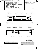
Page 56: ...found on the back of the unit in the spaces designated on the warranty card and in the space provided below Refer to the model and serial numbers whenever you call upon your dealer for information or service on this product Model Serial Number ...

Reviews: