Kenwood CK 231 DF, Instructions For Use Manual
The Kenwood CK 231 DF is a versatile and user-friendly kitchen appliance that will transform your cooking experience. To help you make the most of this product, we offer a comprehensive Instructions For Use Manual that you can download for free from our website. Discover the true potential of your Kenwood CK 231 DF today!
Share
Download


Reviews:
No comments
Related manuals for CK 231 DF

AC60DOSSC
Brand: Sovereign Pages: 12

700 Series
Brand: KBS Gastrotechnik Pages: 69

30"
Brand: Zline Pages: 29

5035
Brand: o.m.s. Pages: 14
ELS110DFF
Brand: Rangemaster Pages: 48

T3
Brand: Eco Range Pages: 12

S100
Brand: Jenn-Air Pages: 36
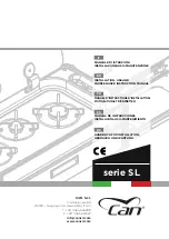
SL Series
Brand: CAN Pages: 362

CE150
Brand: Jata Pages: 24
S9
Brand: La Germania Pages: 44

LPG4920 Series
Brand: Bartscher Pages: 27

Base Camp
Brand: Campingaz Pages: 48

Professional 60
Brand: Cannon Pages: 40

ER30D
Brand: Dacor Pages: 4
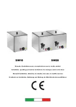
SW10
Brand: Gastrodomus Pages: 12
Classic 110 Dual Fuel
Brand: Falcon Pages: 44
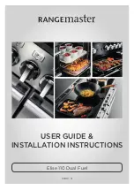
Elan 110 Dual Fuel
Brand: Falcon Pages: 41

Classic 110
Brand: Rangemaster Pages: 32


