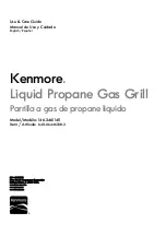
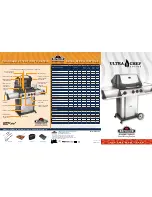
background image

Use & Care Guide 

Manual de Uso y Cuidado 

English / Español 


Kenmore

®


Liquid Propane Gas Grill 

Parrilla a gas de propane liquido 


Models/Modelos:  148.16156211-Black 

                              148.20126510-Stainless Steel 

Items / Artículos:   640-03838924-3-Negro 

640-08668911-4-Acero Inoxidoble


P/N S3218N-Manual 
Sears Brands Management Corporation 

Hoffman Estates, IL    60179 U.S.A. 
www.kenmore.com 

www.sears.com 
www.kmart.com 


®


Summary of Contents for 148.16156211

Page 1: ...rrilla a gas de propane liquido Models Modelos 148 16156211 Black 148 20126510 Stainless Steel Items Artículos 640 03838924 3 Negro 640 08668911 4 Acero Inoxidoble P N S3218N Manual Sears Brands Management Corporation Hoffman Estates IL 60179 U S A www kenmore com www sears com www kmart com ...

Page 2: ...y electrical cords and or fuel supply hoses away from any hot surfaces This grill is safety certified for use in the United States and or Canada only Do not modify for use in any other location Modification will result in a safety hazard Safety Symbols The symbols and boxes shown below explain what each heading means Read and follow all of the messages found throughout the manual If you smell gas ...

Page 3: ...vered repairs Product replacement up to 1500 if your covered product can t be fixed Discount of 25 from regular price of service and related installed parts not covered by the agreement also 25 off regular price of preventive maintenance check Fast help by phone we call it Rapid Resolution phone support from a Sears representative Think of us as a talking owner s manual Once you purchase the Repai...

Page 4: ...allation not performed by Sears authorized service agents including installation that was not in accord with electrical gas or plumbing codes 5 Damage to or failure of this appliance including discoloration or surface rust if it is not correctly operated and maintained according to all supplied instructions 6 Damage to or failure of this appliance including discoloration or surface rust resulting ...

Page 5: ...cylinder must be arranged for vapor withdrawal and include collar to protect LP cylinder valve Always keep LP cylinders in upright position during use transit or storage LP Liquefied Petroleum Gas LP gas is nontoxic odorless and colorless when produced For Your Safety LP gas has been given an odor similar to rotten cabbage so that it can be smelled LP gas is highly flammable and may ignite unexpec...

Page 6: ...soap and water solution Brush soapy solution onto areas indicated by arrows in figure below Leaks are indicated by growing bubbles Do not use household cleaning agents Damage to gas train components valve hose regulator can result Connecting Regulator To The LP Tank 1 LP tank must be properly secured onto grill Refer to assembly section 2 Turn all control knobs to the OFF position 3 Turn LP tank O...

Page 7: ...bles are shown in picture below 5 If growing bubbles appear there is a leak Close LP tank valve immediately and retighten connections If leaks cannot be stopped do not try to repair Call Sears for replacement parts at 1 800 4 MY HOME 6 Always close LP tank valve after performing leak test by turning hand wheel clockwise Hold coupling nut and regulator as shown for proper connection to LP tank valv...

Page 8: ... lid during lighting 3 Open LP cylinder or natural gas valve 4 Push any burner control knob in and turn the knob to the left to HI position Keep pressing the knob until the burner is lit For Safe Use of Your Grill and to Avoid Serious Injury Do not let children operate or play near grill Keep grill area clear and free from materials that burn Do not block holes in sides or back of grill Check burn...

Page 9: ...if no click or spark Valve Check Important Make sure gas is off at LP cylinder before checking valves Knobs lock in OFF position To check valves first push in knobs and release knobs should spring back If knobs do not spring back replace valve assembly before using grill Turn knobs to LOW position then turn back to OFF position Valves should turn smoothly Hose Check Before each use check to see if...

Page 10: ... or replace parts of burner assembly or if you have trouble igniting grill 1 Turn gas off at control knobs and LP cylinder 2 Remove cooking grates and heat diffusers 3 Remove R pins from rear of burners 4 Carefully lift each burner up and away from valve openings We suggest three ways to clean the burner tubes Use the one easiest for you A Bend a stiff wire a light weight coat hanger works well in...

Page 11: ... Meat and Poultry Hotline at 1 800 535 4555 In Washington DC 202 720 3333 10 00 am 4 00 pm EST How To Tell If Meat Is Grilled Thoroughly Meat and poultry cooked on a grill often browns very fast on the outside Use a meat thermometer to be sure food has reached a safe internal temperature and cut into food to check for visual signs of doneness Whole poultry should reach 180 F breasts 170 F Juices s...

Page 12: ...res grill meats with hood open Close hood if meats are thick or weather is cold or if you are using a rotisserie or indirect cooking Always protect your hand with a pot holder or cooking glove when coming into contact with a hot surface Hood up when grilling meats especially chicken Hood down when indirect or rotisserie cooking NEVER leave your grill unattended while cooking After use close hood t...

Page 13: ... TO REDUCE THE RISK OF FIRE ELECTRIC SHOCK EXPOSURE TO EXCESSIVE UV RADIATION OR INJURY TO PERSONS 1 Lighted lamp is HOT Turn off unplug and allow to cool before replacing bulb 2 Bulb gets HOT quickly Only contact switch plug when turning on 3 Do not touch hot lens or bulb fixture 4 Do not look directly at lighted bulb 5 Keep bulb away from materials that may burn 6 Use only with 10 watt or smalle...

Page 14: ...w to cool before putting on or taking off parts 3 Do not operate any outdoor cooking gas appliance with a damaged cord plug or after the appliance malfunctions or has been damaged in any manner Contact the manufacturer for repair 4 Do not let the cord hang over the edge of a table or touch hot surfaces 5 Do not use an outdoor cooking gas appliance for purposes other than intended 6 When connecting...

Page 15: ...ctions including the stem of the shut off valve and the opening of the socket For best results use an ammonia free soap water solution Operating Instructions 1 To connect push back socket sleeve 2 Insert plug and release sleeve 3 Push plug until sleeve snaps forward Gas will flow automatically Failure to connect plug properly to socket will inhibit gas flow to the appliance To disconnect 1 Pull Sl...

Page 16: ...40 1 LP GAS PRESSURE REGULATOR L3218 00 8006 41 1 MAIN BURNER HOSE P3018 00 8021 42 1 MANIFOLD S3218ANR 00 3200 Key Qty Description Manufacturer Part 43 1 SWITCH E3520 00 8015 44 1 REAR BURNER BEZEL L3218 00 3002 45 1 REAR BURNER KNOB L3218 00 3001 46 1 IGNITION WIRE S3218ANR 00 8001 47 1 1 CONTROL BOX BLACK S3218ANB 00 3101 47 2 1 CONTROL BOX STAINLESS STEEL S3218NS 00 3101 48 1 BEAM S3218AR 00 1...

Page 17: ... 7 8 10 11 12 13 14 15 16 18 19 21 22 23 24 25 26 27 29 30 32 33 34 35 36 37 38 40 41 42 43 44 45 46 51 52 54 55 57 59 61 62 60 64 63 1 66 68 48 49 58 28 9 65 1 65 2 67 1 67 2 47 1 47 2 17 1 20 1 31 1 31 2 70 17 2 20 2 56 69 53 50 ...

Page 18: ... placing grill head on cart in Step 13 Open grill lid and remove all packaged parts and packing material WARNING Assemble and place the grill on a flat level surface Compare the parts and hardware with the list and diagrams Do not attempt assembly if any part is missing or damaged Use the supplied wrench to attach the casters to the bottom panel as shown below Attach the two locking casters at the...

Page 19: ...shown Attach side panels to bottom panel as shown For each side panel there are three screws for the rear panel and three for the bottom panel Insert the three bottom panel screws first 1 4 20 x 5 8 Screw Qty 4 Rear Panel Bottom Panel Right Panel Rear Panel Left Panel Bottom Panel ...

Page 20: ... each as shown Slide the tank ring bracket onto the end of the tank ring as shown Attach the bracket to the rear panel with 2 screws as shown Tank Ring Rear Panel Tank Ring Bracket 1 4 20 x 5 8 Screw Qty 6 1 4 20 x 5 8 Screw Qty 2 Left Panel Right Panel Bottom Panel Side Panel Bracket ...

Page 21: ...s shown Remove the cap and the nut from the igniter Secure the igniter and the igniter protective box to side panel with the nut Then reassemble the cap to the igniter 1 4 20 x 5 8 Screw Qty 4 Front Beam Left Panel Right Panel Igniter Igniter protective box Nut Cap ...

Page 22: ...the front beam and rear panel with 4 screws as shown NOTE Drip cup support tabs connect to outside of front beam Put the drip cup on the drip cup support as shown 1 4 20 x 5 8 Screw Qty 4 Drip Cup Support Front Beam Rear Panel Drip Cup ...

Page 23: ... rear panel with 4 each 5 32 32x3 8 screws and nuts Install the LP tank exclusion rods plain end to the bottom panel and nut end to the rear panel LP Tank Exclusion Rod 1 4 20 x 5 8 Screw Qty 4 5 32 32 x 3 8 Screw Qty 4 5 32 Nut Qty 4 ...

Page 24: ...outside the cart and that regulator and igniter wires hangs inside the cart Attach head to cart with 4 screws as shown Loosen the four screws attached to the left panel of the burner box 3 to 4 turns as shown Hang the side shelf by the slotted holes in its side onto the four loosened screws Open the grill lid and use the 1 4 20 x 1 1 4 screw to fasten the side shelf from the inside of the burner b...

Page 25: ...shown Tighten the four previously loosened screws Side Burner Shelf Loosen and remove the two screws holding side burner in place Align the 2 bezel screw holes to those in side burner control panel Insert the valve control stem through the hole in control panel and bezel Attach bezel to control panel and valve control stem with 2 screws as shown Press Knob onto side burner valve control stem 1 4 2...

Page 26: ...step 16 Place the side burner drip tray into position as shown Side Burner Ignition Wire The side burner ignition wire has two connectors Plug the wider connector into one of the two wider sockets in the igniter Plug the narrower connector into the side burner valve as shown Connect here Connect here Ignition wire 5 32 32 x 3 16 Screw Qty 2 Side Burner Shelf Side Burner Nozzle Side Burner drip tra...

Page 27: ...ckets in the igniter as shown Other Ignition Wires Plug the six remaining narrow wire connectors into the remaining narrow igniter sockets and plug the remaining wide connector into the remaining wide igniter socket Also connect light wire to transformer as shown on page 13 Ignition pin wire Ignition pin wire Connect here ...

Page 28: ...ith doors and then tighten magnet screws Open the grill hood cut the zip tie which hold the drip tray with the main burner Adjust the drip tray until it is in the middle bottom of the fire box and hold in place It is an easy clean tray it can be slide out from the back for cleaning Warning Please make sure the drip tray and drip cup are properly installed when burners are on Right Door Left Door 2...

Page 29: ...ming rack as shown NOTE The diffuser edges fit into slots at front and back of burner box The rectangular hole in cooking grate goes to the front Remove battery cap and insert AA battery with positive pole facing out Replace cap LP Tank Installation Open front doors of cart Set base of tank into cart with tank collar opening facing to the right as shown Connect regulator to tank see page 5 of Use ...

Page 30: ...racket Lift back of main burners while sliding burners out of firebox disengaging main burners from valves Fig 1 2 Insert the provided orifice removal tool B into burner openings and unscrew orifices from ends of valves Fig 2 Model Main burner 1 37mm Side burner 1 37mm Rear burner 1 33mm 148 16156211 148 20126510 5 pc Provided in 10478 Kit 1 pc Provided in 10478 Kit 1 pc Provided with grill Orific...

Page 31: ...hich is marked 1 37 Fig 3 4 Rotate the air shutter opening from the LP setting to the NG setting LP 1 4 open NG 1 6 to 1 8 open Fig 4 Side Burner Conversion 1 Remove 2 screws 5 32 32x3 16 in from the end of the side burner valve Fig 5 2 Use a wrench to remove the orifice between the side burner hose and the orifice nut Fig 6 5 32 32x3 16 in screw Fig 5 Hose Orifice nut Orifice Fig 6 1 37 Fig 3 B A...

Page 32: ...2 in at the back of burner box to detach the rear burner cover from the rear panel of burner box During this process hold the rear burner cover otherwise it will drop and may break possibly causing injury Fig 8 2 Use wrench to remove rear burner orifice from the rear burner and the hose Fig 9 Rear burner cover Fig 8 Rear burner Hose Orifice Fig 9 1 37 Fig 7 ...

Page 33: ...is at its rightmost position and the distance is about 0 67 inch and in NG model the air shutter should be at its leftmost position and the distance is about 0 4 inch Please use a screwdriver to adjust the distance After adjustment tighten the screw Fig 11 Natural Gas Hose Connection 1 Remove the LP gas hose and regulator using a wrench and attach the natural gas hose in it s place Fig 12 Rear bur...

Page 34: ...crew in the valve hole using the flathead screwdriver Turn screws two complete turns counterclockwise Fig 13 2 Press all the knobs back onto valve stems 3 After all the conversions are complete return heat diffusers to firebox followed by the grates and warming rack Valve hole Fig 13 ...

Page 35: ...tery 5 Change the battery polarity 6 Reinstall the electrode 7 Turn on the regulator valve 8 Loosen the air shutter and adjust the opening to a smaller size Burner flame is yellow and gas odor can be smelled 1 The air shutter opening is not properly set 2 Spiders or insects block the air shutter 3 Gas leaks 1 Loosen the air shutter and adjust the opening to have blue flames 1 4 in opening for LPG ...

Page 36: ...s run out 1 This model is set for 7 in natural gas usage Please check your natural gas supply system to have correct gas pressure Regulator is not needed for NG model Check the orifice if you installed NG nozzles 2 Clear ports of any obstructions 3 Refill the LP tank Low heat natural gas Gas pressure is significantly affected by gas line and length of gas line from house gas line Check your gas li...

Page 37: ...ow valve tripped 3 Vapor lock at coupling nut LP cylinder connection 1 Check for gas in LP cylinder 2 Turn off knobs wait 30 seconds and light grill If flames are still low turn off knobs and LP cylinder valve Disconnect regulator Reconnect regulator and leak test Turn on LP cylinder valve wait 30 seconds and then light grill 3 Turn off knobs and LP cylinder valve Disconnect coupling nut from cyli...

Page 38: ...nserve los cables eléctricos y o las mangueras de suministro de combustible alejadas de las superficies calientes Esta parrilla tiene certificación de seguridad para uso en Estados Unidos y o Canadá únicamente No modifique para utilizar en cualquier otra ubicación La modificación constituirá un riesgo a la seguridad Símbolos de seguridad Los símbolos y recuadros que aparecen a continuación explica...

Page 39: ...o puede arreglarse Descuento del 25 del precio regular del servicio y las piezas relacionadas instaladas no amparadas por el acuerdo también 25 de descuento sobre el precio regular de las revisiones preventivas de mantenimiento Ayuda telefónica rápida la llamamos Resolución Rápida apoyo telefónico de un representante Sears Piense en nosotros como un manual de servicio parlante Una vez que haya adq...

Page 40: ... generen por la instalación que no hayan hecho agentes de servicio autorizados por Sears incluyendo instalaciones que no cumplan con las normas eléctricas gas o plomería 5 Daños o fallas de este equipo como decoloración u oxidación de la superficie si no se opera y se le hace mantenimiento de manera correcta de acuerdo a todas las instrucciones suministradas 6 Los daños o fallas de este equipo com...

Page 41: ...ipo de válvula El cilindro LP deberá estar acondicionado para salida de vapor e incluir un anillo para proteger la válvula LP del cilindro Siempre conserve los cilindros LP en posición vertical durante el uso tránsito o almacenaje LP Liquefied Petroleum Gas LP gas is nontoxic odorless and colorless when produced For Your Safety LP gas has been given an odor similar to rotten cabbage so that it can...

Page 42: ...y una solución de 50 50 detergente suave y agua Aplique la solución jabonosa en las áreas que indican las flechas de la figura Las fugas se identifican mediante burbujas crecientes No utilice agentes limpiadores domésticos Podrían causar daños a los componentes y tuberías de gas válvula manguera regulador Cómo conectar el regulador al tanque de LP 1 El tanque de LP deberá estar adecuadamente fijad...

Page 43: ...a ilustración 5 Si aparecen burbujas que crecen hay una fuga Cierre la válvula del tanque de LP inmediatamente y vuelva a apretar las conexiones Si no puede detener las fugas no trate de repararlas Llame a Sears para pedir piezas de repuesto al 1 800 4 MY HOME 6 Siempre cierre la válvula del tanque de LP después de realizar la prueba de fugas girando la rueda manual en el sentido horario Sostenga ...

Page 44: ... 4 Presione hacia adentro cualquier perilla de control del quema dor y gire la perilla hacia la izquierda a la posición HI Continúe presionando la perilla hasta que el quemador se encienda Apagar los incendios que produce la grasa cerrando la tapa no es posible Las parrillas están bien ventiladas por razones de seguridad No utilice agua en un incendio ocasionado por la grasa Podrían ocurrir lesion...

Page 45: ...rilla de control hacia adentro y gire la perilla hacia la izquierda a la posición HI Debe escuchar un clic y ver una chispa cada vez entre la caja colectora o el quemador y el electrodo Refiérase a Solución de problemas si no escucha un clic ni ve una chispa Revisión de la válvula Importante Cerciórese de que el gas esté apagado en el cilindro de LP antes de revisar las válvulas Las perillas tranc...

Page 46: ... limpiar y o reemplazar las piezas del ensamble del quemador o si tiene problemas para encender la parrilla 1 Apague el gas en las perillas de control y en el cilindro de LP 2 Retire las rejillas de cocción y los difusores de calor 3 Retire los pasadores R de los quemadores traseros 4 Levante cuidadosamente cada quemador hacia arriba y aléjelo de las aberturas de la válvula Sugerimos tres formas d...

Page 47: ...da USDA sobre carne y aves al 1 800 535 4555 en Washington DC 202 720 3333 10 00 am 4 00 pm hora del este Cómo saber si la carne está totalmente asada La carne y las aves cocinadas a la parrilla a menudo se doran muy rápido por fuera Use un termómetro de carnes para cerciorarse de que el alimento haya alcanzado una temperatura interna segura y haga cortes para observar señales visibles de cocción ...

Page 48: ...ta Cierre la cubierta si la carne es gruesa el clima es frío o usa un rostizador o el método de cocción indirecta Siempre protéjase la mano con una agarradera o guante para cocinar al tomar contacto con una superficie caliente Suba la cubierta al asar carnes especialmente pollo Baje la cubierta al usar el método de cocción indirecta o un rostizador NUNCA deje la parrilla sin supervisión durante la...

Page 49: ...POSICIÓN A RADIACIÓN EXCESIVA POR RAYOS UV O LESIONES A LAS PERSONAS 1 La bombilla se CALIENTA cuando está encendida Apague desenchufe la lámpara y permita que se enfríe antes de reemplazar la bombilla 2 La bombilla se CALIENTA rápidamente Al encenderla toque sólo el interruptor o el enchufe 3 No toque las micas calientes ni la bombilla de la lámpara 4 No mire directamente hacia la bombilla encend...

Page 50: ...piezas 3 No opere ningún electrodoméstico de cocción a gas para exteriores que tenga un cable o enchufe dañados o si el electrodoméstico ha funcionado incorrectamente o sufrido algún tipo daño Póngase en contacto con el fabricante para repararlo 4 No permita que el cable cuelgue del borde de una mesa o toque las superficies calientes 5 No utilice un electrodoméstico de cocción a gas para exteriore...

Page 51: ...ura del socket Para obtener mejores resultados utilice una solución de jabón sin amoníaco y agua Instrucciones de funcionamiento 1 Para conectar presione hacia atrás el manguito del socket 2 Inserte el tapón y libere el manguito 3 Presione el tapón hasta que el manguito encaje adelante El gas fluirá automáticamente No conectar el tapón al socket de forma adecuada podría impedir que el gas fluya ha...

Page 52: ...ULADOR DE PRESIÓN DE GAS PL L3218 00 8006 Clave Cant Descripción Pieza del fabricante 41 1 MANGUERA DEL QUEMADOR PRINCIPAL P3018 00 8021 42 1 TUBO COLECTOR S3218ANR 00 3200 43 1 INTERRUPTOR E3520 00 8015 44 1 BISEL DEL QUEMADOR POSTERIOR L3218 00 3002 45 1 PERILLA DE QUEMADOR POSTERIOR L3218 00 3001 46 1 CABLE DE ENCENDIDO S3218ANR 00 8001 47 1 1 CAJA DE CONTROL NEGRO S3218ANB 00 3101 47 2 1 CAJA ...

Page 53: ...4 5 6 7 8 10 11 12 13 14 15 16 18 19 21 22 23 24 25 26 27 29 30 32 33 34 35 36 37 38 40 41 42 43 44 45 46 51 52 54 55 57 59 61 62 60 64 63 1 66 68 48 49 58 28 9 65 1 65 2 67 1 67 2 47 1 47 2 17 1 20 1 31 1 31 2 70 17 2 20 2 56 69 53 50 ...

Page 54: ...cartón hasta que la coloque en el carro como lo indica el paso 13 Abra la tapa de la parrilla y retire todas las piezas embaladas y el material de embalaje ADVERTENCIA Ensamble y coloque la parrilla sobre una superficie plana y nivelada Compare las piezas y los aditamentos con la lista y los diagramas No intente ensamblar el producto si faltan piezas o si éstas están dañadas Alinee las ruedas con ...

Page 55: ... como se muestra Hay tres tornillos por cada panel lateral para el panel posterior y tres para el panel inferior Inserte primero los tres tornillos del panel inferior Tornillo de 1 4 20 x 5 8 Cant 4 Tornillo de 1 4 20 x 5 8 Cant 12 Panel posterior Panel inferior Panel derecho Panel posterior Panel izquierda Panel inferior ...

Page 56: ...o como se muestra Deslice el soporte del anillo del tanque hacia el extremo del anillo del tanque como se muestra Fije el soporte al panel posterior con 2 tornillos como se muestra Aro del tanque Panel posterior Soporte de aro del tanque Tornillo de 1 4 20 x 5 8 Cant 2 Panel izquierda Panel derecho Panel inferior Soporte del panel lateral ...

Page 57: ...e la tapa y la tuerca del encendedor Fije el encendedor y la caja protectora del encendedor al panel lateral con la tuerca Luego vuelva a colocar la tapa en el encendedor Tornillo de 1 4 20 x 5 8 Cant 4 Barra frontal Panel izquierda Panel derecho Encendedor Encendedor de protección caja Tuerca Tapa ...

Page 58: ...illos como se muestra NOTA Las lengüetas del soporte de la bandeja de goteo se conectan con la parte exterior de la viga frontal Poner el goteo goteo taza taza en el apoyo como se muestra Soporte de la bandeja de goteo Barra frontal Panel posterior Tornillo de 1 4 20 x 5 8 Cant 4 Bandeja de goteo ...

Page 59: ...el posterior con 4 tornillos y tuercas de 5 32 32x3 8 Instale las varillas de exclusión del tanque de PL el extremo simple al panel inferior y el extremo de la tuerca al panel posterior Tornillo de 1 4 20 x 5 8 Cant 4 Tornillo de 5 32 32 x 3 8 Cant 4 5 32 Tuerca Cant 4 ...

Page 60: ...or lateral cuelgue fuera del carrito y que el regulador y los cables del encendedor cuelguen dentro del carrito Fije la parte principal al carrito con 4 tornillos como se muestra Dé 3 a 4 vueltas para aflojar los cuatro tornillos fijados en el panel izquierdo de la caja del quemador Cuelgue las ranuras laterales por los orificios ranurados en sus costados sobre los cuatro tornillos aflojados Abra ...

Page 61: ... Estante del quemador lateral Suelte y retire los dos tornillos que sostienen el quemador lateral en su lugar Alinee los dos orificios de los tornillos de bisel a aquellos dentro del panel de control del quemador Inserte el vástago de la válvula de control por el orificio del panel de control y el bisel Fije el bisel al panel de control y al vástago de la válvula de control con 2 tornillos como se...

Page 62: ... la bandeja de goteo del quemador lateral en la posición que se muestra Cable de encendido del quemador lateral El cable de encendido del quemador lateral tiene dos conectores Enchufe el cable conector en uno de los dos tomacorrientes más anchos del encendedor Asegure el conector más angosto en la válvula del quemador lateral como se muestra Conecte aquí Conecte aquí Cable de encendido Tornillo de...

Page 63: ...r como se muestra Otros cables de encendido Enchufe los seis conectores de cables angostos restantes en el tomacorriente del encendedor angosto restante y enchufe el conector ancho restante en el tomacorriente del encendedor ancho restante También conecte el cableado de la luz al transformador como se muestra en la página 49 Cable del encendido pasador Cable del encendido pasador Conecte aquí ...

Page 64: ...Abra la tapa de la parrilla corte el alambre plastificado que sujeta la bandeja de goteo con el horno principal Ajuste la bandeja de goteo hasta que esté en la parte inferior central de la caja de fuego y manténgala en su lugar La bandeja de goteo es fácil de limpiar se puede deslizarla hacia afuera de la parte trasera para la limpieza Advertencia Por favor asegúrese de que la bandeja de goteo y l...

Page 65: ...rificio rectangular de la rejilla de cocción va en la parte frontal Retire la tapa de la batería e inserte las baterías AA con el polo positivo orientado hacia fuera Vuelva a colocar la tapa Instalación del tanque de PL Abra las puertas frontales del gabinete Coloque la base del tanque en el gabinete Conecte el regulador al tanque refiérase a la página 41 de la sección de uso y cuidado Rejilla par...

Page 66: ...emadores principales mientras los desliza hacia fuera de la cámara de combustión soltándolos de las válvulas Fig 1 2 Inserte la herramienta para eliminar orificios B proporcionada en las aberturas del quemador y desatornille los orificios de los extremos de las válvulas Fig 2 Modelo Quemador principal 1 37mm Quemador lateral 1 37mm Quemador posterior 1 33mm 148 16156210 148 16157210 5 pcs Dispuest...

Page 67: ...ire la abertura del obturador de aire del ajuste de PL al ajuste de GN PL Abertura de 6 35 mm GN Abertura de 4 23 mm a 3 18 mm Fig 4 Conversión del quemador lateral 1 Retire 2 tornillos 5 32 32x3 16 del extremo de la válvula del quemador lateral Fig 5 2 Use una llave inglesa para retirar el orificio que hay entre la manguera del quemador lateral y la tuerca del orificio Fig 6 5 32 32x3 16 in screw...

Page 68: ...del quemador para extraer la cubierta del quemador posterior del panel o la caja del quemador posterior Sostenga la cubierta del quemador posterior durante este proceso de lo contrario se caerá y puede romperse pudiendo producir lesiones Fig 8 2 Use la llave inglesa para retirar el orificio del quemador posterior y la manguera Fig 9 Cubierta del quemador posterior Fig 8 Quemador posterior Manguera...

Page 69: ...1 70 cm En el modelo a gas natural el obturador de aire debe estar en el extremo izquierdo y la distancia debe ser de unos 1 02 cm Ajuste la distancia con una herramienta o con la mano protegida por un guante Después de ajustar la distancia apriete el tornillo Fig 11 Conexión de la manguera para gas natural 1 Retire la manguera y el regulador de gas PL con una llave inglesa y conecte la manguera d...

Page 70: ...álvula con el destornillador de cabeza plana C Tornillos de dos vueltas completas 720 hacia la izquierda Fig 13 2 Coloque a presión todas las perillas en los vástagos de las válvulas 3 Luego de terminar las conversiones vuelva a colocar lo difusores de calor en la cámara de combustión luego las parrillas y la rejilla para calentar Orificio de la válvula Fig 13 ...

Page 71: ... del quemador es amarilla y se percibe olor a gas 1 La abertura del obturador de aire no está bien ajustada 2 Arañas o insectos bloquean el obturador de aire 3 Hay fugas de gas 1 Afloje el obturador de aire y ajuste la abertura hasta obtener llamas azules Abertura de 0 6 cm para GPL Abertura de 0 32 cm para gas natural 2 Despeje las obstrucciones 3 Busque el origen de la fuga de gas Llamas excesiv...

Page 72: ...la línea de gas proveniente de la casa Verifique la línea de gas y realice las correcciones necesarias según la siguiente tabla Desde la casa hasta la parrilla Distancia Tamaño de las tuberías Hasta 7 62 m 3 8 de diámetro De 7 92 m a 15 24 m 1 2 de diámetro De 15 54 m a 30 48 m 2 3 de trayecto de 3 4 1 3 de trayecto de 1 2 Poco calor gas PL El ensamble del regulador de propano cuenta con un dispos...

Page 73: ... no haya fugas Encienda la válvula del cilindro PL espere 30 segundos y encienda la parrilla 3 Coloque las perillas en la posición de apagado y cierre la válvula del cilindro de PL Desconecte la tuerca de acoplamiento del cilindro Vuelva a conectar e intente nuevamente La luz de cocción no se enciende 1 No hay suministro de electricidad 2 Bombilla halógena defectuosa 3 Problema de los cables inter...

Page 74: ...74 BA 美 ...

Reviews: