Husqvarna PW 235, Workshop Manual
The Husqvarna PW 235 Workshop Manual is a valuable resource for owners of this high-performance pressure washer. This comprehensive manual provides detailed instructions and maintenance tips to ensure optimal performance. Download your free copy from manualshive.com and enhance your product knowledge today.
Share
Download


Reviews:
No comments
Related manuals for PW 235
HS-3000
Brand: Landa Pages: 28
CALIFORNIA
Brand: Lavorwash Pages: 104
BVE Series
Brand: Ramteq Pages: 20
T 350
Brand: Kärcher Pages: 8
210
Brand: Kärcher Pages: 36
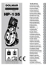
DOLMAR HP-135
Brand: Makita Pages: 113
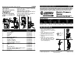
PW1380
Brand: Campbell Hausfeld Pages: 13
PW1750
Brand: Campbell Hausfeld Pages: 18
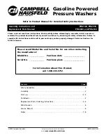
PW2120
Brand: Campbell Hausfeld Pages: 8
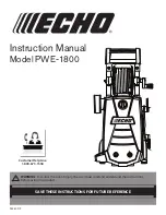
PWE-1800
Brand: Echo Pages: 20
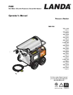
PHW
Brand: Landa Pages: 26
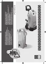
POWER
Brand: Lavor Pages: 20
HD 10/25 S VEX
Brand: Kärcher Pages: 44
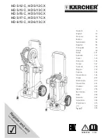
HD 5/12 C
Brand: Kärcher Pages: 20
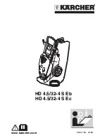
HD 4.5/32-4 S Eb HD 4.5/32-4 S Ec
Brand: Kärcher Pages: 36
HD 5/12 C
Brand: Kärcher Pages: 65
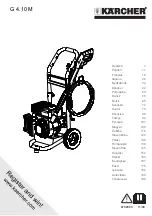
G 4.10 M
Brand: Kärcher Pages: 208
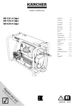
HD 7/11-4 Cage
Brand: Kärcher Pages: 196


