background image

HUSQVARNA CONSTRUCTION PRODUCTS

Workshop manual

WS440

HF

, WS482HF

PP440

HF

, PP480HF

PP490HF

Summary of Contents for PP440HF

Page 1: ...HUSQVARNA CONSTRUCTION PRODUCTS Workshop manual WS440HF WS482HF PP440HF PP480HF PP490HF ...

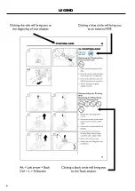
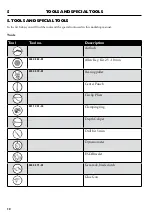
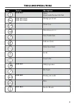
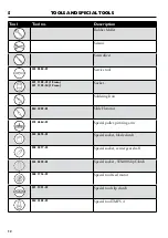
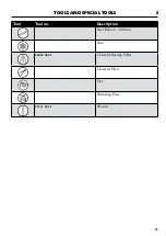
Page 2: ...2 LEGEND ...

Page 3: ...ance The service related differences between the WS480 and WS440 17 The service related differences between the PP480 and PP440 18 The service related differences between the PP480 and PP490 19 Funktion Test WS400 HF 20 Function Test Power Pack 21 Function test Remote Control 22 WS400 HF Service 25 Power Pack Service 27 RC Unit Sevice 27 Service 100h 28 Service 200h 29 8 Technical Information andT...

Page 4: ...e is parallel with the Blade 73 Remove Blade Flange 74 Renovate Blade Flange 74 10 2 Saw Arm Detach Arm Housing 77 Inspect the Clutch 78 Disassemble Arm 79 Remove Clutch Gear Shafts 80 Inspect Clutch Gear Shafts 82 Align Clutch Gear Shafts Only WS482 83 Disassemble the Gear Selector Only WS482 84 Install the Gear Selector Only WS482 85 Reinstall Clutch Shafts 86 Click for 3D steps 86 Replace Beari...

Page 5: ...smantle the Motor 106 Replace Motor Bearings 107 Replace the Motor Temp Sensor 109 Assemble the Motor 110 Remove Feed Shaft 111 Measure the Teeth Wear 112 Inspect the Track Feed Slip Clutch 112 Disassemble the Track Feed Slip Clutch 113 Replace the Needle Bearing 114 Assemble the Track Feed Slip Clutch 115 Replace the Arm Feed Bearing 116 Assemble the Feed Shaft 118 Click for 3D steps 118 Assemble...

Page 6: ...e DIN rail bracket 138 Replacing the Main Board 139 Replacing Controller Board 141 Water Valve 142 Dismantle the Inverter Board 143 Assemble the Inverter Board 145 12 Firmware Upgrade What is what on the Multiprogrammer 146 Firmware update for PP440 PP480 and PP490 146 Inverter side 147 Main Board side 149 Firmware update for PP440 Controller board only 153 Upgrade the RC unit firmware 155 Functio...

Page 7: ...husqvarnacp com We recommend that Husqvarna ser vice centres log on to the support site and find spare parts in the Electronic Parts Catalogue EPC Operator s Manual The operator s manual describes how the machine is to be used the functions of the machine and the maintenance the operator normally carries out This manual also contains important instructions for the safe handling of the machine It i...

Page 8: ...regulations Electric shock could cause injury Do not touch wires while the WS400HF and PP400HF is on Always make sure all nuts and bolts are correctly tightened Wear personal protective equipment See instructions under the heading Personal protective equipment Never carry the machine by holding the cable and never pull the plug by pulling the cable Check that the cables are intact and in good cond...

Page 9: ...d to store the equipment Start Blade Rotation The return button must be pushed and held to be able to start the blade rotation This is in order to prevent unintended starting of the blade rotation Emergency Stop Button The powerpack is equipped with an emergency stop and the remote control with a stop botton These are used to be able to quickly shut down the power pack Note that voltage will still...

Page 10: ...he special tools used in this workshop manual Tools Tool Tool no Description Airfluch 525 45 52 01 Allen Key Kit 2 5 10 mm 523 05 79 01 Bearing puller Center Punch Circlip Pliers 531 12 31 22 Clamping ring Depth Caliper Drill bit 5 mm Dynamometer ESD Bracelet 523 05 71 01 Gear rack blade clutch Glue Gun ...

Page 11: ... Peerless OG2 Red 522 93 44 01 6 pin 522 93 43 01 3 pin Harting special tool Heater Gun Heat silicone 150 C Heat Transfer Paste Indicator Clock Knife Razor blade Loctite Long Socket 501 49 35 01 Multiprogrammer Pin Punch 522 90 84 01 Pivoting arm cradle Pliers 531 11 95 32 Ratchet Wrench ...

Page 12: ...95 34 19 mm Socket Soldering Iron 584 39 99 01 Slide Hammer 575 46 64 01 Special puller pivoting arm 523 05 76 01 Special socket blade clutch 505 38 17 23 Special socket center gear shaft 523 05 78 01 Special socket WS400 Slip Clutch 588 17 16 01 Special tool feed motor 531 12 31 23 Special tool slip clutch 584 23 05 01 Special tool TMFS 4 ...

Page 13: ...5 13 TOOLS AND SPECIAL TOOLS Tool Tool no Description Steel Ruler 0 300 mm Torx 504 90 90 02 Universal Bearing Puller Universal Pliers Vice Workshop Press 531 11 95 33 Wrench ...

Page 14: ...or for blade 3 Blade guard guide 4 Blade guard guide lever lock 5 Spindel hub 6 Handle Blade Guard Mount 7 Harting connector to PP 8 Cooling water out to blade 9 Cooling water in from PP 10 Wall saw carriage lever lock 11 Wall saw carriage 12 Serial number badge 13 Track 14 Wall mount 15 Saw head 16 Blade flange WS 482 HF ...

Page 15: ...E Connector DM PC 7 Harting connector for saw head 8 Water connector out to saw head 9 Power lead orange main cable 10 Water hose 11 Handle 12 Ground fault circuit breaker Residual Current Device RCD 13 Power inlet connector 14 Water connector in to power pack 15 Power Pack 16 CAN bus cable 17 Blade rotation and start water coolant 18 ON OFF button 19 Stop botton function 20 Remote control 21 Dept...

Page 16: ... VDR 510V 3 Cooling plate 4 Fuse 1A 5 Main contactor 6 Main board 7 24V Transformer 8 Blade brake resistor 9 WS contactor 10 PRIME contactor DM PC 11 Fuse 15A 3x 12 Main board Seen from the other side 13 Water valve 14 CAN bus connector 15 Controller board 16 Inverter board ...

Page 17: ...n the WS480 and WS440 WS 480 1 2 micanical gears In the arm 2 Gear selector 3 Larger motor with an extra water connection 4 The motor is slightly longer with a different bumper bar 5 Water cooled arm Between saw head and arm 6 Different motor interface card WS 480 WS 440 7 SERVICE AND MAINTENANCE ...

Page 18: ...ICE AND MAINTENANCE The service related differences between the PP480 and PP440 WS 480 1 Seperate EMC filter board Intergrated in the inverter inside PP440 2 Longer chassis 3 Diffrent Inverter board 4 Diffrent Controller board PP 480 PP 440 ...

Page 19: ...se 1A 4 WS contactor 5 PRIME contactor DM PC 6 Fuse 15A 7 Reset button 230V Only 5 pin machines 8 PRIME connector DM PC 9 Diffrent Ground fault circuit breaker and moved to the other side 10 Removed Main switch 11 Different Transformer PP480 400VAC 24VDC PP490 750VDC 24VDC The service related differences between the PP480 and PP490 ...

Page 20: ...or is running but we can t achieve 290 kg 640 lb the clutch is slipping Re adjust or replace clutch Carefully take up the slack in the belts and then turn up the control to full speed to achieve max force Cleaning 1 These function tests help to reveal the current condition of the feeding motor slip clutches and gears The results of these tests will help you to determine what course of action to ta...

Page 21: ...re the play It should be less than 1 5 mm at the blade flange hub Large slack might indicate a worn damaged gearwheel or a problem with the gearbox 1 3 2 Function Test Power Pack 1 Check the emergency stop function 2 Check the remote control stop button function 3 Check the power indicator function 4 Check the single phase output 230 V function 5 pin machines only 5 Check the ground fault circuit ...

Page 22: ...access code in this case is 08100 Use the up or down arrows to set this number and then OK to go to the next position Confirm by pushing OK 5 Once in the Service menu use the up or down arrows to navigate to Product Status Push OK 6 Use the up or down arrows to get to the Potentiometers menu Push OK 7 In this menu the values in percent can be checked for each potentiometer For feed motor potentiom...

Page 23: ...usted 1 Loosen the two hexagon socket screws with an Allen key Also loosen the two stop screws which locks the two exentiric guide wheels with an Allen key 2 Turn the shafts gently with an Allen key until the guide wheels rest agains the rail 3 Hold the guide wheels in position and tighten the two stop screws 4 Press down the locking device and pull the saw carriage in both directions by hand Carr...

Page 24: ...ith a 3 mm allen key 2 Turn the two excenter sleeves with a 8 mm allen key until the shaft is tight and parallell to the saw unit 3 Tighten the two stop screws with a 3 mm allen key 4 Remove the saw head from the carriage Doublecheck that the two Allen lock screws are tightened when the saw head is off 5 Make sure the locking handle is properly adjusted by open and close and see that the spring lo...

Page 25: ...ts and wear on electric cables X X X Check continuity of the earth wiring through out the machine X X X Condition of the remote control X X X Conduct a functional test X X Funktion Test WS400 HF p 20 Replace the blade bolt on the blade flange X X Service 200h p 29 Replace the guide blocks on the blade guard X X Service 200h p 29 Replace the bearings on the blade guard guide wheels X X Service 200h...

Page 26: ...silicon seals X Service 200h p 29 Replace the pins connectors and ground frame in the haring connector to the saw head X Dismantling the Saw Head Electronics p 99 Replace all the o rings seals and gasket on the pivoting arm X Mount Saw Arm p 95 Replace bearings in the pivoting arm and check the slip tourque on the seperate shafts X Inspect Clutch Gear Shafts p 82 Replace the weare and tear parts i...

Page 27: ...X X Listen for abnormal noises X X X Conduct a functional test X X Change the screen protection on the remote control X X Inspect the aeration diaphragm and change it if damaged or worn on both PP and saw head X X Service 100h p 28 Open the box sides and check inside for coolant leakage concrete dust etc X X Opening the PP 490 p 124 Clean the filter on the incoming cooling water connection X X Wat...

Page 28: ...heel and rollers on the saw carriage 5 Housing Lubricate the worm gears with a grease pump until you see new grease comming out 6 RC Unit Change the screen protection on the remote control 7 Aeration Diaphragm and Motor Inspect the aeration diaphragm and change it is damaged or worn on both PP and saw head Remove Motor p 105 8 Oil Change Remove the oil plug with an allen key and drain the arm of o...

Page 29: ...heel and rollers on the saw carriage 5 Housing Lubricate the worm gears with a grease pump until you see new grease comming out 6 RC Unit Change the screen protection on the remote control 7 Aeration Diaphragm and Motor Inspect the aeration diaphragm and change it is damaged or worn on both PP and saw head Remove Motor p 105 8 Oil Change Remove the oil plug with an allen key and drain the arm of o...

Page 30: ...or Replace the o rings and seals on the feed motors Remove Feed Motors p 101 11 Electrics Replace all the seals for the saw head electronics don t miss the blue silicon seals Assemble Feed Motors p 120 Cable Replace the pins connectors and ground frame in the haring connector to the saw head Dismantling the Saw Head Electronics p 99 and Assemble the Saw Head Electronics p 121 ...

Page 31: ...lways use the new orange remote control when fault tracing Also make sure the firmware in both remote control and PP are the latest ones Note If possible try to replace PP saw head and orange main cable one at the time to determine which part to trouble shoot The layout of the guides are as if there were no extra PP saw head or orange cable 8 TECHNICAL INFORMATION AND TROUBLESHOOTING General Temp ...

Page 32: ...ool Other reasons may be that the temperature sensor in the HF motor is poorly connected or is defective The fault may however not be due to an insufficient oil level in the motor Check the troubleshooting manual for the respective tools F0112 Low input voltage detected This error is due to the input voltage being too low It can also be caused by using extensions cords that are too long or thin or...

Page 33: ...nd then Main Board one at the time F0119 Temperature in the PP too high Water coolant is lacking insufficient to powerpack Check that the water coolant flows to the power pack and that it is max 25 C and min 3 5 l min If the message pops up when the blade rotation is started go to the operations menu and Water coolant and select ON Let the water coolant circulate the power pack for a minute before...

Page 34: ...es for acknowledging fault messages Activate the trigger on the connected tool No further action is required if the flashing stops If the fault persists follow the instructions given in the troubleshooting guide or get in touch with an authorized dealer The power unit software can be updated Contact your service agent for further information 1 Red 2 Yellow 3 Green 4 Green 5 Green ...

Page 35: ... 44 F15 No DSP Response 45 Power Supply 46 Power Inlet Connector in PP 47 RCD 48 Contactor and Emergency Stop 49 PULS Transformer and Main Board 50 Ground or Neutral Fault Inlet Side 51 Ground Fault Outlet Side 52 Water Connection 52 Feed Motors 53 Blade Motor Electrics 54 Blade motor Mechanics 54 Harting connector and orange main cable checkup 55 No life sign from equipment 56 Can t move the arm ...

Page 36: ...ge No Tool 61 Communications 61 Internal Water Valve 62 Fuses in the wall keep tripping 63 External Ground Fault Circuit Breaker trips when turning on or off the equipment 64 PP Blade Motor Circuit 64 PP Feed Motor Circuit 65 WS contactor and DM PC contactor 66 ...

Page 37: ...8 37 TECHNICAL INFORMATION AND TROUBLESHOOTING Trouble Shooting Tree Water Connection p 52 Replace the Motor Temp Sensor p 109 Temp Sensor p 109 Replace the Motor ...

Page 38: ...38 8 TECHNICAL INFORMATION AND TROUBLESHOOTING Water Connection p 52 Dismantle the Inverter Board p 142 Power Supply p 46 Dismantle the Inverter Board p 142 ...

Page 39: ... AND TROUBLESHOOTING Harting connector and orange main cable checkup p 55 Blade Motor Mecanics p 54 PP Blade Motor Circuit p 64 Arm p 79 Disassemble Blade Motor Blade Motor Mecanics p 54 Mecanics p 54 Blade Motor Electrics p 54 ...

Page 40: ...40 8 TECHNICAL INFORMATION AND TROUBLESHOOTING Harting connector and orange main cable checkup p 55 Simplified Wiring Diagram p 159 Simplified Wiring Diagram p 159 Function test Remote Control p 22 ...

Page 41: ...ICAL INFORMATION AND TROUBLESHOOTING PP Feed Motor Circuit p 65 Harting connector and orange main cable checkup p 55 Inspect Clutch Gear Shafts p 82 F05 p 39 Inspect the Clutch p 78 Feed Motors p 52 WS Setup p 60 ...

Page 42: ... checkup p 55 Harting connector and orange main cable WS contactor and DM PC contactor p 65 Generator and Transformer Setup p 58 Assemble the saw F05 p 39 Head Electronics p 121 Ground or Neutral Fault Inlet Side p 51 Ground Fault Outlet Side p 52 ...

Page 43: ...8 43 TECHNICAL INFORMATION AND TROUBLESHOOTING Function test Remote Control p 22 ...

Page 44: ...44 8 TECHNICAL INFORMATION AND TROUBLESHOOTING Power Supply p 46 ...

Page 45: ...8 45 TECHNICAL INFORMATION AND TROUBLESHOOTING Board p 142 PP 490 Internal p 16 Dismantle the Inverter Replacing the Main Board p 138 ...

Page 46: ...46 8 TECHNICAL INFORMATION AND TROUBLESHOOTING Harting connector and orange main cable checkup p 55 Contactor and Emergency Stop p 49 Power Inlet Connector in PP p 47 Inlet Connector in PP p 47 Power ...

Page 47: ...8 47 TECHNICAL INFORMATION AND TROUBLESHOOTING current device RCD p 127 Contactor Replacing the Power Inlet and the Residual and Emergency stop p 49 RCD p 48 ...

Page 48: ...AND TROUBLESHOOTING Power Inlet Connector in PP p 47 Contactor and Emergency stop p 49 Ground or Neutral Fault Inlet Side p 51 Replacing the Power inlet and the Residual current device RCD p 127 Emergency stop p 49 Contactor and ...

Page 49: ...8 49 TECHNICAL INFORMATION AND TROUBLESHOOTING Power inlet connector in PP p 47 RCD p 48 Power Supply p 46 ...

Page 50: ...50 8 TECHNICAL INFORMATION AND TROUBLESHOOTING Power Supply p 46 Power inlet connector in PP p 47 RCD p 48 Contactor and Emergency stop p 49 ...

Page 51: ...8 51 TECHNICAL INFORMATION AND TROUBLESHOOTING Power Supply p 46 Power inlet connector in PP p 47 Ground Fault Outlet Ground Fault Outlet side p 52 Side p 52 Power inlet connector in PP p 47 ...

Page 52: ...52 8 TECHNICAL INFORMATION AND TROUBLESHOOTING Internal water valve p 62 ...

Page 53: ...8 53 TECHNICAL INFORMATION AND TROUBLESHOOTING Harting connector and orange main cable checkup p 55 WS Setup p 60 F06 F07 Hall Sensor p 40 Remove Motor p 105 Remove Feed Motor Gearbox p 102 ...

Page 54: ...54 8 TECHNICAL INFORMATION AND TROUBLESHOOTING Assemble the Saw Head Electronics P 121 Dismantle the Motor p 106 ...

Page 55: ...8 55 TECHNICAL INFORMATION AND TROUBLESHOOTING ...

Page 56: ...56 8 TECHNICAL INFORMATION AND TROUBLESHOOTING ...

Page 57: ...7 TECHNICAL INFORMATION AND TROUBLESHOOTING Function test Remote Control p 22 Harting connector and orange main cable checkup p 55 Circuit p 64 PP Blade Motor F10 Blade Jam p 41 Blade Motor Electrics p 54 ...

Page 58: ...58 8 TECHNICAL INFORMATION AND TROUBLESHOOTING ...

Page 59: ...OUBLESHOOTING Harting connector and orange main cable checkup p 55 Remote Contol potentiometer failure p 57 Feed Motors p 53 Harting connector and orange main cable checkup p 55 Remote Contol potentiometer failure p 57 Feed Motors p 53 ...

Page 60: ...60 8 TECHNICAL INFORMATION AND TROUBLESHOOTING ...

Page 61: ...o Tool Remove the Motor Interface board from the saw head Connect the red wire from the MIB directly to the PP Harting outlet socket T4 black to T5 blue A4 and white to A5 When everything is turned on does the remote control display show the saw head model WS440 or WS482 Does it work with another Motor Interface Board The MIB works Check all connections again Action Replace the Motor Interface Boa...

Page 62: ...62 8 TECHNICAL INFORMATION AND TROUBLESHOOTING Dismantle the Inverter Board p 142 Function test Remote Control p 22 PP 490 Internal p 16 ...

Page 63: ...8 63 TECHNICAL INFORMATION AND TROUBLESHOOTING Harting connector and orange main cable checkup p 55 Connector in PP p 47 Power inlet RCD p 48 Blade Motor Electrics p 54 Ground Fault Outlet Side p 52 ...

Page 64: ...64 8 TECHNICAL INFORMATION AND TROUBLESHOOTING Harting connector and orange main cable checkup p 55 Fuses in the wall keep tripping p 63 ...

Page 65: ...8 65 TECHNICAL INFORMATION AND TROUBLESHOOTING ...

Page 66: ...66 8 TECHNICAL INFORMATION AND TROUBLESHOOTING ...

Page 67: ...arm feed It s normal for this LED to be flashing or being dimly lit during wall saw operation If lit the arm feed is disabled Probable cause is short circuit between at least two arm feed motor phases MA1 Lit when the processor for arm control has established contact with main processor ML2 Over current track feed It s normal for this LED to be flashing or being dimly lit during wall saw operation...

Page 68: ...ue circuit with XBee written on it Lights up when a remote has been paired to the PP Will go out when switching radio channels Will come on again if paired with a remote D326 Situated right next to D325 under the radio module Flashes two times a second 2 Hz as soon as radio is associated Should always be flashing ...

Page 69: ...rner motor interface 3V3 Indicates that controller board has power PWREN Lit when power is delivered to blade motor FAULT Lights up for a short while if short circuit or other peak current is detected on blade motor output BRAKE Lit when power is directed to breaking resistor i e when electric blade brake is active DLED1 19 kW motor setup DLED2 13 kW motor setup DLED3 Not in use DLED4 Not in use ...

Page 70: ...BSF_PHASE At least one phase missing software BLED1 BLED3 BSF_OVERVOLT Over voltage internally in boost transformer BLED2 BLED3 BSF_OVERCURR Over current software BLED1 BLED2 BSF_OVERLOAD Overload blade motor is taking too much BLED3 current BLED4 BSF_OVERINPUT Over voltage on incoming BLED1 BLED4 BSF_AUTOCAL Unsuccessful automatic calibration BLED2 BLED4 BSF_TIMING Internal timer error Software o...

Page 71: ...ter clockwise and 100 when it is turned fully clockwise When the feed motor potentiometers are pointing straight up the readings should be 50 If the readings differ from 50 and 100 go to calibrate If 0 can t be achieved even by mechanically repositioning the potentiometer then the potentiometer has to be replaced 3 Put the potentiometer in the position you want it to show 50 i e straight up and pu...

Page 72: ...sembly 1 Press the new bearing into place 2 Put the circlip back into position using a circlip pliers 3 For the adjustable wheels put the spacer nut and wheel into position and tighten the hex screw on the back Use a wrench on the front 4 For non adjustable wheels put the spacer nut and wheel into position and tighten the screw with a wrench Check that the wheels spin easily by hand Remember to ca...

Page 73: ... play on the blade guard 3 Tighten the hex screw on the back while using the wrench as a counter force Checking that the Blade Guard Guide is parallel with the Blade 1 Mount the Blade Guard Guide on the guide and measure between each of the end wheels and the blade The measurement between the outside of the wheel guide and the blade shall be approximately 92 2 mm 2 If the difference is larger than...

Page 74: ... to remove the blade flange 4 Remove the blade shaft 1 Unscrew the spindle hub to remove the outer flange 2 Remove the 4 screws and the washer 3 Turn the blade flange over and remove the 6 Allen screws and the stop washer 4 Remove the inner flange from the hub by a gently hit with a rubber mallet to the center 2 2 First see Remove Blade Flange p 74 ...

Page 75: ...nnection hose 7 Remove the water block from the hub 8 Remove the 2 seals from the hub with a flat screwdriver 9 Use a workshop press to remove the bearing Use a collar underneath to get clearance for the bearing 10 Use a workshop press to insert the new bearing to the hub Pressurize on the outer ring of the bearing 10 ...

Page 76: ...ter connection hose with the 2 Allen screws 16 Use a workshop press to fit the hub to the inner flange Use a collar to pressurize the inner ring of the bearing Suggested the old bearing 17 Replace the O ring on the hub Grease the new O ring when assemble 18 Assemble the stop washer with 6 new Allen screws Tighten the bolts crosswise to make sure that the inner flange is completely inserted in the ...

Page 77: ...77 REPAIR INSTRUCTIONS 1 2 3 4 Detach Arm Housing 1 Loosen the 6 screws that holds the arm 2 Be careful when you loosen the top screw as the arm can fall 3 Remove the screws 4 Lift the arm away 10 2 SAW ARM ...

Page 78: ...e at what torque the arm is slipping For a WS482 in 2 nd gear the toque value should be 70 85Nm recorded while the clutch is slipping For a WS482 in 1 st gear the value is about 10 Nm lower Test in both directions 6 To check the slip clutch for a WS440 attach the special tool 523 05 78 01 to the torque wrench A WS440 should slip at 70 85Nm Test in both directions First see Detach Arm Housing p 77 ...

Page 79: ... Remove the three screws holding the lid 3 Apply heat to the lid to prevent the bearings inside from sticking to the lid 4 Place the tool 575 46 60 01 on top of the lid 5 Insert the screws into the threaded holes 6 Turn down the center screw and pull the lid up First see Inspect the Clutch p 78 ...

Page 80: ... 3 3 Pull the center bearing nr 2 off with a universal bearing puller 4 Remove the two clutch gear shafts nr 1 assembled with the bearing with special Tool nr 584 39 99 01 First see Disassemble Arm p 79 WS 440 does not have the two Idler gear shafts Nr 1 in orientation picture because it doesn t have a gear selector Orientation Picture of the shafts 1 Clutch gear chafts 2 Center gear shaft 3 Idler...

Page 81: ...39 99 01 6 Remove the center gear 7 Remove the two idler gear shaft nr 3 using special Tool nr 584 39 99 01 8 Use outer bearing puller to make a gap between the bearing and the clutch gear shaft nr 1 9 Use a bearing puller to remove the bearing from the clutch gear shaft nr 1 10 Remove the gear shift arm 10 WS482 ...

Page 82: ... Place the special tool 523 05 76 01 in a vise and position the clutch shaft inside the tool 5 Use a pin punch to bend the pegs down 6 Place the special tool TMFS 4 523 05 77 01 on top of the clutch gear shaft to unscrew the slotted lock nut First see Remove Clutch Gear Shafts p 80 At least 55Nm in motion If the assembled arm slips at the correct torque in Inspect the Clutch on page 78 Step 5 abov...

Page 83: ...ith the timing mark on the other side align with the flat tip of the other gear wheel First see Remove Clutch Gear Shafts p 80 WS482 7 8 9 At least 55Nm in motion 7 Disassemble the slip clutch into the pieces shown in the figure Inspect all parts and replace both clutches if worn Internal parts are not available Replace whole shafts 8 When assembling ensure that the gear is mounted with the two ma...

Page 84: ...ng nut 3 Attention Be careful and protect your eyes Use a glove or cloth and cover the hole Turn back the gear selector until the ball and spring intend to jump out 4 Carefully remove the ball and spring 5 Clean the gear selector thoroughly internally with strong anti grease to be able to get the balls and second spring out 6 Turn the gear selector 90 and tap the arm against a table to get the nex...

Page 85: ... ball in the hole 5 Press the ball down with a pin punch and turn back the gear selector to make the ball fall into place 6 Now carefully turn the gear selector back 7 Turn the gear selector horizontally and place the ball in the hole 8 Insert the locking screw 9 Turn the gear selector 180 unscrew the locking screw and place the remaining ball in the hole 10 Insert the locking screw First see Disa...

Page 86: ...it down with a rubber mallet 4 Insert the first idler gear shaft 5 Insert the second idler gear shaft 6 Insert the first clutch gear shaft First see Remove Clutch Gear Shafts p 80 Reinstall Clutch Shafts WS482 WS482 WS482 WS482 2 WS482 WS482 WS 440 does not have the two Idler gear shafts Nr 1 in orientation picture because it doesn t have a gear selector Orientation Picture of the shafts 1 Clutch ...

Page 87: ...also have a specific position adjacent to the gear wheel 8 Insert the second clutch gear shaft 9 Make sure the timing marks on the clutch shaft align with the timing marks on the gear shaft 10 Make sure that each shaft is aligned along an imaginary line 11 Make sure that you can shift to first gear while turning any shaft back and forth 12 Insert the bearings on the shafts WS482 WS482 WS482 7 WS48...

Page 88: ...eth have an equal timing and thereby even wear on the cogs Preferably use a dial torque wrench to measure the slip torque at the same time A click type torque wrench will measure the top valve for the slip and not the torque in motion 18 Grease the three pins and insert them in the grooves Then place a 16mm socket over the shaft and pins Use a torque wrench to measure the arm slip torque For a WS4...

Page 89: ...et clearance for the shaft and bearing Use a heat gun and apply heat to bearing and shaft 5 Apply a spacer and the special tool 575 46 60 01 on top of the shaft 6 Attach special tool with its six screws and tighten the center screw 7 Continue tightening the center screw until the shaft and bearings is pressed out 8 Unscrew the six screws holding the ring 9 Press or tap the ring out 10 Remove the o...

Page 90: ... 13 Place the arm on blocks and tap the screw with a mallet 14 Tap the screw until it goes all the way inside 15 Remove the screw 16 Use a pin punch in the two holes to rotate the shaft 17 Rotate the shaft until you see surfaces to press on 18 Use a pin punch and knock the axle out 19 Slide the spacer and the gear wheel with bearing to the side and lift it out 20 Remove retaining ring and bearing ...

Page 91: ...e the old O ring inside it 6 Apply heat to the inner ring of the bearing with a heater gun to easier press the axis out 7 Use a spacer smaller than the inner radius of the bearing and special tool 575 46 60 01 8 Tighten the top screw and press the axle wheel out 9 Press the axle bearing out with a workshop press 10 Heat the contact surface to easily fit the new bearing Replace Axle Bearing 1 7 3 5...

Page 92: ...op press to insert the new bearing to the hub Pressurize on the outer ring of the bearing 12 Fit and grease a new o ring to the hub 13 Use a workshop press to insert the axle wheel to the Bearing Put pressure on the inner ring of the bearing 11 13 ...

Page 93: ... recessed hole Grease and fit new o rings and assemble the axis with a workshop press 4 Flip the pivoting arm over to the other side and fasten the axis with the lock screw 5 Fit a new bearing to the lid by pressurise the outer ring of the bearing with a workshop press 6 Grease and fit a new o ring and assemble the ring 7 Use a workshop press to fit the axle wheel to the arm Use one collar that pr...

Page 94: ...plate 10 Use some grease and insert the shaft seal into the cover plate 11 Grease the O ring and assemble it with the gland to the axis 12 Assemble the lid by tighten the six screws crosswise 13 Turn over the pivoting arm Grease and assemble the shaft seal with the o ring the radial seal and the o ring 14 Assemble the ring with the six screws ...

Page 95: ...Loosen the two locking screws on top of the connector 7 Rotate the screws until the excenters are in their lowest position and the flat screw heads are vertical 8 Tighten the locking screws 9 Apply grease to the outer surface and insert a brand new X ring 10 Apply grease to the surface and then insert a brand new X ring Mount Saw Arm 1 2 4 6 8 7 10 9 5 3 First see Detach Arm Housing p 77 WS482 WS4...

Page 96: ...14 Insert the bolt located at six a clock 15 Insert the bolt located at twelve a clock Make sure the X ring is in place and doesn t get damaged 16 Insert the remaining four bolts without tighten them 17 Turn the arm and loosen the two locking screws on the cooler 18 Turn the excenters until they barely touch the Handle Blade Guard Mount 19 Make sure the excenter is in contact with the frame 20 Tig...

Page 97: ...h the two screws 24 Turn the arm to its upright position Tighten the bolts crosswise in 3 steps Tighten all bots at first to 5Nm At second step tighten all the bolts to 10 Nm At the third and final step tighten all bolts to 17Nm 25 Connect the 2 hinges by gently bending them in place 26 Close the cover by flipping the 2 hinges 21 WS482 24 ...

Page 98: ...4 Lift the orange cover off 5 Disconnect the hoses by pulling the water nipples back and pull the hose out 6 Remove the water cooling attachment WS482 WS482 10 3 SAW HEAD Remove Handle Blade Guard Mount First see Remove Covers p 98 1 3 2 1 Remove the four screws holding the handle to the motor 2 Remove the two screws holding the handle to the housing 3 Lift the handle away First see Detach Arm Hou...

Page 99: ...ocket You may need to loosen the ground wire from the frame with a screwdriver as in Pic 5 4 Fold the two halves of the frame outwards and press the harting connectors down 5 Unscrew the ground cable and remove the frame 6 Unscrew the 3 screws inside the plug using an Allen key 7 Use special tool 522 93 44 01 to remove the cables Insert it next to the cable press gently and pull the cable out 8 Re...

Page 100: ...d the wires out 10 Remove the four screws holding the bracket 11 Gently thread out the wires and lift the bracket off Inspect the silicone seals and replace them if they are damaged 12 Loosen the two screws holding the circuit board 13 Lift the circuit board away ...

Page 101: ... Remove the four screws on the feed motor 4 Lift the feed motor away 5 Remove the four screws on the feed motor 6 Lift the feed motor away 7 Make sure to remove the shrink tubing and wire seal to be used on the new feed motor 8 When assembling the electric motor use special tool 505 53 86 01 9 Center the electric motor with special tool 505 53 86 01 and tighten all 4 screws Reverse steps for reass...

Page 102: ...isc to force the arm gearbox out 3 Use a screwdriver to rotate the track wheel to force the track gearbox out 4 When the gearbox got enough clearance from the house unscrew the gearbox by hand the last bit and lift the gearbox out 5 Unscrew the bottom bolt and remove the worm screw with the radial bearing from the planatary gearbox 6 Remove the four screws holding the lid 7 Remove the lid 5 1 2 3 ...

Page 103: ...lay on Feed Motor Gearbox First see Remove Feed Motor Gearbox p 102 1 Fasten the gearbox with the four bolts 2 Turn the engine over and place the washers and bearings on the bottom of the gearbox 3 Measure distance A and distance B using a calliper The difference between A and B should be between 0 and 0 05 mm The distance can be adjusted by adding or removing shims ...

Page 104: ...ace and grease the o ring 3 Lubricate the worm screw and reinsert the gearbox 4 Fasten the gearbox with the four screws 5 Lubricate and insert a new needle bearing to the worm screw 6 Lubricate and replace the o ring 7 Place the washers and bearings on the bottom of the gearbox 8 Lubricate and replace the o ring on the lid 9 Reinsert the lid at the bottom and fasten it with the 4 screws 2 3 1 4 5 ...

Page 105: ...e Perform steps 1 9 in chepter Dismantling the Saw Head Electronics p 99 before starting here 1 Remove the two screws on top of the motor using a short Allen Key 2 Remove the two screws located under the motor 3 Lift the motor away Reverse steps for reassembly ...

Page 106: ...head weakens the thread locking 3 Remove the 4 screws 4 4 Lift off the motor bracket 5 Loosen the cable seal Grip it with an opened wrench and unscrew the nut 6 Remove the 9 screws holding the bearing shield Lift the motor cover while the cables are pressed in order not to expose them to major tensile forces 7 Lift off the two wave washers 1 3 4 2 5 7 6 ...

Page 107: ... the rotor Note Dismantled rotor Keep the rotor away from metal objects that would otherwise attach with force Note that the ball bearings outer rings have O rings 2 Remove the 2 bearings using bearing puller 531 00 48 67 Note The ball bearings outer rings have O rings 3 Fit the new bearings by pressing them into place with a socket that supports the inner ring of the bearings First see Dismantle ...

Page 108: ... 5 Note The rotors magnetic force has an element of risk during assembly The rotor will be drawn in with great force and speed Wear heavy duty protective gloves Move the rotor slowly into the stator with a light grip on the shaft Let the rotor pull out of the grip The weight and speed of the rotor means the inner bearing is virtually self assembling as a result of the force ...

Page 109: ...es along the way to where the cables exit the motor 3 Cut and peal the blue and brown wires as close to the coil as possible without harming the coil or the other wires Slide on a couple of centimetres of heat shrink tube on each one of the wires before soldering them together Solder one white wire to the blue one and the other white to the brown which one doesn t matter Slide the heat shrink over...

Page 110: ...O ring 3 Lubricate and fit the two wave washers 4 Apply Loctite 577 or Loctite 5400 to the screws threads Push down the cover and fit the screws Tighten the screws alternately all around 5 Retighten the cable seal 6 Reassemble the motor bracket Apply Loctite 577 or Loctite 5400 to the screws 7 Lubricate and replace the O ring 1 3 4 2 5 7 6 First see Dismantle the Motor p 106 ...

Page 111: ...5 1 Remove the lock ring 2 Prop up the housing Put a socket on top of the shaft and put it in a workshop press 3 Use a heater gun and apply heat to the bearing housing 4 Press the shaft out 5 Tap the housing against a table to get the track feed slip clutch out 6 Press the top bearing out ...

Page 112: ...t it in a vice 3 Add special tool nr 531 12 31 22 on top of the slip clutch and tighten the bolt 4 Use a torque wrench to determine the slip torque The torque in motion should be 125 140 Nm 104 109 lbf ft The teeth wear of the brass wheel is measured over six teeth The measurement must be made in the middle of the gear wheel A new gear wheel has the dimension 25 3 mm over six teeth If the value is...

Page 113: ...nscrew it by hand and lift it off 6 Lift the washer the 3 spring washers and gearwheel off 7 Remove the old o ring 8 Inspect the friction lining If it is coated with lubricant or oil it must be replaced The friction lining is glued to the worm wheel Insert a knife under the coating and break it up Clean the surface of all glue remnants Note A new friction washer needs to be under pressure for 5h b...

Page 114: ...und 100 C 200 F 2 Place the worm wheel in a workshop press 3 Use a tool socket and press out both needle bearings 4 Mount the worm wheel s needle bearings using a workshop press Press in the first bearing in line with the bearing housing 5 Press in the bearing on the opposite side The tool 523 05 76 01 fits ideally for pressing in the bearing in line with the worm wheel ...

Page 115: ...to be assembled 2 Fit the 2 new o rings 3 Fit the gearwheel Important that is no grease between the friction washer and gearwheel 4 Lubricate and fit the 3 spring washers Note how these are to be turned The inner diameter must be the highest point on all washers Then lubricate and fit the flat washer to the gear wheel 5 Fit and tighten the pressure plate to a torque of 85 95 Nm 63 70 lbf ft using ...

Page 116: ...ve the plastic plugs using a screwdriver 4 Turn the shaft and place a support under this 5 Heat the worm wheel to about 100 C 200 F 6 Knock out the ball bearing and gear wheel with a pin punch through the holes in the shaft Apply some light taps alternately between the two holes 7 Mount the ball bearing with a workshop press Use a collar that pressurizes the inner ring of the bearing 7 ...

Page 117: ...aring Ensure that no lubricant ends up on the shaft 10 Apply Loctite 648 or Loctite 6300 to the wedge seats 11 Knock down the wedges using a pin punch 12 Apply Loctite 648 or Loctite 6300 to the shaft where the worm wheel is to be fitted 13 Align the worm wheel with the wedges and press in the worm wheel fully down on to the ball bearing using a workshop press ...

Page 118: ... 3 Mount the arm carrier ring 4 Place the set of 2 washers and bearing on the shaft 5 Place the slip clutch and another set of washers and bearing on the shaft 6 Apply grease to a new o ring and thread it on the shaft 7 Lubricate properly all over the gear wheels the bearing and o rings 8 Apply heat to the housing 9 Insert the complete shaft into the housing Attention The housing is hot Click for ...

Page 119: ...10 3 1 1 9 REPAIR INSTRUCTIONS 11 10 10 Insert and press the bearing in place 11 Fit the circlip ...

Page 120: ...and silicone wire seals from each feed motor into the feed motor cover 5 The feed motor cover has oval holes Check the distance between the 2 edges so the feed motor cover ends up in the middle Tighten the 4 screws This is done to better position align the feed motors with the electronics box 6 Now completely tighten the 8 screws attaching the feed motor housings to the saw head housing First see ...

Page 121: ...he seals through the holes later on 8 Pass the wires from the circuit board and then both feed motors through their holes Pass all the wires from the blade motor and the ground wire through the first hole and let them be left straight up Gently pull little by little on all the wires and pay attention to the silicone seals so they end up tightly to the connector interface box When the cover is comp...

Page 122: ... middle of the phase leads wires from the blade motor to easier fit the wires in to the harting connector Despite the urge to do so do not twist the ends of the three motor phase wires It will ruin them 14 Connect the phase leads from the blade motor into the harting connector the one with three bigger pins Tighten the wires with an Allen key on the pin side Use Pic 15 and Tables for reference 15 ...

Page 123: ...ire may need to be connected after 18 17 Fold the frame over the harting connectors 18 Lift up the ground frame with the three harting connectors in an angle and pass them through the housing Tighten the frame inside the housing with the 4 screws 19 Assemble the electric socket and lid with the 4 screws 16 18 17 19 ...

Page 124: ...d let the unit rest on the other side 1 Remove the 2 screws with a 5mm Allen key at the bottom of the power pack 2 Open the cover Note The covers are grounded by a wire on each side of the power pack 3 Remove the ground cable for major work to lay aside the cover 2 3 Warning The power pack must be unplugged 11 REPAIR INSTRUCTIONS POWER PACK ...

Page 125: ...rease the seal to easier slip through the tight spaces Pull the old seal through the tight spaces in the channel so the new one follows 5 Cut off and remove the old seal then cut the new seal to an appropriate length 6 Use hot melts to glue the ends together 7 Pull the new seal until the glued joint disappear under the upper tight space 2 3 4 5 1 6 7 First see Opening the PP 490 p 124 ...

Page 126: ...der the cables and remove them from the CAN bus contact Solder the cables to a new CAN bus contact 4 Fasten the new CAN bus contact with the slotted lock nut 5 Note Make sure that the cable from the Can bus and the motor cables are fitted in the groove so they don t get squeezed on the plate when closing the cover 4 To reconnect wires see electrical drawings in section Wiring Diagrams Pin Wire 1 r...

Page 127: ...that holds the lamp in position 2 Replace the lamp house with a new one by Solder the two cables that are attached to the lamp house to the new one 3 Glue the lamp house with silicone 4 Screw the locking nut back in position carefully don t thighten hard the indicator is fragile 4 First see Opening the PP 490 p 124 ...

Page 128: ... the water inlet 4 Remove the 4 screws that holds the end cover side in position picture shows only the screws on the left side 5 Mark the cable positions and unscrew the upper cables on the Residual current device RCD 6 Move the power inlet cables to the new Residual current device RCD 7 Screw the upper cables back to the new personal safety guard 8 Check and grease the O ring on the water inlet ...

Page 129: ... position 4 screws 11 Use an air gun to clean the filter inside the water inlet from dirt and mud 12 Replace the washer and mount the water inlet 13 Mount the plastic cover to the Residual current device RCD 14 Reconnect all the wires and mount the power plug with the 4 screws To reconnect wires see electrical drawings in section Wiring Diagrams ...

Page 130: ...cket by unscrewing the 4 screws 2 Unscrew the 3 cables from the socket and mark the cables positions Replace the socket whith a new one 3 Screw the single phase socket back in position 4 screws To reconnect wires see electrical drawings in section Wiring Diagrams First see Opening the PP 490 p 124 ...

Page 131: ...e new button There are 3 indentation in front of the tread The biggest indentation should point towards the can bus contact 6 Set in the new button and fasten it into place with the plastic screw nut Make sure the new button is seated correctly in the hole so that water cannot leak into the chassis 7 Insert the emergency stop bottom adapter by placing the lower end in position and fold in the adap...

Page 132: ...from their pins 3 Remove all four screws at the base of Harting Connector to remove the cap 4 Remove all four screws inside the Harting Connector 5 Pull out the inner housing 6 Fold the two halves of the frame outwards and press the 3 harting connectors out 1 5 2 6 3 4 Be sure to document where all the wires sits First see Opening the PP 490 p 124 ...

Page 133: ...new connectors by insert them by hand The picture shows the back of the harting connector See the tables how the wires are connected Note To be sure that the wires are fully inserted to the contact use a small Allen key and push gently on the other side of the contact Reverse step for assembling Pin Wire 1 1 2 2 3 3 Pin Wire 1 9 2 10 3 11 4 5 5 6 6 15 Pin Wire 1 12 2 13 3 14 4 7 5 8 6 16 7 8 To re...

Page 134: ...he DIN rail 6 Slide the main contactor of from the DIN rail 7 Move the varistor VDR 510V to the new main contactor Reverse step to assemble Reconnect all the wires in the proper contacts 8 Note Make sure that the cable from the Can bus and the motor cables are fitted in the groove so they don t get squeezed on the plate when closing the cover First see Opening the PP 490 p 124 2 7 5 3 1 4 6 Be sur...

Page 135: ... note of all the wires and disconnect the wires on each side of the transformer pull each catch to release the wire from the connector Reverse step for assembling First see Opening the PP 490 p 124 1 Be sure to document where all the wires are connected To reconnect wires see electrical drawings in section Wiring Diagrams 2 ...

Page 136: ...s 2 Slide out the ws contactor out from the DIN rail 3 Remove the Fuse box from the ws contactor by pull it upwards and bend it out in the top end and then pull it down again to remove it Reverse step for assembling Be sure to document where all the wires are connected 1 2 3 To reconnect wires see electrical drawings in section Wiring Diagrams First see Opening the PP 490 p 124 ...

Page 137: ...e boxes 2 Use a flat screwdriver to pull out the clips to release the hooks onto the Din rail 3 Fold the fuse boxes out Reverse steps for assembling Be sure to document where all the wires are connected First see Remove the WS contactor p 136 1 2 3 To reconnect wires see electrical drawings in section Wiring Diagrams ...

Page 138: ... assembling Be sure to document where all the wires are connected Remove DIN rail bracket 1 Mark all the ground wires and remove the 2 screws from the DIN rail bracket 2 Remove the 4 screws to take off the DIN rail bracket Be sure to document where all the wires are connected First see Remove 15A fuse boxes p 137 First see Remove the Prime Contactor p 138 1 1 2 2 3 To reconnect wires see electrica...

Page 139: ...ully upgrade the power pack a few things are needed 1 Unplug the 4 contacts the 6 wires and disconnect the ground wire that s mounted to main board 2 Flip over the power pack on the other side and unplug the 2 connectors on the mainboard 3 Carefully unplug the antenna 4 Unscrew the 6 screws that holds the main board in place 5 Remove the main board 4 First see Opening the PP 490 p 124 When working...

Page 140: ...nsfer paste 8 Insert all three screws holding the bracket Turn them in without using any force until they just touch the plastic surface Make sure the plastic bracket touches both feed motor driver circuits Tighten the two outer screws 3 4 turn Tighten the center screw 1 turn Note All 3 screws must be locked with locktite 9 Insert the 3 other screws with locktite Reverse step 1 3 for assembling No...

Page 141: ...t wire connections then pull out the 4 connectors from the controller board 2 Remove the 5 screws that holds the controller board 3 Lift out the controller board from its position Reverse step for assembling Use locktite 243 or 2400 on the 5 screws First see Opening the PP 490 p 124 2 3 1 When working with electronics use an ESD bracelet ...

Page 142: ...ater valve housing Then remove the housing spring and gasket 5 Unscrew the water inlet 6 Use an air gun to clean the filter inside the water inlet from dirt and mud 7 Clean the water valve by connect compressed air to the water inlet Note Be careful Use a towel over the valve opening for protection from debris Reverse step 5 1 for assembling First see Opening the PP 490 p 124 1 3 4 7 2 ...

Page 143: ...n the new inverter board is mounted with a M6 bolt Use silicone on the tread to be sure it is waterproof 4 Unscrew the water valve bolts Use a long 4mm hex key through the drilled hole to remove the lower bolt Unscrew the ground cable See first Opening the PP 490 p 124 Replacing the Main Contactor p 134 Replacing theTransformer p 135 Remove the WS contactor p 136 Remove 15A fuse boxes p 137 Remove...

Page 144: ...old the wires away Remove the plastic cover on the handle and unscrew the bolt that is mounted to the radiator 7 The whole inverter board is now loose When removing the inverter board O rings will come off from each water coupling 8 Unscrew the bolt with the 2 ground wires and mount it to the new inverter board 5 ...

Page 145: ... locktite 2400 or 243 and insert the 4 screws on the bottom of the Power Pack 6 Plug the drilled hole with a M6 bolt Use silicone on the tread to be sure it is waterproof 7 Mount the 3 ground wire bolts with their ground wires 8 Assemble the 3 wire connections to the blade motor See first Dismantle the Inverter Board p 143 5 8 2 1 3 4 6 7 To Reassemble the Power Pack see chapter WaterValve p 142 R...

Page 146: ...ction B JTAG Connection C Arm Motor D Longitudinal Motor E Main Interface F Hall Interface Controler Board Backside of Main Board A firmware update should be performed with the power pack disconnected from power During the update make sure to perform firmware updates on all the five different interfaces FKD20 updates the processor on the Controller board which controls the wall saw blade motor and...

Page 147: ... attached before starting the firmware update An interrupted firmware update can permanently effect the functionality of the PCB if it is done in a sensitive part of the firmware update 1 Disconnect the power supply cable 2 Connect Multiprogrammer Cable 5 to power supply connec tion and cable 6 to JTAG con nection on the controller board both at the same time 1 ...

Page 148: ...ries 3 Click on the tab Update firm ware 4 Select PowerPack model the in terface KFD20 and the firmware version in the dropdown menus Click Update 5 Wait for the update to be completed NOTE Do not disconnect the Multiprogrammer before the firmware update is complete 4 Disconnect the Multiprogrammer from the PowerPack and connect the power supply cable 3 4 ...

Page 149: ...n the other side and connect cable 3 on Multiprogrammer to connection Arm Motor on the PowerPack main board 6 1 Select Arm Motor in the drop down menu Klick Update 2 Wait for the update to be com pleted NOTE Do not discon nect the Multiprogrammer before the firmware update is complete ...

Page 150: ...tion Longi tudinal Motor on the PowerPack main board 8 1 Select PowerPack model and Longitudinal Motor in the drop down menus Klick Update 2 Wait for the update to be com pleted NOTE Do not discon nect the Multiprogrammer before the firmware update is complete 7 Longitudinal Motor ...

Page 151: ...ltipro grammer to connection Hall Interface on the PowerPack main board 10 1 Select PowerPack model and Hall Interface in the dropdown menus Klick Update 2 Wait for the update to be com pleted NOTE Do not discon nect Multiprogrammer before the firmware update is complete ...

Page 152: ...rface on the PowerPack main board 12 1 Select PowerPack model and Main Interface in the drop down menus Klick Update 2 Wait for the update to be com pleted NOTE Do not discon nect the Multiprogrammer before the firmware update is complete 3 Disconnect Multiprogrammer from PC 11 Main Interface ...

Page 153: ... connec tion and cable 4 to JTAG con nection on the controller board both at the same time NOTE The polarization bump on the connector for cable 4 must be oriented towards the connector for cable 1 First see Opening the PP 490 p 124 WARNING Switch off and unplug the power pack Wait at least 5 min before starting the maintenance and services JTAG Connection Power Supply Connection ...

Page 154: ...el the interface FKD 10 and firmware in the dropdown menus Click Update 5 Wait for the update to be completed NOTE Do not disconnect the Multiprogrammer before the firmware update is complete 4 Disconnect the Multiprogrammer from the PowerPack and connect the controller boards power sup ply cable To complete the firmware update for PP440 continue in Firmware update for PP 490 in section Main Board...

Page 155: ...and not mounted on the rail or on a bench which it can fall off 1 Test Emergency stop function and Stop button function 2 Test Track feed motors function and direction 3 Arm feed function and direction 4 Blade motor function and direction Use a USB cable to connect the computer to the remote control unit Upgrade the RC unit firmware ...

Page 156: ...1 5 6 13 WIRING DIAGRAMS 13 WIRING DIAGRAMS Electrical Drawings WS482 Saw Head Circuit Board ...

Page 157: ...13 1 5 7 WIRING DIAGRAMS PP480 ...

Page 158: ...1 5 8 13 WIRING DIAGRAMS PP490 4 pin ...

Page 159: ...13 1 5 9 WIRING DIAGRAMS PP490 5 pin ...

Page 160: ...g connector seen from inside of saw head Blade motor temperature High voltage feed to blade motor Blade motor Track feed Arm Feed Track Arm Blade 1 1 2 2 3 3 1 2 3 4 5 6 9 10 11 5 6 15 1 2 3 4 5 6 12 13 14 7 8 16 Pin Wire Pin Wire Pin Wire Track Arm Blade Harting connector seen from inside of PP Board 24 V AC Track Arm Blade Orange cable 24 V AC High Voltage to blade motor 24V AC power to trackmot...

Page 161: ...13 1 6 1 WIRING DIAGRAMS PP490 ...

Page 162: ...1 6 2 13 WIRING DIAGRAMS Remote Control ...

Page 163: ...13 1 6 3 WIRING DIAGRAMS Cable Wiring Guide Contact connected to WS 480 440 HF Angled connection ...

Page 164: ...1 6 4 13 WIRING DIAGRAMS Contact connected to PP 480 440 HF Straight connection ...

Page 165: ...www husqvarnacp com 115 84 14 26 English 2013 04 ...

Reviews: