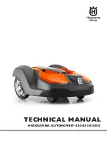
Husqvarna AUTOMOWER 420, Technical Manual
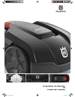
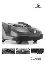
The Husqvarna AUTOMOWER 420 is an innovative and efficient robotic lawnmower designed to make your life easier. With its advanced technology, it can autonomously navigate and maintain your lawn, freeing up your time for more important things. Need a manual? Download the free Quick Manual from manualshive.com for easy setup and troubleshooting.
Share
Download


Reviews:
No comments