background image

English/French

586 69 21-01 Rev. 2

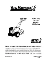
Owner’s Manual

Manuel du Propriétaire

917.250093

Gasoline containing up to 10% ethanol (E10) is accept-

able for use in this machine.  The use of any gasoline ex-

ceeding 10% ethanol (E10) will void the product warranty.
Vous pouvez utiliser de l’essence contenant jusqu’à 

10 % d’éthanol (E10) avec cet appareil.  L’utilisation 

d’essence contenant plus de 10 % d’éthanol annulera 

la garantie du produit.

Please read the owner's manual carefully and make sure 

you understand the instructions before using the machine.

Lisez très attentivement et soyez certain de comprende 

ces instructions avant d’utiliser cette machine.

Summary of Contents for 917.250093

Page 1: ...theproductwarranty Vous pouvez utiliser de l essence contenant jusqu à 10 d éthanol E10 avec cet appareil L utilisation d essence contenant plus de 10 d éthanol annulera la garantie du produit Please read the owner s manual carefully and make sure you understand the instructions before using the machine Lisez très attentivement et soyez certain de comprende ces instructions avant d utiliser cette ...

Page 2: ... stop the unit and disengage the controls quickly Never allow children to operate the equipment Never allow adults to operate the equipment without proper instruction Keep the area of operation clear of all persons par ticularly small children and pets PREPARATION Thoroughly inspect the area where the equipment is to be used and remove all foreign objects Disengage all clutches and shift into neut...

Page 3: ...s to service or repair this unit Please read and retain this manual The instructions will enable you to assemble and maintain your tiller properly Always observe the SAFETY RULES CUSTOMER RESPONSIBILITIES Read and observe the safety rules Follow a regular schedule in maintaining caring for and using your tiller Followinstructionsunder Maintenance and Storage sections of this Manual IMPORTANT THIS ...

Page 4: ...air of pliers 2 1 2 wrenches Your new tiller has been assembled at the factory with exception of those parts left unassembled for shipping purposes To ensure safe and proper operation of your tiller all parts and hardware you assemble must be tightened securely Use the correct tools as necessary to insure proper tightness OPERATOR S POSITION RIGHT FRONT LEFT Fig 1 4 Washers 3 8 x 7 8 x 14 6 Lock W...

Page 5: ...K CARTON INSTALL HANDLE See Fig 2 CAUTION Be careful of exposed staples when handling or disposing of cartoning material IMPORTANT WHEN UNPACKING AND ASSEMBLING TILLER BE CAREFUL NOT TO STRETCH OR KINK CABLE S Cut cable ties securing handles The handle may be assembled in high or low posi tion Slowly lift handle assembly up route cable s as shown and align handle holes with desired handle panel ho...

Page 6: ...ECOIL STARTER HANDLE DEPTH STAKE TINE SHIELD CHOKE CONTROL FORWARD TINE CONTROL REVERSE TINE CONTROL TINES THROTTLE CONTROL Fig 4 MEETS ANSI SAFETY REQUIREMENTS Our tillers conform to the safety standards of the American National Standards Institute CHOKE CONTROL Used when starting a cold engine DEPTH STAKE Controls forward speed and the depth at which the tiller will dig FORWARD TINE CONTROL Enga...

Page 7: ...d clevis pin Change wheel position Replace the hairpin clip and clevis pin For normal tilling set wheels at the second or third hole from the top HOW TO USE YOUR TILLER Know how to operate all controls before adding fuel and oil or attempting to start engine STOPPING See Fig 5 TINES Release forward tine control to stop forward move ment Release reverse tine control to stop reverse move ment ENGINE...

Page 8: ... open flame IMPORTANT WHEN OPERATING IN TEMPERATURES BELOW 32 F 0 C USE FRESH CLEAN WINTER GRADE GASOLINE TO HELP INSURE GOOD COLD WEATHER STARTING CAUTION Alcohol blended fuels called gaso hol or using ethanol or methanol can attract moisture which leads to separation and forma tion of acids during storage Acidic gas can damage the fuel system of an engine while in storage To avoid engine problem...

Page 9: ...on the climate rainfall and wind it may be advisable to till the soil at the end of the grow ing season to further condition the soil Soilconditionsareimportantforpropertilling Tineswill notreadilypenetratedry hardsoilwhichmaycontribute to excessive bounce and difficult handling of your tiller Hard soil should be moistened before tilling however extremely wet soil will ball up or clump during till...

Page 10: ...ngine run better and last longer BEFORE EACH USE Check engine oil level Check tine operation Check for loose fasteners LUBRICATION Keep unit well lubricated See LUBRICATION CHART MAINTENANCE SCHEDULE FILL IN DATES AS YOU COMPLETE REGULAR SERVICE Check Engine Oil Level Change Engine Oil Oil Pivot Points Inspect Air Screen Inspect Spark Arrester Muffler Clean or Replace Air Cleaner Cartridge Clean E...

Page 11: ...cording to your expected temperature NOTE Although multi viscosity oils 5W 30 10W 30 etc improve starting in cold weather these multi viscosity oils will result in increased oil consumption when used above 32 F 0 C Check your engine oil level more frequently to avoid possible engine damage from running low on oil Change the oil after every 50 hours of operation or at least once a year if the tille...

Page 12: ...e Fig 14 Your engine is air cooled For proper engine performance and long life keep your engine clean Clean air screen frequently using a stiff bristled brush Remove blower housing and clean as necessary Keep cylinder fins free of dirt and chaff MUFFLER Do not operate tiller without muffler Do not tamper with exhaustsystem Damagedmufflersorsparkarresterscould create a fire hazard Inspect periodica...

Page 13: ...ATH See Fig 17 Assemble holes A in tine hubs to holes C in tine shaft NARROW TILLING CULTIVATING 12 3 4 PATH See Fig 18 Remove outer tines TINE ARRANGEMENT Youroutertinescanbeassembledinseveraldifferentways to suit your tilling or cultivating needs CAUTION Tinesaresharp Weargloves orotherprotectionwhenhandlingtines NORMAL TILLING 26 PATH See Fig 16 Assemble holes A in tine hubs to holes B in tine ...

Page 14: ...ble up to remove slack and retighten clip TO REMOVE BELT GUARD See Fig 19 Remove two 2 cap nuts and washers from side of belt guard Loosen do not remove tine shield nut on underside of tine shield Pull belt guard out and away from unit Replace belt guard by reversing above procedure Be sure slot in bottom of belt guard is under head of tine shield bolt and all nuts are tightened securely SERVICE A...

Page 15: ...ET FOR PROPER ENGINE SPEED OVERSPEEDING THE ENGINE ABOVE THE FACTORY HIGH SPEED SETTING CAN BE DANGEROUS IF YOU THINK THE ENGINE GOVERNED HIGH SPEED NEEDS ADJUSTING CONTACT YOUR NEAREST AUTHORIZED SERVICE CENTER DEPARTMENT WHICH HAS THE PROPER EQUIPMENT AND EXPERIENCE TO MAKE ANY NECESSARY ADJUSTMENTS Fig 21 BELT GUIDE REVERSE IDLER PULLEY BELT GUIDE ENGINE PULLEY TRANSMISSION PULLEY FORWARD IDLER...

Page 16: ...eplace belts if necessary See belt re placementinstructionsintheServiceandAdjustments section of this manual Lubricate as shown in the Maintenance section of this manual Be sure that all nuts bolts and screws are securely fastened Inspect moving parts for damage breakage and wear Replace if necessary Touch up all rusted or chipped paint surfaces sand lightly before painting ENGINE FUEL SYSTEM IMPO...

Page 17: ...ill and clean carburetor 6 Stale or dirty fuel 6 Drain fuel tank and refill with fresh gasoline 7 Water in fuel 7 Drain fuel tank and carburetor and refill tank with fresh gasoline 8 Clogged fuel tank 8 Remove fuel tank and clean 9 Spark plug wire loose 9 Connect and tighten spark plug wire 10 Dirty engine air screen 10 Clean engine air screen 11 Dirty clogged muffler 11 Clean replace muffler 12 C...

Page 18: ...6 11 73220500 Nut Hex 5 16 18 12 98000129 Nut Hex Flanged KEY PART NO NO DESCRIPTION 1 2 3 3 16 4 5 7 8 12 13 FT handle_assy_12 14 7 11 10 29 19 20 29 19 20 30 NOTE All component dimensions given in U S inches 1 inch 25 4 mm REPAIR PARTS HUSQVARNA TILLER MODEL NUMBER 917 250093 HANDLE ASSEMBLY 13 180847 Bolt Round Head 5 16 18 x 3 4 14 9209RX668 Panel Assembly 16 166381X498 Handle Double Bend RH 1...

Page 19: ...ion Flat 19 188502 Bolt Belt Guard 20 12000036 Ring Klip 21 751153 Locknut Hex 3 8 16 22 180522 Pulley Idler 23 580530002 Arm Idler 24 74780524 Bolt 3 8 16 x 1 1 4 25 106968X Shaft Idler Arm 26 73350500 Nut Hex Jam 5 16 18 29 109227X Pad Idler 30 23200404 Set Screw Socket Headless C P 1 4 20 x 1 4 31 101189L Sheave Engine 32 151223 Sheave Transmisison 33 155415 Washer 20 x 8 5 x 2 0 41 180307 Spri...

Page 20: ...h 10 4929H Pin Clevis 11 74780628 Bolt Hex Head 3 8 16 x 1 3 4 13 1951JX479 Support Depth Stake L H 15 5388JX004 Spring Stake 16 121117X Bolt Shoulder 17 193851X613 Wheel 19 9190RX479 Bracket Wheel 20 73680600 Nut Crownlock 3 8 16 21 74760516 Bolt Hex Head 5 16 18 x 1 22 73800500 Locknut Hex with Washer Insert 5 16 18 24 73970500 Locknut Hex Flanged 5 16 18 UNC 25 19171416 Washer 17 32 x 7 8 x 16 ...

Page 21: ...2 tine_ipb_3 KEY PART NO NO DESCRIPTION 1 583854602 Tine Outer R H 2 3146R Retainer Spring 3 583854402 Tine Inner R H 4 583854202 Tine Inner L H 5 583854501 Tine Outer L H 6 4929H Rivet Pan Head Drilled 1 4 Diameter REPAIR PARTS HUSQVARNA TILLER MODEL NUMBER 917 250093 TINE ASSEMBLY ...

Page 22: ...Grade 2 5 16 18 x 1 1 2 2 74780652 Bolt Hex Head 3 8 16 x 3 1 4 3 19131311 Washer 13 32 x 13 16 x 11 5 73900600 Locknut Hex 3 8 16 6 9057RX668 Shield Tine 7 188195X479 Bracket Engine R H 8 165834X479 Bracket Engine L H 10 73970500 Nut Hex 5 16 18 11 187912 Bolt Hex Head 5 16 18 x 2 1 2 12 151222 Transmission 14 446548 Spacer Split 16 19091412 Washer 9 32 x 7 8 x 12 Gauge NOTE All component dimensi...

Page 23: ...0 Decal Control Forward 7 158701 Decal Control Reverse 8 120076X Decal Warning Rotating Tines 9 422972 Decal Tine Shield 13 423830 Decal Warning Ethanol E85 586692101 Manual Owner s English French REPAIR PARTS HUSQVARNA TILLER MODEL NUMBER 917 250093 DECALS 9 7 6 5 8 13 ...

Page 24: ...Warranty In most cases these items are NOT manufactured by Husqvarna in which case they may be covered separately by their respective manufacturer s warranties if one is provided and included with the product at the time of purchase The following transmission transaxle manufacturers Dana Hydro Gear Tuff Torq provide a warranty for the transmission transaxle to the ultimate purchaser or to Husqvarn...

Page 25: ...onal problem or failure occurs 9 Reinforced Stamped Armor Protected 10 Year Limited Fabricated Limited Lifetime Deck Warranties These Limited Warranties are for the deck shell only mechanical components parts such as belts pulleys spindle housings bearings blades rods height adjusters caster anti scalp wheels are NOT covered The Limited Lifetime Warranty does not cover damage other than that resul...

Page 26: ...arranty 10 Years No Warranty No Warranty Fabricated Deck shell Limited Lifetime Warranty No Warranty No Warranty Battery 1 Year Pro rated No Warranty No Warranty Other Non Expendable Components 3 Years 1 Year No Warranty LE475 Edger Tillers Snow Throwers Engine Other Non Expendable Components 2 Years 90 days 90 days Tiller Tines No Warranty No Warranty Walk Behind Mowers High Wheel Trimmer Engine ...

Page 27: ... left Consumer Commercial Rental Armor Protected Stamped Deck Shell Example Below Fabricated Deck Shell Example Below Stamped Deck Shell below NOT reinforced Limited Lifetime Warranty on Tiller tines and Fabricated Deck shell is for the life of the product or 7 seven years after the last date of the complete unit s final production whichever comes first Deck Shell replacement will be limited to a ...

Page 28: ...28 SERVICE NOTES ...

Page 29: ...lumage et maintenez le au loin de la bougie pour éviter le démarrage accidentel du moteur Débranchez le cordon d alimentation sur les moteurs électriques Ne démarrez pas le moteur à l intérieur d un bâtiment Les gaz d échappement sont dangereux N utilisez jamais votre motobineuse sans les déflecteurs les plaques de protection ou les autres dispositifs de sécurité en place Éloignez les enfants et l...

Page 30: ...TE MACHINE EST MUNI D UN MOTEUR À COMBUSTION INTERNE ET NE DEVRAIT PAS ÊTRE UTILISÉE OU PRÈS D UN TERRAIN COUVERT DES ARBRES DES ARBRISSEAUX OU DES HERBES SI LE SYSTÈME D ÉCHAPPEMENT N EST PAS MUNI D UN PARE ÉTINCELLES RENCONTRANT LES EXIGENCES DES LOIS LOCALES APPLICABLES QUAND UN PARE ÉTINCELLES EST UTILISÉ IL DEVRAIT ÊTRE MAINTENU EN BON FONCTIONNEMENT PAR L OPÉRATEUR VOIR LE CENTRE D ENTRETIEN...

Page 31: ...fond Utilisez les bons outils LES OUTILS EXIGES POUR LE MONTAGE Un jeu des clés à douille facilitera l assemblage Les dimensions normales des clés sont indiquées 1 Couteau à tout usage 1 Tournevis 1 Pince 2 Clés de 1 2 POSITION D OPERATEUR Voir la Fig 1 Quand on utilise l expression droite ou gauche l utilisateur est en position derrière le guidon 4 Rondelles 3 8 x 7 8 x 14 6 Rondelles Frein 5 16 ...

Page 32: ...STALLER LE MANCHE Voir la fig 2 ATTENTION Faites attention aux agrafes du carton IMPORTANT LORSQUE VOUS DÉBALLEZ OU MONTEZ LA MOTOBINEUSE NE PAS ÉTIRER OU ENTORTILLER LE S CÂBLE S Coupez les attaches qui fixent le manche Le guidon peut être monté dans la position haute ou basse Doucementlevezl ensembleduguidonenhaut et alignez les trous du guidon avec le trou et la fente du panneau du guidon Lâche...

Page 33: ...t de commander la vitesse de moteur COMMANDE DES FRAISES EN MARCHE AVANT permet d engager les fraises vers l avant JAUGE DE PROFONDEUR commandelavitesselaprofondeur auquelle la motobineuse bêche POIGNÉE DE DÉMARRAGE permet de démarrer le moteur JAUGE DE PROFONDEUR COMMANDE DES FRAISES DE MARCHE ARRIÈRE COMMANDE DES FRAISES EN MARCHE AVANT POIGNÉE DE DÉMARRAGE COMMANDE DE L ÉTRANGLEUR MANETTE DE CO...

Page 34: ... l axe de chape Réglez les roues au deuxième ou troisième trou du haut pour un labourage normal COMMENTUTILISERVOTREMOTO BINEUSE Assurez vousdeconnaîtretouteslescommandesavantd ajouter l essence l huile ou avant de démarrer le moteur ARRÊT Voir la Fig 5 FRAISES Relâchez la commande des fraises pour arrêter le mouve ment Relâchez la commande des fraises marche arrière pour arrêter le mouvement MOTE...

Page 35: ...ition des vapeurs d essence N en mettez pas trop Essuyez toujours l huile ou l essence ren versée Vousnedevezjamaisemmagasiner répandreouutiliserdel essenceprèsd une flamme nue IMPORTANT POUR ASSURER UN BON DÉMARRAGE PAR TEMPS FROID SOUS LES 32 F 0 C VOUS DEVEZ UTILISER DE L ESSENCE FRAÎCHE PROPRE ET SPÉCIALE D HIVER ATTENTION L expérience indique que les combus tibles mélangés avec l alcool appel...

Page 36: ...urage Attendez jusqu à ce que la terre soit moins mouillé afin d obtenir les meilleurs résultats Lorsque le labourage se fait à l automne enlevez les vignes et les longues herbes pour empêcher celles ci de s enrouler autour de l arbre des fraises et ralentir le labourage Vous trouverez le labourage beaucoup plus facile si vous laissez un rang non bêché entre les sillons Puis retournez entre les si...

Page 37: ...uile de moteur Vérifiez le fonctionnement des fraises Vérifiez la solidité des systèmes de fixation LUBRIFICATION Assurez que votre motobineuse est bien lubrifiée Reportez au TABLEAU DE LUBRIFICATION CALENDRIER D ENTRETIEN INSCRIVEZ LES DATES AU FUR ET À MESURE QUE VOUS EFFECTUEZ LES ENTRETIENS RÉGULIERS Vérifiez le niveau d huile de moteur Changez l huile de moteur Huilez les points de pivotement...

Page 38: ... température prévue REMARQUE Bienqueleshuilesdemulti viscosité 5W30 10W30 etc améliorentledémarragepartempsfroid leurconsommation augmente à plus de 0 C Vérifiez le niveau d huile plus fréquem ment pour éviter l avarie du moteur lors de l utilisation avec un niveau d huile bas Changezl huiletousles50heuresd opérationouaumoinsunefois par an si la motobineuse est utilisée moins de 50 heures par an V...

Page 39: ...s les 50 heures d utilisation ou au commencement de la saison de labourage Le type de la bougie d allumage et le réglage de l écart se trouvent dans la section de SPÉCIFICATIONS DU PRODUIT TRANSMISSION Votre transmission est scellée et la lubrification n est pas deman dée à moins qu elle soit réparée NETTOYAGE Ne pas nettoyer la motobineuse si le moteur et la transmission sont encore chauds Il ser...

Page 40: ... 24 61cm Voir la Fig 17 Montez les trous A dans les moyeux de fraise aux trous C dans l arbre de fraise LABOURAGE BINAGE ÉTROIT CHEMIN DE 12 75 32cm Voir la Fig 18 Enlevez les fraise extérieures REMARQUE Lorsderemontagedesfraisesextérieures assurez vous que l ensemble de la fraise du côté droit de la motobineuse marqué R et l ensemble de la fraise du côté gauche marqué de L soient montés au bon cô...

Page 41: ...lumage pour éviter le démarrage pendant la vérification de l uti lisation des dents Pour assurer le bon fonctionnement des fraises le levier de commande des fraises en marche avant doit être contre le corps de commande et tout le mou doit être enlevé du fil intérieur du câble de commande quand cette commande est à la position ARRÊT OFF haute Si le levier et le câble sont lâches relâchez le collier...

Page 42: ...LS APPROPRIES POUR DES REPARATIONS NECESSAIRES VÉRIFIER L UTILISATION DES FRAISES Référez vous à la section de VÉRIFICATION DE L UTILISA TION DES DENTS dans cette section de ce manuel REMPLACER LE PROTECTEUR DE COURROIE Fig 21 GUIDE COURROIE POULIE DU GALET TENDEUR DE MARCHE ARRIÈRE GUIDE COURROIE POULIE DU MOTEUR POULIE DE LA TRANSMISSION POULIE DU GALET TENDEUR DE MARCHE AVANT POULIE DU GALET TE...

Page 43: ...les conduites d essence et le carburateur soient vides N utilisezjamaislesproduitsspéciauxpournettoyerlemoteur et le carburateur dans le réservoir d essence L emploi de ces produits pourrait causer des dégâts permanents REMARQUE Un agent stabilisant dans l essence est une option acceptable pour minimiser la formation des dépôts de gomme de carburant pendant l entreposage Ajoutez l agent à l essenc...

Page 44: ...Essence sale ou vieille 6 Vidangez l essence du réservoir et remplissez avec l essence fraîche 7 II y a d eau dans l essence 7 Vidangez l essence du réservoir et du carburateur et remplissez le réservoir avec l essence fraîche 8 Réservoir d essence bouché 8 Enlevez le réservoir d essence et nettoyez le 9 Fil de bougie d allumage est débranché 9 Branchez et serrez le fil de bougie d allumage 10 Tam...

Page 45: ...u H 5 16 18 12 98000129 Écrou H KEY PART NO NO DESCRIPTION PIÈCES DE RECHANGE TILLER DE HUSQVARNA MODEL NO 917 250093 ENSEMBLE DE LA POIGNÉE 13 180847 Boulon de Chariot 5 16 18 x 3 4 14 9209RX668 Panneau de Montage 16 166381X498 Guidon C D 19 188562 Levier de Commande des Dents 20 188555 Goupille de Pivot 29 12000059 Pince d arrêtoir 30 181580 Pince REMARQUE Toutes les dimensions sont données en p...

Page 46: ...vant 15 446054 Courroie Contraire 16 12000028 Bague De Fermeture 17 446048 Clé 18 151236 Réa Transmission Plat 19 188502 Boulon Protecteur de Courroie 20 12000036 Rondelle Clip 21 751153 Écrou Frein 3 8 16 22 180522 Poulie De Tension 23 58053002 Bras du galet tendeur 24 74780524 Boulon 3 8 16 x 1 1 4 25 106968X Arbre Bras du galet tendeur 26 73350500 Écrou 5 16 18 29 109227X patin du galet tendeur...

Page 47: ...xe de chape 11 74780628 Boulon H 3 8 16 x 1 3 4 13 1951JX479 Support Tasseau C G 15 5388JX004 Ressort Tasseau 16 121117X Boulon 17 193851X613 Roue 19 9190RX479 Support Roue 20 73680600 Écrou Frein 3 8 16 21 74760516 Boulon H 5 16 18 x 1 22 73800500 Écrou Frein avec Rondelle 5 16 18 24 73970500 Écrou Frein 5 16 18 UNC 25 19171416 Rondelle 17 32 x 7 8 x 16 Jauge PIÈCES DE RECHANGE TILLER DE HUSQVARN...

Page 48: ...rne C D 2 3146R Ressort de Retenue 3 583854402 Dent Intérieurs C D 4 583854202 Dent Intérieurs C G 5 583854501 Dent Externe C G 6 4929H Rivet PIÈCES DE RECHANGE TILLER DE HUSQVARNA MODEL NO 917 250093 DENTS REMARQUE Toutes les dimensions sont données en pouces É U 1 pouce 25 4 mm ...

Page 49: ...18 x 1 1 2 Cat 2 2 74780652 Boulon H 3 8 16 x 3 1 4 3 19131311 Rondelle 13 32 x 13 16 x 11 5 73900600 Écrou Frein 3 8 16 6 9057RX668 Protecteur des Dents 7 188195X479 Support Moteur C D 8 165834X479 Support Moteur C G 10 73970500 Écrou H 5 16 18 11 187912 Boulon H 5 16 18 x 2 1 2 12 151222 Transmission 14 446548 Entretoise 16 19091412 Rondelle 9 32 x 7 8 x 12 Jauge 20 2 3 1 5 6 8 11 16 17 21 10 7 ...

Page 50: ...1 Décalcomanie Commande des Marche Arrière 8 120076X Décalcomanie Avertissement Dents à Rotation 9 422972 Décalcomanie Protecteur des Dents 13 423830 Décalcomanie d avertissement d éthanol 586692101 Manuel du Propriétaire Anglais Français PIÈCES DE RECHANGE TILLER DE HUSQVARNA MODEL NO 917 250093 DÉCALCOMANIES 9 7 6 5 8 13 ...

Page 51: ...ont incluant les systèmes d entraînement ne sont pas couvertes par cette garantie limitée Dans la plupart des cas ces articles ne sont PAS fabriqués par Husqvarna auquel cas ils peuvent être couverts séparément par les garanties de leur fabricant respectif si elles sont fournies et accompagnent le produit au moment de l achat Les fabricants suivants de transmission boîte pont Dana Hydro Gear Tuff ...

Page 52: ...rvalles recommandés de graissage des dommages causés par l eau ou l humidité ou un entreposage inadéquat p Pulvérisateurs à pompage ou la pulvérisation de matériaux inflammables ou caustiques crépines absentes ou brisées q Utilisation prolongée d un produit lorsqu un problème de fonctionnement ou une défaillance initiale survient 9 Garanties limitées à vie de fabrication de 10 ans unité de coupe r...

Page 53: ...à vie e i t n a r a g e n u c u A e i t n a r a g e n u c u A Batterie e i t n a r a g e n u c u A e i t n a r a g e n u c u A a t a r o r p u a n a 1 e i t n a r a g e n u c u A n a 1 s n a 3 s e l b a s i l i t u é r n o n s t n a s o p m o c s e r t u A Tranche gazon LE475 rotoculteurs souffleuses à neige Moteur Tondeuses Zero Turn usage résidentiel MZ Produit composant Tondeuses Zero Turn usag...

Page 54: ...t a c o L l a i c r e m m o C r u e t a m m o s n o C Exemples de coque d unité de coupe étampée protégée par armure ci dessous Exemple de coque d unité de coupe fabriquée ci dessous La Garantie à vie limitée sur les dents des rotoculteurs et de la coque fabriquée de l unité de coupe est pour la durée de vie utile du produit ou 7 sept années après la dernière date de la production complète finale ...

Page 55: ...55 REMARQUES D ENTRETIEN ...

Page 56: ...04 04 2014 BY ...

Reviews: