background image

Grass Catcher

54"

Model 966 445001

Operator's  Manual 2009-09


Summary of Contents for 115 247227 R1

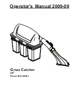
Page 1: ...Grass Catcher 54 Model 966 445001 Operator s Manual 2009 09 ...

Page 2: ... 2009 HTC All Rights Reserved Beatrice NE Printed in U S A ...

Page 3: ...fety 5 GENERAL OPERATION 5 SLOPE OPERATION 5 CHILDREN 6 SERVICE 6 Container Contents 8 Assembly 9 Operation 14 TIPS TO IMPROVE BAGGING 14 Customer Responsibilities 15 GENERAL RECOMMENDATIONS 15 STORAGE 15 Parts 16 ...

Page 4: ...R GRASS CATCHER Compare the illustrations with the carton contents to familiarize yourself with the parts before starting the assembly Study the operating instructions and safety precautions thoroughly to insure proper functioning of your Grass Catcher and to prevent injury to yourself and others Save this manual for future reference The operation of any mower can result in foreign objects thrown ...

Page 5: ... when operating near or crossing roadways Use extra care when loading and unloading the machine onto a trailer or truck Data indicates that operators age 60 years and above are involved in a large percentage of riding mower related injuries These operators should evaluate their ability to operate the riding mower safely enough to protect themselves and others from serious injury DO NOT operate mow...

Page 6: ...lways wear safety glasses or eye shields while operating your mower or performing any adjustments or repairs We recommend a wide vision safety mask over spectacles or standard safety glasses Use extra care in handling gasoline and other fuels They are flammable and vapors are explosive Use only an approved container Never remove gas cap or add fuel with the engine running Allow engine to cool befo...

Page 7: ...low speed while on slope or hill Avoid starting or stopping on a slope If tires lose traction disengage the blades and proceed slowly straight down the slope If machine stops while going uphill disengage blades shift into reverse and back down slowly Do not turn on slopes unless necessary and then turn slowly and gradually downhill if possible CAUTION In order to prevent accidental starting when s...

Page 8: ... CONTAINER CONTENTS 3 Soft Bag Containers 1 Upper Chute 1 Lower Chute 1 Catcher Hitch 1 Cover Assembly 1 Cast Weight 1 Catcher Mount Hardware COVER ASSEMBLY BAG CONTAINERS UPPER CHUTE DUMP BAG INDICATOR CHUTE LATCH LOWER CHUTE PARTS IDENTIFICATION CAUTION BEFORE ASSEMBLING GRASS CATCHER TO MOWER Place motion control levers in NEUTRAL position Set parking brake Turn ignition key OFF and remove key ...

Page 9: ...asten both bolts with flange nuts Repeat steps on opposite side NOTE The front side of the kit support straps should be on the inside of the mower frame Tighten all hardware 3 Reinforcement Plate Support Strap Drill rear guard hole to 5 16 if needed Remove rear engine guard if installed by removing the six bolts that attach the guard to the frame Place hitch on the rear of the mower 1 Rear Engine ...

Page 10: ...the cover assembly to mower Lift and rotate cover to align the cover brackets 1 with support assembly tubes Slide the cover down over the support tubes until 2 secure Remove plastic end caps from the center two bag support arms Fully insert spacer plugs into the ends of the support tubes It may be necessary to tap the spacers into place with a hammer or mallet Replace the plastic end cap back over...

Page 11: ...oking the latches to the mower deck 6LOWER CHUTE INSTALLATION Deflector Shield Deflector Bracket Tab Rear Latch Front Latch 5CONTAINER MOUNTING Install containers on supports overlapping at 1 center supports Close cover and lock latch handles over center 2 support tubes Center Support Tubes WARNING DO NOT operate mower unless container is properly installed Container is subject to wear and deterio...

Page 12: ...hute to secure 8CHUTE HOOD INSTALLATION Push upper chute through the gasketed opening 1 in the cover assembly Rotate chute so the chute opening is downwards 2 toward the container bags Hood Inlet 9LEVELING MOWER DECK Be sure deck is properly leveled for best mower performance See your mower operator s manual for instructions Rotate upper chute to point downwards towards bags 8063 051 8063 040 8063...

Page 13: ...of the frame 4 Secure the weight bracket to the frame with the 5 four previously removed bolts Install weight to the weight bracket with two 6 3 8 16 x 2 bolts and two 3 8 16 nuts from the new hardware Install foot rest on the weight bracket with six 7 10 12 x 1 and two 10 12 x 1 screws from the new hardware NOTE the shorter screws go in the center Cast Weight Weight Bracket Foot Rest CAUTION DO N...

Page 14: ...secure the top of the plastic lawn bag e Tip the container on its side and slide the filled bag from the container f Install a new plastic lawn bag with the edges of the bag draped over upper lip of the container g Repeat for other containers h Reinstall containers making sure containers overlap left at center supports i Close cover and secure latches over center support tubes Avoid cutting wet gr...

Page 15: ...DJUSTMENTS Place motion control levers in NEUTRAL position Set parking brake Place clutch control in DISENGAGED position Turn ignition key to OFF position Make sure blades and all moving parts have completely stopped Disconnect spark plug wire s from spark plug s and place wire where it cannot come in contact with plug CAUTION Do not leave grass in bagger containers Empty containers after each use...

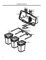
Page 16: ...16 REPAIR PARTS 1 2 4 6 7 8 9 10 11 5 12 3 3 12 ...

Page 17: ...09 1 1 SCREEN COVER 532 195373 2 1 COVER 539 976952 3 6 SCREW 10 24 x 5 8 539 108096 4 2 HAIR PIN 539 108097 5 4 PLUG TUBING END 532 176990 6 1 BAGGER FRAME 532 192786 7 2 PIN HINGE 532 192550 8 1 SEAL COVER 532 400226 9 3 CONTAINER SOFT BAG 532 192603 10 1 GASKET COVER 532 130895 11 2 HANDLE BAGGER COVER 539 976977 12 6 NUT 10 24 CROWNLOCK ...

Page 18: ...18 REPAIR PARTS 1 2 3 4 5 7 8 9 10 11 12 13 14 15 16 32 33 29 30 34 23 24 25 26 6 19 35 31 23 28 22 21 22 36 22 27 23 17 18 19 23 35 28 20 ...

Page 19: ...8 2 BOLT HEX 5 16 18 x 2 539 990627 19 4 BOLT HEX 5 16 18 x 1 539 110472 20 2 BOLT RD HD 5 16 18 x 1 539 101520 21 2 BOLT HEX 5 16 18 x 3 539 990188 22 10 WASHER 5 16 SAE 539 112899 23 10 NUT 5 16 18 FLANGE NYLOC 539 108447 24 1 DECAL CE 539 107899 25 4 BOLT HEX 5 16 18 x Gr8 539 990588 26 2 BOLT HEX 3 8 16 x 2 539 976979 27 2 Nut 3 8 16 nyloc 539 108089 28 3 PLATED WELD NUT 539 109552 29 3 LOCKWA...

Page 20: ... 782 1060 1410 1912 Grade 5 Minimum commercial quality lower quality not recommended Metric Standard Hardware Grade Grade 8 8 Grade 10 9 Grade 12 9 ft lbs ft lbs Nm ft lbs Nm ft lbs Nm M4 1 5 2 2 2 3 2 7 3 6 M5 3 4 4 5 6 5 2 7 M6 5 2 7 7 5 10 8 2 11 M7 8 2 11 12 16 15 20 M8 13 5 18 18 8 25 21 8 29 M10 24 32 35 2 47 43 5 58 M12 43 5 58 62 2 83 75 100 M14 70 5 94 100 133 119 159 M16 108 144 147 196 ...

Page 21: ......

Page 22: ......

Page 23: ......

Page 24: ...P N 115 247227 R1 06 15 09 ...

Reviews: