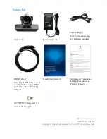
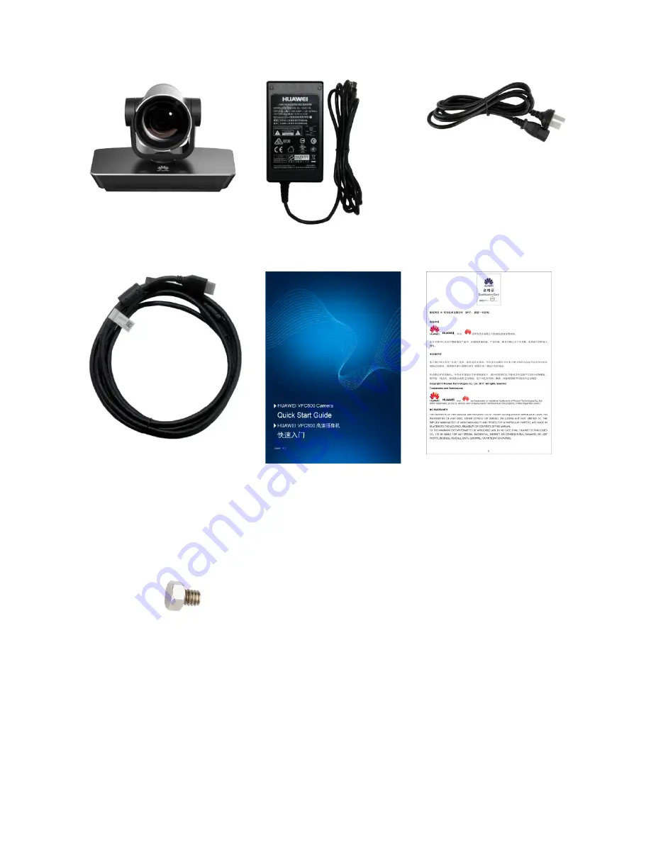
background image


Packing List 


Power cable (1) 
Note: Power cables may 
vary between countries.


Camera (1) 

Power adapter (1) 


HDMI cable (1) 
Note: The HDMI cable is used 

to connect the camera's HDMI 

port and a videoconferencing 

endpoint.   
 

Quick Start Guide (1) 

Certificate of Compliance 

& Safety Precautions & 

Warranty Card (1) 


1/4"-20UNC-7 mm screw (1) 
Used to fix a support. 


http://www.huawei.com 

Issue: 06 (2017-08-25) 

Copyright © Huawei Technologies Co., Ltd. 2017. All rights reserved. 

Summary of Contents for VPC800

Page 1: ... The HDMI cable is used to connect the camera s HDMI port and a videoconferencing endpoint Quick Start Guide 1 Certificate of Compliance Safety Precautions Warranty Card 1 1 4 20UNC 7 mm screw 1 Used to fix a support http www huawei com Issue 06 2017 08 25 Copyright Huawei Technologies Co Ltd 2017 All rights reserved ...

Page 2: ... information and then license information 1080p or 4K when a VPC800 is powered on Displays settings information when a VPC800 is running properly Displays the error code for a self check error or PTZ rotation error when an error occurs 6 Status indicator Indicates running sleep faulty and upgrade states 7 SELECT button Confirms the option of a parameter or moves to the next parameter 8 Power butto...

Page 3: ...fps 14 HD VI port Inputs serial control signals infrared signals and 12 V power Outputs digital visual interface DVI or YPbPr video signals 15 Network port Performs operations such as camera upgrade as well as camera angle adjustment upward downward left or right and image scaling zoom in or out through Telnet Installation The VPC800 can be mounted on top of a display such as TV set and monitor wa...

Page 4: ...4 Mounted on Top of a Display Use the L shaped bracket and its accessories to secure the VPC800 on top of the display The following figure shows the installation procedure ...

Page 5: ...river hammer and Phillips screwdriver by yourself Drill four holes in the wall for mounting the bracket each with a diameter of 8 mm 0 31 in and depth of 35 mm 1 38 in The two holes in the upper part must be parallel to the horizontal plane to ensure that the endpoint is horizontally installed Then follow the steps in the following figure to install the VPC800 ...

Page 6: ...6 ...

Page 7: ...UNC screw delivered with the purchased bracket rather than a 1 4 20UNC screw delivered with the VPC800 because the length of the latter may be too long or too short to hold up the purchased bracket Others Install the camera on a tripod separately purchased Powering the Camera On Connect the cables and power adapter to the camera and press the power button About 18 seconds later video is displayed ...

Page 8: ...ay the On Screen Display OSD configuration screen set RC to IR LOCAL or RF LOCAL On the screen you can define image related settings for example setting the image output format and enable or disable the image inversion mode The following table describes the keys on the remote control which are used to control the OSD configuration screen Key Description Press it twice to hide or display the OSD co...

Page 9: ...oint HD MODE STANDARD The video is displayed in standard mode If you select this option and set VEDIO to 720p 60 fps 1080p 30 fps 1080i 60 fps 1080p 60 fps 4K2Kp 30 fps and 4K2Kp 60 fps the actual video format are 720p 59 94 fps 1080p 29 97 fps 1080i 59 94 fps 1080p 59 94 fps 4K2Kp 29 97 fps and 4K2Kp 59 94 fps respectively By default HD MODE is set to STANDARD which is recommended FULL The video ...

Page 10: ... that the color output bit depth is 8 bit with the color gamut red green blue RGB being 256 x 256 x 256 The default value is 8 10 Indicates that the color output bit depth is 10 bit with the color gamut RGB being 1024 x 1024 x 1024 The color gamut for 10 bit depth is wider Notes 1 Press the SELECT button to scroll to RC VIDEO FLIP BIT DEPTH or HD MODE 2 Press the MODE button to select the desired ...

Page 11: ...s 720p 60 fps 1080p 1080p 50 fps 1080p 59 94 fps 1080p 60 fps 1080i 50 fps 1080i 59 94 fps 1080i 60 fps 1080p 25 fps 1080p 29 97 fps 1080p 30 fps 720p 50 fps 720p 59 94 fps 720p 60 fps Horizontal angle of view 6 3 TELE end to 72 WIDE end with a wide angle lens installed Diagonal angle of view 9 1 TELE end to 90 WIDE end with a wide angle lens installed Vertical angle of view 4 5 TELE end to 51 8 W...

Page 12: ...0 m with barriers Control angle 360 8 m without barriers Infrared remote control Infrared signal reception Comply with the following standards Control distance 6 m Vertical angle 15 Horizontal angle 30 Power and power supply Input voltage 100 240 V AC 50 Hz or 60 Hz Output voltage 12 V DC Power Operating 30 W Hibernation 2 W Physical specifications Control port rate 9600 baud Ambient temperature 0...

Page 13: ... faults contact an authorized maintenance center Position the device on stable surfaces only Keep the device or its accessories away from children Swallowing the accessories may be fatal Keep the power plug clean and dry to prevent electric shocks or other hazards Before cleaning the device shut it down and disconnect the power supply Do not press scratch or hit the lens and display with force Do ...

Page 14: ... cable of the power socket Question Why is the camera video not displayed on the display connected to the HD videoconferencing endpoint Answer The HD videoconferencing endpoint and camera are not connected correctly The input and output settings on the HD videoconferencing endpoint are incorrect The HD videoconferencing endpoint does not support the camera s video format The display does not suppo...

Page 15: ...Use a keyboard that supports the VISCA protocol to connect the cameras Connect the VISCA IN port of the first camera to the VISCA keyboard Then connect the VISCA OUT port of the first camera to the VISCA IN port of the second camera the VISCA OUT port of the second camera to the VISCA IN port of the third camera and so on A maximum of seven cameras can be connected in this serial connection mode T...

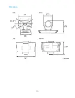
Page 16: ...16 Dimensions ...

Page 17: ...17 Pin Assignment No Pin VISCA IN Pin VISCA OUT 1 DTR NC 2 NC DSR 3 TXD TXD 4 GND GND 5 RXD RXD 6 GND GND 7 IR OUT NC 8 NC NC ...

Reviews: