

1
Issue: 03
Date: 2018-03-22
PowerCube 500 V200R001C10 Quick Guide
(PC500-300H1, PC500-300G1)
Copyright © Huawei Technologies Co., Ltd. 2018. All rights reserved.
1
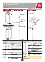
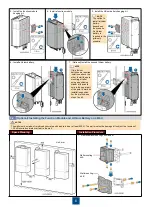
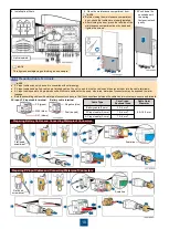
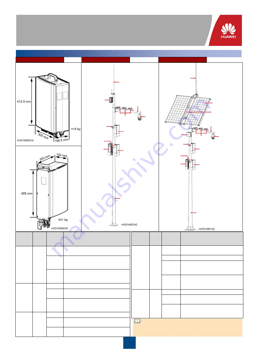
Overview
Function module: PC500-300H1,
PC500-300G1
Lithium battery: CBM20E-N14A1
Appearance
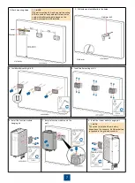
Grid Hybrid Scenario
Solar Hybrid Scenario
Lightning rod
PMP
microwave
Bullet
cameras
Dome
camera
Cantilever
Pole
mounting kit
Pole
mounting kit
Function
module
Lithium battery
Lithium battery
Pole
Lithium battery
Lithium battery
Function
module
Pole
mounting kit
Pole
mounting kit
Bullet
cameras
Dome camera
Lightning rod
PV modules
PV module
support
Pole
Cantilever
PMP
microwave
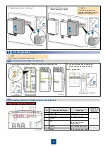
Lithium
Battery
Indicator
Color Status
Meaning
Run
indicator
(RUN)
Green
Off
The lithium battery has no power input
or is faulty.
Steady on The lithium battery is powered on.
Blinking
slowly
(0.5 Hz)
The lithium battery is communicating
properly with upstream monitoring
equipment.
Blinking
fast (4 Hz)
The lithium battery fails to
communicate with upstream
monitoring equipment.
Alarm
indicator
(ALM)
Red
Off
There is no alarm.
Steady on
The lithium battery has generated a
fault alarm and needs to be replaced.
Blinking
slowly
(0.5 Hz)
The lithium battery has generated a
protection alarm, which can be cleared.
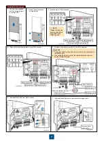
Function
Module
Indicator
Color
Status
Meaning
Run
indicator
Green
Off
The function module has no power input
or is faulty.
Blinking
slowly
(0.5 Hz)
The function module is communicating
properly with upstream monitoring
equipment.
Blinking
fast (4
Hz)
The function module fails to
communicate with upstream monitoring
equipment.
Alarm
indicator
Yellow
Off
There is no alarm.
Blinking
slowly
The function module has generated an
alarm, which can be cleared.
Steady
on
The function module has generated an
AC power failure or PV array fault alarm,
which can be cleared.
Fault
indicator
Red
Off
The function module is normal.
Blinking
slowly
The function module has an external
fault, which can be cleared.
Steady
on
The function module has an internal fault,
which cannot be cleared.
NOTE
The three indicators are steady on when the power unit of the
function module is upgrading. They return to normal status after the
upgrade is complete.


