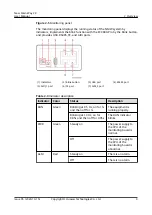
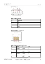
background image

New Main Way 2.0

User Manual

Issue

05

Date

2020-10-15

HUAWEI TECHNOLOGIES CO., LTD.

Part Number: 31500ACJ

Summary of Contents for New Main Way 2.0

Page 1: ...New Main Way 2 0 User Manual Issue 05 Date 2020 10 15 HUAWEI TECHNOLOGIES CO LTD Part Number 31500ACJ ...

Page 2: ...cribed in this document may not be within the purchase scope or the usage scope Unless otherwise specified in the contract all statements information and recommendations in this document are provided AS IS without warranties guarantees or representations of any kind either express or implied The information in this document is subject to change without notice Every effort has been made in the prep...

Page 3: ...allation engineers Commissioning engineers Data configuration engineers Maintenance engineers Symbol Conventions The symbols that may be found in this document are defined as follows Symbol Description Indicates a hazard with a high level of risk which if not avoided will result in death or serious injury Indicates a hazard with a medium level of risk which if not avoided could result in death or ...

Page 4: ...sonal injury Supplements the important information in the main text NOTE is used to address information not related to personal injury equipment damage and environment deterioration Change History Changes between document issues are cumulative The latest document issue contains all the changes made in earlier issues Issue 05 2020 10 15 Optimized the support installation diagrams Issue 04 2020 05 1...

Page 5: ...rio 17 3 2 2 Layout and Cable Routing Principles Dual Row Aisle Containment Crossing Rows 2N Scenario 18 3 2 3 Layout and Cable Routing Principles Dual Row Aisle Containment 2N Scenario 19 3 2 4 Layout and Cable Routing Principles Single Row Aisle Containment N 1 Scenario 20 3 2 5 Layout and Cable Routing Principles Dual Row Aisle Containment Crossing Rows N 1 Scenario 21 3 2 6 Layout and Cable Ro...

Page 6: ... 8 4 Replacing an SPD Circuit Breaker 60 8 5 Replacing the Auxiliary Contact of an SPD Circuit Breaker 61 8 6 Replacing an Integrated Management Card 63 8 7 Replacing the Monitoring Board of the General Input Unit 63 8 8 Replacing an Alarm Indicator 66 8 9 Replacing the Output Circuit Breaker of the Power Distribution Unit 67 9 Technical Specifications 71 A Preparing Load Cables 73 B Acronyms and ...

Page 7: ...tal to the local laws and regulations Personnel Requirements Personnel who plan to install operate and maintain Huawei equipment must be thoroughly trained understand all necessary safety precautions and master correct operation methods Only trained and qualified personnel are allowed to install operate and maintain the equipment Only personnel certified or authorized by Huawei are allowed to repl...

Page 8: ...atches when you operate the device In the case of a fire immediately leave the building or the equipment room and turn on the fire alarm bell or make an emergency call Never enter a building or equipment zone that is on fire Equipment Safety The device must be fixed securely on the floor or to other immovable objects such as walls or mounting racks before operation Do not block the ventilation ven...

Page 9: ...ween the core of a power cable and a conductor may generate electric arcs or sparks which may cause fire or hurt human eyes Before installing or removing a power cable turn off the power switch Before connecting a power cable check that the label on the power cable is correct Fuse CAUTION To ensure that the equipment runs safely if a fuse is blown replace it with a new fuse of the same type and sp...

Page 10: ...athing To ensure safety comply with the following requirements Power cables should be laid out or installed only when the temperature is higher than 0 C Cables stored at subzero temperatures must be stored at room temperature for at least 24 hours before they are laid out Handle power cables with caution especially at a low temperature Do not drop the power cables directly from the vehicle Pictu r...

Page 11: ...ive parts are not in contact with the exterior and that no foreign objects will enter the equipment during operation When the NMW baffle plate and cover are open and electrical wiring terminals are exposed by the electrical contractor or installation personnel who are setting up a power line connection it cannot be ensured that no foreign object will enter the NMW during onsite installation It is ...

Page 12: ...e NMW are beyond the warranty scope of Huawei The figures provided in this document are for reference only The actual product prevails Appearance Figure 2 1 Single route installation scenario 1 General input unit 2 Connective kit 3 Power distribution unit 4 Busbar trunking unit 5 Column 6 Around column busbar trunking unit and elbow used in the scenario with columns 7 End plug 8 Low support New Ma...

Page 13: ...rt 2 1 General Input Unit It is used as a cable entry unit Model Number Description Figure 2 3 General input unit No Meaning 1 New main way 2 Input MCCB current level 0250 250 A derated to 187 A at 40 C 0400 400 A derated to 300 A at 40 C 3 AC 4 Rated 380 415 V three phase 5 General input unit 6 Monitoring type 7 01 right mounted 02 left mounted New Main Way 2 0 User Manual 2 Overview Issue 05 202...

Page 14: ... on the monitoring panel is on the general input unit is powered by the mains 48 V or both If the PWR indicator on the monitoring panel is off the power supply is disconnected Table 2 2 Alarm indicator description without an integrated management card Status Description Steady on An alarm is generated the general input unit is powered by the mains and the 48 V power supply is not involved Off No a...

Page 15: ...or description Indicator Color Status Description RUN Green Blinking at 0 5 Hz on for 1s and then off for 1s The equipment is running properly Blinking at 10 Hz on for 0 05s and then off for 0 05s The RUN indicator blinks PWR Green Steady on The power supply to the CPU of the monitoring board is normal Off The power supply to the CPU of the monitoring board is abnormal ALM Red Steady on There is a...

Page 16: ... DP 4 GND Figure 2 7 RS485 FE and AIDI pins Table 2 5 RS485 FE and AIDI pin definition Pin RS485 FE AIDI 1 RS485 TRX0 2 RS485 TRX0 3 TRX1 GND 4 RS485 TRX2 5 RS485 TRX2 6 TRX1 GND New Main Way 2 0 User Manual 2 Overview Issue 05 2020 10 15 Copyright Huawei Technologies Co Ltd 10 ...

Page 17: ...FE communication extension It is hot swappable 1 PWR indicator 2 POE port 3 48 V output port Figure 2 9 POE pins Table 2 6 POE pin definition Pin Description 1 TRX0 _RTN 2 TRX0 _RTN 3 TRX1 _ 48V 4 TRX2 _RTN 5 TRX2 _RTN 6 TRX1 _ 48V New Main Way 2 0 User Manual 2 Overview Issue 05 2020 10 15 Copyright Huawei Technologies Co Ltd 11 ...

Page 18: ...nit Model Number Description Figure 2 10 Power distribution unit model No Meaning 1 New main way 2 Current level 125 A derated to 88 A at 40 C 3 AC 4 Rated 380 415 V three phase 5 Number of single phase circuit breakers 6 Number of three phase circuit breakers 7 Monitoring type 8 01 16 A output circuit breaker derated to 12 A at 40 C 02 40 A output circuit breaker derated to 30 A at 40 C 03 63 A o...

Page 19: ...FE port definitions of the power distribution unit and general input unit are the same Specifications Dimensions H x W x D 255 mm x 250 mm x 220 mm 2 3 Busbar Trunking Unit The busbar trunking unit consists of buses bus supports insulation parts the housing fasteners and connective kits connected to other units Model Number Description Figure 2 12 Busbar trunking unit New Main Way 2 0 User Manual ...

Page 20: ...ed to 300 A at 40 C 3 AC 4 Rated 380 415 V three phase 5 Busbar trunking unit 6 01 1200 mm long busbar trunking unit 02 407 mm long busbar trunking unit Appearance Figure 2 13 Busbar trunking unit New Main Way 2 0 User Manual 2 Overview Issue 05 2020 10 15 Copyright Huawei Technologies Co Ltd 14 ...

Page 21: ...ded cross sectional area mm2 L1 95 185 L2 95 185 L3 95 185 N 95 185 PE 50 95 Table 3 2 Input power cable terminal requirements Port Connection Method Bolt Specifications Recommended Bolt Length 250 A 3P 400 A 3P 250 A 3P 400 A 3P L1 Crimped DT terminal M12 35 mm 35 mm L2 Crimped DT terminal M12 New Main Way 2 0 User Manual 3 Installation Issue 05 2020 10 15 Copyright Huawei Technologies Co Ltd 15 ...

Page 22: ...ecommended cross sectional areas for single phase output power cables Output Switch 16 A 1P 40 A 1P 63 A 1P Recommended cross sectional area mm2 L 3 x 6 3 x 6 3 x 10 N PE When selecting connecting and routing power cables follow local safety regulations and rules When the external conditions such as cable routing mode or ambient temperature change perform verification in accordance with the IEC 60...

Page 23: ...t rPDU is A and the right rPDU is B 3 2 1 Layout and Cable Routing Principles Single Row Aisle Containment 2N Scenario There are two routes of NMWs routes A and B for each row of cabinets The number of power distribution units deployed on each route of the NMW should be the same If the power density per cabinet is less than or equal to 10 kW single phase power distribution units are used and each ...

Page 24: ...ion unit supports a maximum of six IT or network cabinets One power distribution unit provides three power outputs to the current row and another three power outputs to the corresponding cabinets in the other row If the power density per cabinet is greater than 10 kW three phase power distribution units are used and each power distribution unit supports a maximum of two IT or network cabinets One ...

Page 25: ... power distribution unit supports a maximum of six IT or network cabinets One power distribution unit provides six power outputs to route A and the other power distribution unit provides six power outputs to route B for the corresponding cabinets If the power density per cabinet is greater than 10 kW three phase power distribution units are used and each power distribution unit supports a maximum ...

Page 26: ...er cabinet is less than or equal to 10 kW single phase power distribution units are used and each power distribution unit supports a maximum of six IT or network cabinets One power distribution unit provides six power outputs to route A and the other power distribution unit provides six power outputs to route B for the corresponding cabinets If the power density per cabinet is greater than 10 kW t...

Page 27: ...o The number of power distribution units allocated to each row of cabinets must be an even number If the power density per cabinet is less than or equal to 10 kW single phase power distribution units are used and each power distribution unit supports a maximum of six IT or network cabinets One power distribution unit provides six power outputs to the cabinets in the current row and route A in the ...

Page 28: ...wer distribution unit provides six power outputs to route A and the other power distribution unit provides six power outputs to route B for the corresponding cabinets If the power density per cabinet is greater than 10 kW three phase power distribution units are used and each power distribution unit supports a maximum of two IT or network cabinets One power distribution unit provides two power out...

Page 29: ...tion unit which can be carried by one person Exercise caution to avoid slipping when climbing up and down stairs Handle with care when stacking NMWs The protection level of the NMW is IP30 No water pipes can be installed above the NMW including but not limited to the following chilled water supply and return pipes humidifier water supply pipes and condensate drainpipes New Main Way 2 0 User Manual...

Page 30: ...ons of general input units and power distribution units in the figures are for reference only The actual configuration prevails Figure 3 13 Maintenance inside the aisle skylights can be maintained Figure 3 14 Maintenance on both sides New Main Way 2 0 User Manual 3 Installation Issue 05 2020 10 15 Copyright Huawei Technologies Co Ltd 24 ...

Page 31: ...isle scenario 1 Rodent proof mesh 2 The fourth hole on the side of the first rodent proof mesh 3 Support Figure 3 16 Hot aisle scenario 1 Rodent proof mesh 2 The seventh hole on the side of the first rodent proof mesh 3 Support New Main Way 2 0 User Manual 3 Installation Issue 05 2020 10 15 Copyright Huawei Technologies Co Ltd 25 ...

Page 32: ...port Figure 3 18 Cold aisle 1200 mm deep cabinet 1 Rodent proof mesh 2 The second hole on the side of the first rodent proof mesh 3 Support Figure 3 19 Hot aisle 1 Rodent proof mesh 2 The second hole on the side of the second rodent proof mesh 3 Support New Main Way 2 0 User Manual 3 Installation Issue 05 2020 10 15 Copyright Huawei Technologies Co Ltd 26 ...

Page 33: ...ce on both sides If there are bolts in the holes for securing the supports remove the bolts and then secure the supports If the cabinet edges are uneven secure the supports to the higher cabinet edge and use a laser locator to ensure that the adjacent supports are flush in the front and rear directions Figure 3 20 Installation on the first cabinet 1 Door box 2 Rodent proof mesh 3 Support connectiv...

Page 34: ... covers from the general input unit Figure 3 22 Removing the covers Step 4 Secure the general input unit to the support Figure 3 23 Securing general input unit 1 New Main Way 2 0 User Manual 3 Installation Issue 05 2020 10 15 Copyright Huawei Technologies Co Ltd 28 ...

Page 35: ...iary lever is delivered place the MCCB auxiliary lever in the side fastener of the general input unit for switching on the circuit breaker when maintaining the general input unit Step 6 Install the busbar trunking unit Figure 3 25 Securing the busbar trunking unit New Main Way 2 0 User Manual 3 Installation Issue 05 2020 10 15 Copyright Huawei Technologies Co Ltd 29 ...

Page 36: ...E After inserting the connective kit into the busbar trunking unit ensure that the connective kit fully comes in contact with the copper bar You need to partially tighten the two bolts in the upper area of the connective kit and tighten the bolts after installing the protective covers In this example the torque for tightening M12 bolts on the connective kit is 45 N m For the actual torque see the ...

Page 37: ... sundries and dust Otherwise the internal copper bar may short circuit Step 10 Remove the protective cover from the busbar trunking unit NOTICE At least two protective covers are required between the power distribution units and between the power distribution unit and the general input unit Figure 3 28 Installing one power distribution unit 1 Position for removing the protective cover New Main Way...

Page 38: ...s for removing the protective covers Figure 3 31 Removing the protective cover from the busbar trunking unit Step 11 Install the power distribution unit Figure 3 32 Installing the power distribution unit Step 12 Install an end plug for the busbar trunking unit New Main Way 2 0 User Manual 3 Installation Issue 05 2020 10 15 Copyright Huawei Technologies Co Ltd 32 ...

Page 39: ...s row cable tray Step 14 Install the around column busbar trunking unit Skip this step in non column scenarios Figure 3 35 Installing the around column busbar trunking unit 1 Around column busbar trunking unit 2 Column 3 Support part Prepare support parts as required New Main Way 2 0 User Manual 3 Installation Issue 05 2020 10 15 Copyright Huawei Technologies Co Ltd 33 ...

Page 40: ...egrated management cards single row aisle containment 2N scenario NOTICE The following describes how to install integrated management cards in a single row aisle containment 2N scenario One integrated management card needs to be installed on the general input unit closest to the ECC Other integrated management cards need to be installed on the power distribution unit adjacent to the general input ...

Page 41: ...rfere with the cable trough or door Install a group of hanging rods every 600 mm Hanging rods cannot be installed around a column You need to adjust their locations The cables from the power distribution unit to the cabinet rPDU are not prefabricated and need to be prepared onsite For details see the appendix Preparing Load Cables Step 2 For details about how to install the NMW and cables see the ...

Page 42: ...Non cross row scenario 1 Extra low voltage ELV 2 Electrical Figure 3 39 Cross row scenario 1 ELV 2 Electrical New Main Way 2 0 User Manual 3 Installation Issue 05 2020 10 15 Copyright Huawei Technologies Co Ltd 36 ...

Page 43: ...urrent level is 250 A the No 1 bolt is M10 and the No 2 bolt is M12 If the input MCCB current level is 400 A the No 1 and 2 bolts are M12 Figure 3 41 Installing AC input power cables Step 3 If there is any gap around the rubber rings of the cables after the installation seal it from the inside using firestop putty Step 4 Reinstall the cover of the general input unit Figure 3 42 Installing the cove...

Page 44: ...o check whether it is loose If it is loose install it again NOTICE When a cable terminal is connected in place you will hear a click You need to install a ring buckle to fasten the cable terminal If not prefabricated the cables from the power distribution unit to the cabinet rPDU need to be prepared onsite For details see the appendix A Preparing Load Cables Table 3 5 Load cable silk screen Output...

Page 45: ... 48 V cascading cable needs to be prepared onsite ensure that the wire with a red tube is inserted into the terminal pin marked in red and the wire with a black tube is inserted into the terminal pin marked in blue New Main Way 2 0 User Manual 3 Installation Issue 05 2020 10 15 Copyright Huawei Technologies Co Ltd 39 ...

Page 46: ...put unit cabling Figure 3 45 Power distribution unit cabling Figure 3 46 Single Dual row aisle containment N 1 scenario New Main Way 2 0 User Manual 3 Installation Issue 05 2020 10 15 Copyright Huawei Technologies Co Ltd 40 ...

Page 47: ...ure 3 47 Single row aisle containment 2N scenario Figure 3 48 Dual row aisle containment 2N scenario New Main Way 2 0 User Manual 3 Installation Issue 05 2020 10 15 Copyright Huawei Technologies Co Ltd 41 ...

Page 48: ...on unit is flipped on Passed Failed 4 The end plug is installed Passed Failed 5 Load cables are connected correctly Power cables are reliably separated from signal cables Passed Failed 6 There is no foreign matter such as redundant cable ties paper and packing materials left around the new main way Passed Failed 7 Check that circuit breaker labels are correct clear complete and attached properly P...

Page 49: ...nges from 47 Hz to 53 Hz in the 50 Hz scenario or 57 Hz to 63 Hz in the 60 Hz scenario 4 1 Insulation Test Procedure Step 1 Check that the NMW has passed all check items of installation verification Step 2 Check that the upstream input and downstream output switches of the NMW are OFF Step 3 Remove the input protective cover Figure 4 1 Removing the input protective cover Step 4 Disconnect the term...

Page 50: ...reaker can be masked on the ECC800 Pro WebUI Procedure Step 1 Switch on the upstream input circuit breaker for the new main way Step 2 Switch on the SPD circuit breaker and input circuit breaker of the new main way and check that the PWR indicator on the monitoring panel is steady on Step 3 Switch on the network cabinet output circuit breaker in the power distribution unit of the new main way and ...

Page 51: ...ings for a general input unit Path Parameter Name Default Value Setting Monitoring Power Distribution General Input Unit Running Parameters Power Distribution Settings Rated system frequency 50 Set based on actual conditions Rated system voltage 380 Set based on actual conditions Rated system current This parameter is not displayed for some general input units 250 Set based on actual conditions Se...

Page 52: ... display two branches for power distribution unit 1 Choose Monitoring Power Distribution General Input Unit Power Distribution Unit Display Configuration select Branch Information Display corresponding to QF1 and QF2 and then tap Submit 3 Configure the power distribution settings for power distribution unit 1 Table 4 2 Power distribution settings for a power distribution unit Path Parameter Name D...

Page 53: ...wer distribution units in the same way or by synchronizing parameters Path Maintenance Parameter Sync Step 3 Determine the position of the general input unit or power distribution unit in the plan view of the WebUI Press the Blink button on the general input unit or power distribution unit for less than 1s to report the blinking status to the ECC800 Pro The corresponding device icon in the plan vi...

Page 54: ...ule Monthly Check the status of the indicator and miniature circuit breaker MCB of the surge protection module The surge protection module indicator is steady green The MCB is switched on Replace the surge protection module if its indicator is red If the MCB is switched off switch it on Connections of input and output power cables Monthly Visual observation Cables are intact The terminals are secu...

Page 55: ... RH Check that the air conditioner and dehumidifier in the equipment room function properly Dust on the surface of the new main way Quarterly Check whether there is dust on the surface of the new main way The white paper that you use to wipe the equipment is clean If the white paper is dirty clean the new main way New Main Way 2 0 User Manual 5 Routine Maintenance Issue 05 2020 10 15 Copyright Hua...

Page 56: ... are abnormal The monitoring board is faulty Check the cable connections If the cable connections are abnormal reconnect the cables If the cable connections are normal replace the monitoring board If the fault persists contact Huawei technical support The ALM indicator on the monitoring board is on An alarm is raised for the new main way The monitoring board is faulty Check the ECC800 alarm If an ...

Page 57: ... the power supply pin is short circuited Check whether the output is overloaded Check that the power supply pin is not short circuited 412177005 Detection board abnormal Critical The monitoring board hardware is faulty Check that no other alarm is generated for the monitoring board Replace the monitoring board 412177006 41217700 8 L1 L2 L3 open phase Critical Phase voltage is below the open phase ...

Page 58: ...2177018 41217702 0 L1 L2 L3 overloaded Critical The current exceeds the threshold Check the power of all output loads 412177027 41217702 9 Max L1 L2 L3 current exceed Major The current is greater than 80 of the rated current and less than the rated current Check the power of all output loads 412177036 41217703 8 Min L1 L2 L3 current exceed Major The current is greater than 60 of the rated current ...

Page 59: ...r distribution unit and ECC800 communication failure Attribute Major Communication with the PoE module is interrupted Check the cable connection to the power distribution unit 41218700 0 412187 003 POE1 POE2 POE3 POE4 output overload Major The output is overloaded or the power supply pin is short circuited Check that the output is not overloaded Check that the power supply pin is not short circuit...

Page 60: ...urrent exceed QF1 QF2 QF3 QF4 QF5 QF6 Warnin g The output current of the branch is greater than the configured threshold Check the power of the load on the corresponding branch 41218704 6 412187 051 Large current shock QF1 QF2 QF3 QF4 QF5 QF6 Major The output current of the branch is greater than the configured threshold Check that the insulation layer of the cable to the corresponding output bran...

Page 61: ...put switch and NTC are damaged replace the general input unit with a new one Procedure Step 1 Turn off the input switch and upstream power distribution switch and make a warning sign Step 2 Remove the communications cable and the DC power cable and mark the installation positions Step 3 Remove the integrated management card and install it on the new general input unit Figure 8 1 Removing the integ...

Page 62: ... and mark the installation position Step 6 Remove the connective kit between the general input unit and the busbar trunking unit Figure 8 3 Removing the connective kit Step 7 Remove the bolts and the general input unit Figure 8 4 Removing the bolts 1 Support fastener Step 8 Secure the new general input unit New Main Way 2 0 User Manual 8 Parts Replacement Issue 05 2020 10 15 Copyright Huawei Techn...

Page 63: ...ge select Delete device with communication failure click Submit and add the reserved device to the smart module view Step 18 Check the running status of the general input unit to ensure normal communication Step 19 Check that the power supply and distribution of the system are normal End 8 2 Replacing a Power Distribution Unit Prerequisites Tools step ladder Phillips screwdriver flat head screwdri...

Page 64: ...zation setting page is displayed Step 9 Click Device type and select the component type from the drop down list Step 10 Select the failed device in Source Device select the reserved device in Target Device and click Submit to synchronize the configuration parameters of the failed device to the reserved device Step 11 On the Monitoring System ECC800 Controls tab page select Delete device with commu...

Page 65: ...wer distribution switch of the general input unit and make a warning sign Step 2 Remove the communications cable and the DC power cable and mark the installation positions Step 3 Remove the protective covers and use a multimeter to check that the input terminal is not energized Figure 8 7 Removing the protective covers Step 4 Remove the protective cover Step 5 Loosen the buckle on the base and rem...

Page 66: ...ffected or obtain written consent from the customer Procedure Step 1 Turn off the input switch SPD circuit breaker and upstream power distribution switch of the general input unit and make a warning sign Step 2 Remove the communications cable and the DC power cable and mark the installation positions Step 3 Remove the protective covers and use a multimeter to check that the input terminal is not e...

Page 67: ...f the system are normal End 8 5 Replacing the Auxiliary Contact of an SPD Circuit Breaker Prerequisites Tools PDF door key step ladder Phillips screwdriver flat head screwdriver multimeter Material a new auxiliary contact of the same model Before the replacement ensure that the load services are not affected or obtain written consent from the customer Procedure Step 1 Turn off the input switch SPD...

Page 68: ...uxiliary contact and install the new auxiliary contact on the circuit breaker Figure 8 14 Removing the faulty auxiliary contact Step 7 Reinstall the circuit breaker and auxiliary contact and connect the cables Step 8 Reinstall the protective cover communications cable and DC power cable for the general input unit Step 9 Turn on the SPD circuit breaker upstream power distribution switch and input s...

Page 69: ...t card Figure 8 15 Removing the integrated management card Step 4 Insert a new integrated management card and lock it Step 5 Connect the communications cable and the DC power cable to the integrated management card End 8 7 Replacing the Monitoring Board of the General Input Unit Prerequisites Tools PDF door key step ladder Phillips screwdriver multimeter ESD bag ESD wrist strap Material a new moni...

Page 70: ...ck that the input terminal is not energized Figure 8 16 Removing the input protective covers Step 4 Remove the fuse from the monitoring board Figure 8 17 Removing the fuse from the monitoring board 1 Fuse holder Step 5 Remove cables from the monitoring board and mark the installation positions Step 6 Wear an ESD wrist strap remove the monitoring board and take ESD protection measures New Main Way ...

Page 71: ...ing page is displayed Step 12 Click Device type and select the component type from the drop down list Step 13 Select the failed device in Source Device select the reserved device in Target Device and click Submit to synchronize the configuration parameters of the failed device to the reserved device Step 14 On the Monitoring System ECC800 Controls tab page select Delete device with communication f...

Page 72: ...consent from the customer Procedure Step 1 Remove the communications cable and the DC power cable from the general input unit and mark the installation position Step 2 Remove the protective covers from the general input unit Figure 8 20 Removing the protective covers Step 3 Remove the fuse that protects power supply for the monitoring board Figure 8 21 Removing the fuse 1 Fuse 2 Indicator New Main...

Page 73: ...tion Unit Tools step ladder Phillips screwdriver flat head screwdriver extracting kit Material a new circuit breaker of the same model Non Hot Swap Circuit Breaker NOTICE During the replacement the output power of the power distribution unit is unavailable Before the replacement ensure that the load services are not affected or obtain written consent from the customer The procedure for replacing a...

Page 74: ...on unit Figure 8 24 Removing the power distribution unit Step 5 Remove the cover from the power distribution unit Step 6 Remove cables from the circuit breaker and mark the installation positions Step 7 Loosen the buckle on the circuit breaker base and remove the circuit breaker Figure 8 25 Loosening the buckle New Main Way 2 0 User Manual 8 Parts Replacement Issue 05 2020 10 15 Copyright Huawei T...

Page 75: ...properly End Hot Swappable Circuit Breaker Step 1 Turn off the faulty circuit breaker Step 2 Remove the protective cover from the circuit breaker Figure 8 26 Removing the protective cover Step 3 Push open the handles on both sides of the circuit breaker and remove the circuit breaker using an extracting kit NOTICE Remove and install the circuit breaker using an extracting kit Do not operate bareha...

Page 76: ...ting kit and close the handle Figure 8 29 Closing the handle Step 6 Reinstall the protective cover for the circuit breaker and turn on the circuit breaker Ensure that the power distribution unit works properly End New Main Way 2 0 User Manual 8 Parts Replacement Issue 05 2020 10 15 Copyright Huawei Technologies Co Ltd 70 ...

Page 77: ...0 m the equipment should be derated according to GB T 3859 2 93 The upper limit of the altitude is 4000 m Input system Three phase four wire PE Rated operating voltage V 380 V AC 400 V AC 415 V AC Input switch 250 A 3P derating coefficient 0 75 400 A 3P derating coefficient 0 75 IP rating IP30 Rated frequency 50 60 Hz New Main Way 2 0 User Manual 9 Technical Specifications Issue 05 2020 10 15 Copy...

Page 78: ... 2 x 16 A 3P 2 x 40 A 3P 2 x 63 A 3P Installation mode Installing on a cabinet top support or hanging no hanging kit is provided Certification CCC CE ASTA New Main Way 2 0 User Manual 9 Technical Specifications Issue 05 2020 10 15 Copyright Huawei Technologies Co Ltd 72 ...

Page 79: ...ree phase scenario is the same as that in the single phase scenario Figure A 1 Stripping a cable unit mm 2 Crimp a cord end terminal Figure A 2 Crimping a cord end terminal 1 Cord end terminal 2 Cable 3 Crimping tool 3 Optional For a three core cable with a cross sectional area of 6 mm2 wrap the cable with two layers of heat shrink tubing and use a heat gun to heat shrink the tubing New Main Way 2...

Page 80: ... rear cover 4 Insert cables into the round connector 5 Tighten the screws to secure each cable 6 Reinstall the rear cover 7 Optional Seal the holes where no cables are installed 8 Tighten the screw on the cable clip to the required torque Gaps are allowed on both sides of the cable clip Figure A 4 Installing cables at a round connector End New Main Way 2 0 User Manual A Preparing Load Cables Issue...

Page 81: ...CT current transformer F FE fast Ethernet M MCB miniature circuit breaker MCCB molded case circuit breaker R RS485 Recommend Standard 485 U New Main Way 2 0 User Manual B Acronyms and Abbreviations Issue 05 2020 10 15 Copyright Huawei Technologies Co Ltd 75 ...

Page 82: ...USB Universal Serial Bus New Main Way 2 0 User Manual B Acronyms and Abbreviations Issue 05 2020 10 15 Copyright Huawei Technologies Co Ltd 76 ...

Reviews: