background image

NetCol8000-E220 Modular Indirect Evaporative

Cooling System

User Manual

Issue

06

Date

2020-08-19

HUAWEI TECHNOLOGIES CO., LTD.

Summary of Contents for NetCol8000-E220

Page 1: ...NetCol8000 E220 Modular Indirect Evaporative Cooling System User Manual Issue 06 Date 2020 08 19 HUAWEI TECHNOLOGIES CO LTD ...

Page 2: ...cribed in this document may not be within the purchase scope or the usage scope Unless otherwise specified in the contract all statements information and recommendations in this document are provided AS IS without warranties guarantees or representations of any kind either express or implied The information in this document is subject to change without notice Every effort has been made in the prep...

Page 3: ...ngineers Data configuration engineers Maintenance personnel Symbol Conventions The symbols that may be found in this document are defined as follows Symbol Description Indicates a hazard with a high level of risk which if not avoided will result in death or serious injury Indicates a hazard with a medium level of risk which if not avoided could result in death or serious injury Indicates a hazard ...

Page 4: ...nges made in earlier issues Issue 06 2020 08 19 Updated the installation precautions Added the instructions for setting the system power limit parameter Updated the instructions for replacing a float Updated the electrical diagram Issue 05 2020 06 04 Updated the power wiring diagram Issue 04 2020 03 16 Optimized the Preparations and WebUI Login section Updated the water supply requirements Issue 0...

Page 5: ... 01 2019 05 31 This issue is the first official release NetCol8000 E220 Modular Indirect Evaporative Cooling System User Manual About This Document Issue 06 2020 08 19 Copyright Huawei Technologies Co Ltd iv ...

Page 6: ...Working Modes 19 2 4 Operating Environment Specifications 21 2 5 Technical Specifications 23 3 Installation Guide 25 3 1 Installation Precautions 25 3 2 Material Preparations 27 3 2 1 Optional Refrigerant R410A 28 3 2 2 Water Refill Pipe and Drainpipe 29 3 2 3 Pipe Support 30 3 2 4 Cable 30 3 3 Optional Concrete Platform Scenario 32 3 4 Optional Steel Base Scenario 36 3 5 Unpacking 40 3 5 1 Remove...

Page 7: ...creen 84 4 4 Initial Configuration 86 4 4 1 Setting Temperature and Humidity Values and Enabling T H Sensors 86 4 4 2 Setting Communications Parameters 88 4 4 2 1 Setting Communications Parameters Modbus RTU Protocol 88 4 4 2 2 Setting Communications Parameters Modbus TCP Protocol 89 4 4 2 3 Setting Communications Parameters SNMP Protocol 92 4 4 3 Optional Setting WIFI Parameters 96 4 4 4 Setting ...

Page 8: ...s 223 7 1 2 Querying Logs 224 7 1 3 Querying Component Status 224 7 1 4 Querying System Parameters 225 7 1 5 Querying Version Details 225 7 1 6 How to View Teamwork Control Information 225 7 1 7 How to View Teamwork Control Information 225 7 1 8 How Can I Handle Active Alarms 226 7 1 9 Deleting Historical Alarms 227 7 1 10 Deleting Logs 228 7 1 11 Clearing the Runtime 228 7 1 12 Calibrating a Sens...

Page 9: ...w Can I Change the Smart Cooling Product IP Address on the WebUI 241 7 2 7 How Can I View Version Information 242 A Cleaning the NetCol8000 E 243 B NetCol8000 E Repainting 244 C Parameter Description 249 D Maximum Water Consumption 267 E Cooling Component Layout 269 F Electric Diagram 270 G Acronyms and Abbreviations 276 NetCol8000 E220 Modular Indirect Evaporative Cooling System User Manual Conte...

Page 10: ...Follow local laws and regulations when installing operating or maintaining the equipment The safety instructions in this document are only supplements to local laws and regulations Huawei will not be liable for any consequences of the following circumstances Operation beyond the conditions specified in this document Installation or use in environments which are not specified in relevant internatio...

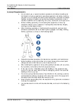
Page 11: ...lation operation and maintenance Before handling a conductor surface or terminal measure the contact point voltage and ensure that there is no risk of electric shock After installing the equipment remove idle packing materials such as cartons foam plastics and cable ties from the equipment area In the case of a fire immediately leave the building or the equipment area and turn on the fire alarm be...

Page 12: ... Before operations ensure that the equipment is firmly secured to the floor or other solid objects such as a wall or an installation rack Do not use water to clean electrical components inside or outside of a cabinet Do not change the structure or installation sequence of equipment without permission Do not touch a running fan with your fingers components screws tools or boards before the fan is p...

Page 13: ...nt installation operation maintenance Trained personnel personnel who are technically trained have required experience are aware of possible hazards on themselves in certain operations and are able to take protective measures to minimize the hazards on themselves and other people Operators operation personnel who may come in contact with the equipment except trained personnel and professionals Onl...

Page 14: ...between the cables and heat generating components or areas This prevents damage to the insulation layer of the cables Do not route cables behind the air intake and exhaust vents of the equipment Ensure that cables meet the VW 1 flame spread rating requirements Bind cables of the same type together When routing cables of different types ensure that they are at least 30 mm away from each other If an...

Page 15: ...allation Environment Requirements To prevent fire due to high temperature ensure that the ventilation vents or heat dissipation system are not blocked when the equipment is running Install the equipment in an area far away from liquids Do not install it under areas prone to condensation such as under water pipes and air exhaust vents or areas prone to water leakage such as air conditioner vents ve...

Page 16: ...restricted area and eye catching signs for working at heights to warn away irrelevant personnel Carry the operation machinery and tools properly to prevent them from falling off and causing injuries Personnel involving working at heights are not allowed to throw objects from the height to the ground or vice versa Objects should be transported by tough slings hanging baskets highline trolleys or cr...

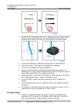
Page 17: ...en a step ladder is used ensure that the pull ropes are secured and the ladder is held firm Before using a ladder check that it is intact and confirm its load bearing capacity Do not overload it Ensure that the ladder is securely positioned The recommended angle for a ladder against the floor is 75 degrees as shown in the following figure An angle rule can be used to measure the angle Ensure that ...

Page 18: ...bles inside Metal shavings from drilling may short circuit boards inside the equipment Obtain the consent from the customer and subcontractor before drilling Wear goggles and protective gloves when drilling holes When drilling holes protect the equipment from shavings After drilling clean up any shavings that have accumulated inside or outside the equipment Moving Heavy Objects DANGER When removin...

Page 19: ...ystem Safety Welding At least two persons are required on a welding site A welder must have a work permit A welding site must be free from inflammables Ensure that a fire extinguisher wet wiper and water container are available A burning welding torch must not be placed on a component or on the floor and must not be placed in a metal container with acetylene and oxygen Otherwise the gas may leak a...

Page 20: ...th other wastes that have a shell in European Union EU areas To avoid environment pollution and harm to human health wastes must be classified and recycled This also promotes resource reuse When recycling a device fill in the device information in the recycling collection system or contact your dealer for help The dealer can help you recycle devices in a safe and environment friendly way 1 7 Other...

Page 21: ...ion Figure 2 1 NetCol8000 E model number description 2 2 Product Composition 2 2 1 Dimensions NetCol8000 E220 Modular Indirect Evaporative Cooling System User Manual 2 Product Description Issue 06 2020 08 19 Copyright Huawei Technologies Co Ltd 12 ...

Page 22: ... door 5 Condensate drainpipe 1 6 No 2nd maintenance door 7 Condensate drainpipe 2 8 Spray drainpipe 9 Spray water refill pipe 10 Outdoor air intake port on the side 11 No 3rd maintenance door NetCol8000 E220 Modular Indirect Evaporative Cooling System User Manual 2 Product Description Issue 06 2020 08 19 Copyright Huawei Technologies Co Ltd 13 ...

Page 23: ... port at the end 14 Indoor air return port 15 Indoor air return port 16 Condenser 17 Exhaust fan 18 Light 2 2 2 Physical Ports Table 2 1 Physical ports of air vent and water pipe Type Name Dimensions Quantity Air vent Outdoor air intake port at the end 2130 mm x 1310 mm 1 Outdoor air intake port on the side 500 mm x 1200 mm 2 Outdoor air outlet port 2130 mm x 1310 mm 1 NetCol8000 E220 Modular Indi...

Page 24: ...y AC2 input L1 1 AC2 input L2 1 AC2 input L3 1 AC2 input N 1 PE 1 Cooling power supply AC1 AC2 is needed generally If the compressor needs to be supplied separately additional AC3 is required AC3 input L1 1 AC3 input L2 1 AC3 input L3 1 AC3 input N 1 PE 1 Teamwork control monitoring external reserved ports AHU northbound monitoring RS485 1 AHU teamwork control CAN1 1 AHU teamwork control CAN2 1 Re...

Page 25: ... lists the relationship between alarm states indicators and buzzer If alarms of different severities critical major minor or warning are raised simultaneously the indicator status corresponds to the alarm with the highest severity level and the buzzer status corresponds to the unacknowledged alarm with the highest severity level Figure 2 5 Position of the indicator 1 Indicator 2 USBa Universal Ser...

Page 26: ...trol system LCD and temperature and humidity T H sensor to ensure its normal operating and high precision operating Operation display You can set parameters for the device and query its status on the 7 inch true color touchscreen Three remote functions Telemetry supply air temperature return air temperature supply air humidity return air humidity and working status of the unit Teleindication start...

Page 27: ...chscreen with a user friendly interface The controller is highly precise and responsive The controller is protected by a multi level password protection mechanism to avoid misoperation Password verification is required upon the first startup to ensure the system security No password verification is required for subsequent startup if the first verification succeeds The controller provides functions...

Page 28: ...5647 mm x 2020 mm x 840 mm 2 3 Working Modes Table 2 5 Cooling mode Cooling mode Fan Water pump Compressor Dry mode fan On Off Off Wet mode fan spraying On On Off Dry mode Auxiliary cooling mode fan compressor cooling On Off On Wet mode Auxiliary cooling mode fan spraying compressor cooling On On On NetCol8000 E220 Modular Indirect Evaporative Cooling System User Manual 2 Product Description Issue...

Page 29: ...Figure 2 7 Dry mode Figure 2 8 Wet mode NetCol8000 E220 Modular Indirect Evaporative Cooling System User Manual 2 Product Description Issue 06 2020 08 19 Copyright Huawei Technologies Co Ltd 20 ...

Page 30: ...tions Operating Environment Table 2 6 Operating environment Item Parameter Operating temperature 40ºC to 45ºC Operating humidity 5 95 RH Storage temperature 40ºC to 70ºC NetCol8000 E220 Modular Indirect Evaporative Cooling System User Manual 2 Product Description Issue 06 2020 08 19 Copyright Huawei Technologies Co Ltd 21 ...

Page 31: ...t 1 0 887 0 835 0 785 0 737 0 692 0 649 0 608 Note The sensible heat ratio is always 100 Installation Requirements NOTICE If the total actual load of servers for each smart cooling product is less than 10 of rated cooling capacity or the equipment room is not properly sealed the humidity in the equipment room may exceed the upper limit This is not a product quality issue and you are advised to add...

Page 32: ... pulsation and transient impulse current Note If the requirements are not met contact Huawei technical support for an optimized solution 2 5 Technical Specifications Table 2 9 System specifications Item Parameter Total refrigeration capacity 220 kW1 Sensible heat 220 kW1 Sensible heat ratio 100 Power specifications 380 415 V AC 3 Ph 50 Hz Air filter level on the air supply side of equipment room E...

Page 33: ...ed under rated working conditions return air 38ºC 25 RH indoor static pressure 150 Pa outdoor static pressure 50 Pa outdoor temperature 15 C Table 2 10 Compressor cooling parameters Item Parameter Cooling mode DX Added refrigerant percentage 50 Number of compressors 2 Compressor type Variable frequency Throttling components Electronic expansion valve EEV Refrigerant R410A NetCol8000 E220 Modular I...

Page 34: ...ulation panels may be deformed If the NetCol8000 is packed with the entire system do not stack them Check the NetCol8000 periodically Installation Clearances Reserve the following clearances around the device to facilitate operations and ventilation Reserve at least 500 mm from the return air side to the wall Reserve at least 1500 mm from the maintenance doors side to the wall or other device Rese...

Page 35: ...the dimensions width and depth of the NetCol8000 The surface of the concrete foundation is flat and clean Checking the drainage capacity There is a drainage ditch with sufficient drainage capacity around the foundation NOTICE The design and installation of the condensate water trap must meet the requirements shown in Figure 3 2 The layout and installation of water pipes facilitate the maintenance ...

Page 36: ...l8000 is not borne by the air channel Engineering air channels need to be supported to ensure that the air channels and NetCol8000 connections are not forced Pipe thermal insulation Take thermal insulation measures for all inlet and outlet pipes of the NetCol8000 Leave space for operating and maintaining thermal insulation for valves and joints Take insulation measures at low temperatures to preve...

Page 37: ...rigerant container and connect a pressure gauge to the container to measure its internal pressure Determine the saturation pressure that corresponds to the measured external surface temperature according to Table 3 1 and calculate the deviation from the measured internal pressure If the deviation is more than 0 2 MPa the refrigerant is not qualified and should be replaced Figure 3 3 Checking refri...

Page 38: ...9 35 2 04 54 3 26 17 1 23 36 2 1 55 3 34 18 1 27 37 2 15 N A N A 3 2 2 Water Refill Pipe and Drainpipe Table 3 2 Required water pipe specifications Name Connector Pipe Dimensions Material Quantit y Length Spray water refill pipe G 3 4 inch port with outer screw threads DN20 Rigid pipe made of PP R C PVC or other materials 1 Engineeri ng purchase Determin ed by the engineeri ng survey Spray drainpi...

Page 39: ...the pipe diameter including the thermal insulation foam Install a support every 2500 mm for the straight sections of pipes and 1000 mm away from each bending point in turning sections 3 2 4 Cable NOTICE Waterproof connectors are designed based on the cable specifications recommended in the table If the cables used onsite are inconsistent with the recommended specifications the cables may fail to p...

Page 40: ...obtains power from the standby power the maximum current of the standby power is 141A Recom mende d cross section al area L1 4 x 70 mm2 Optional L2 L3 N PE 35 mm2 Indoor unit cooling power cable Maximum current 70 A Optional This cable is required only when the compressor cooling system is powered independently Recom mende d cross section al area L1 4 x 70 mm2 L2 L3 N PE 35 mm2 NetCol8000 E220 Mod...

Page 41: ... is less than 1 Single or multi core 90 C soft power cables with copper conductors are used It is recommended that AC power cables be no longer than 30 m Table 3 4 Cable terminal requirements Item Connection Bolt Specificatio ns Torque Remarks Main power supply Crimped OT terminal M10 26N m Standard configuration delivered with the product Standby power supply Crimped OT terminal M10 26N m Standar...

Page 42: ...8000 E is within 5 degrees Lift and land a NetCol8000 E slowly to prevent shock to equipment inside it Remove the steel ropes after ensuring that the device is placed evenly on the concrete platforms Table 3 6 Parameters for hoisting NetCol8000 Es Weight Steel Rope Length Steel Rope Quantity Dimensions H x W x D Net weight 5700 kg 6 5 m 4 PCS 6058 mm x 2438 mm x 3600 mm Tools crane marker ink foun...

Page 43: ...e mounting positions for corner fittings ensure that the four lines form a rectangle Step 4 Adjust the NetCol8000 E in the required direction connect the steel hoisting ropes and hoist the NetCol8000 E onto the concrete platforms NOTICE When hoisting a NetCol8000 E ensure that the four corner fittings of the NetCol8000 E are aligned with the marked mounting positions for corner fittings on the con...

Page 44: ...he concrete platform using four right angle brackets Figure 3 7 Securing the equipment to the concrete platform End NetCol8000 E220 Modular Indirect Evaporative Cooling System User Manual 3 Installation Guide Issue 06 2020 08 19 Copyright Huawei Technologies Co Ltd 35 ...

Page 45: ...sting Precautions Stage Precautions Before hoisting Ensure that the crane and steel ropes provide the required bearing capacity The doors of NetCol8000 Es to be hoisted are closed Ensure that the steel ropes are securely connected Ensure that the weather condition is good without wind when NetCol8000 Es need to be hoisted outdoors During hoisting Do not allow any unauthorized people to enter the h...

Page 46: ...t weight 5700 kg 6 5 m 4 PCS 6058 mm x 2438 mm x 3600 mm Tools crane marker ink fountain long leather measuring tape socket wrench torque wrench Phillips screwdriver jack steel hoisting rope level level gauge hammer drill angle rule claw hammer vacuum cleaner Materials NetCol8000 E expansion bolt angle steel bracket Procedure Step 1 Prepare a steel base NetCol8000 E220 Modular Indirect Evaporative...

Page 47: ...ube 100 mm x 100 mm x 6 mm 4 Reinforced angle plate right angle edge 80 mm x 50 mm 15 mm thick 5 Expansion bolt M16 x 150 mm 6 14B channel steel NetCol8000 E220 Modular Indirect Evaporative Cooling System User Manual 3 Installation Guide Issue 06 2020 08 19 Copyright Huawei Technologies Co Ltd 38 ...

Page 48: ...hoist the equipment onto the base Figure 3 10 Hoisting the equipment Step 3 Turn the four M20 twistlocks in the base by 90 degrees to lock the equipment and tighten the twistlocks using a torque wrench NetCol8000 E220 Modular Indirect Evaporative Cooling System User Manual 3 Installation Guide Issue 06 2020 08 19 Copyright Huawei Technologies Co Ltd 39 ...

Page 49: ...s and concrete platforms Partially tighten them using a wrench Bolts and nuts are tightened 2 Contact between equipment and the base Observe The equipment is in close contact with and evenly supported by the base 3 Equipment doors Open and close each NetCol8000 E door once All NetCol8000 E doors can be smoothly opened and closed 3 5 Unpacking NetCol8000 E220 Modular Indirect Evaporative Cooling Sy...

Page 50: ...t and free of collision and scratch If any damage is found notify the carrier immediately Check the types and quantity of fittings against the fitting list If there is any problem contact Huawei technical support 3 5 3 Checking the Nitrogen Pressure Procedure Step 1 Open the No 2nd maintenance door Step 2 Check whether any of the needle valve bonnets shown in Figure 3 13 is missing by turns NetCol...

Page 51: ...uid pipe needle valve 2 4 Low pressure needle valve 2 End 3 6 Grounding the NetCol8000 E Ground lugs or ground cables can be used to ground the device Select either of the two options The requirements are as follows Ground lug use ground lugs made of hot dip zinc coated flat steel with a cross sectional area of 40 mm x 4 mm Ground cable Use 95 mm2 ground cables and route them through a plastic coa...

Page 52: ...ng lug Figure 3 15 Grounding cable 3 7 Installing a Supply Air Duct NetCol8000 E220 Modular Indirect Evaporative Cooling System User Manual 3 Installation Guide Issue 06 2020 08 19 Copyright Huawei Technologies Co Ltd 43 ...

Page 53: ...tall a Huawei supply air duct Procedure Step 1 Remove the pedal Figure 3 16 Removing the pedal Step 2 Remove the eight screws that fasten the air vent baffle and remove the air vent baffle NetCol8000 E220 Modular Indirect Evaporative Cooling System User Manual 3 Installation Guide Issue 06 2020 08 19 Copyright Huawei Technologies Co Ltd 44 ...

Page 54: ...e 3 18 Removing the duct fasteners Step 5 Secure the canvas sheet metal and canvas to the equipment using M6 screws NOTICE Ensure that there is no air leakage on the contact between the equipment and the air duct Otherwise condensate water may occur NetCol8000 E220 Modular Indirect Evaporative Cooling System User Manual 3 Installation Guide Issue 06 2020 08 19 Copyright Huawei Technologies Co Ltd ...

Page 55: ...p 6 Wrap the rubber plastic thermal insulation foam at least 3 cm thick covering the aluminum foil for the canvas Figure 3 20 Warping thermal insulation foam for the canvas Step 7 Use M12 screws to secure the air duct NetCol8000 E220 Modular Indirect Evaporative Cooling System User Manual 3 Installation Guide Issue 06 2020 08 19 Copyright Huawei Technologies Co Ltd 46 ...

Page 56: ...door installation scene Figure 3 22 Securing an air duct outdoor installation scene NetCol8000 E220 Modular Indirect Evaporative Cooling System User Manual 3 Installation Guide Issue 06 2020 08 19 Copyright Huawei Technologies Co Ltd 47 ...

Page 57: ... The return air duct needs to be prepared onsite The reserved space for the equipment is 2130 mm x 1310 mm You are advised to use foam boards Use six screws to secure the horizontal board and four screws the vertical board Drill holes at the return air vent by yourself Figure 3 23 Installing a return air duct unit mm 1 Flexible connection canvas or other materials prepared onsite 2 Hard connection...

Page 58: ...dimensions unit mm 1 PPR external thread connector G 3 4 inch 2 PPR equal diameter elbow 3 PPR pipe Φ25 mm NetCol8000 E220 Modular Indirect Evaporative Cooling System User Manual 3 Installation Guide Issue 06 2020 08 19 Copyright Huawei Technologies Co Ltd 49 ...

Page 59: ...exert excessive force to prevent damage to the coil pipe When connecting the pipes provided with the NetCol8000 use two pipe wrenches or chain pliers Take out the condensate water traps from attachment and install them to 1 2 and 3 in Figure 3 26 Use DN20 PPR pipes or stainless steel pipes and connectors G with 3 4 inch external threads onsite to prepare water inlet pipes If galvanized steel pipes...

Page 60: ...e active connectors and secure them using a wrench The drainpipe must be wrapped with thermal insulation foam including the buried parts and the thickness of the thermal insulation foam is not less than 3 cm Sealing 1 Remove the paper protective film from the sealing putty 2 Seal the gap between the water pipe and the equipment using sealing putty after the pipe is correctly connected NetCol8000 E...

Page 61: ...arting from the water refill and drain ports to the frozen soil layer Bury the remaining pipes underground the temperature at a specific depth underground is always above 0 C Figure 3 28 shows the anti freezing solution for water refill pipes and drainpipes in low temperature areas Figure 3 28 Pipe anti freezing solution 1 Trap 2 Electric heating belt NetCol8000 E220 Modular Indirect Evaporative C...

Page 62: ...e carried out one by one or simultaneously The following figure uses one system as an example Before vacuumizing the cooling system ensure that the refrigerant pipes have passed the air tightness test and do not leak Before vacuumizing the cooling system ensure that all connectors are secured System high pressure may occur if the cooling system is not vacuumized or is not thoroughly vacuumized Ens...

Page 63: ...system for at least 80 minutes after checking that the cooling system does not leak The pressure displayed on the vacuum pump should be less than or equal to 60 Pa absolute pressure When the pressure stops dropping pump for another 10 minutes The indication of sight glass is dry green Step 5 Close all the pressure gauge valves and the vacuum pump after vacuumizing the cooling system Preserve the p...

Page 64: ...d operations Charge refrigerant R410A right after checking that the cooling system does not leak and the vacuum level meets the requirements Procedure Step 1 Remove the vacuum pump from the vacuumizing equipment and replace the vacuum pump with a refrigerant cylinder as shown in Figure 3 31 Figure 3 31 Precharging refrigerant 1 Refrigerant cylinder 2 Electronic scale 3 Pressure gauge 4 Connection ...

Page 65: ...of refrigerant during power on commissioning Step 6 After refrigerant charging close pressure gauge valves and the refrigerant steel vessel valve NOTE After the injection is completed tighten the needle valve bonnet and check whether the needle valve leaks by applying soap bubbles to the valve vent or using a halogen leak detector If the valve leaks contact Huawei technical support End 3 12 Connec...

Page 66: ...iagram WARNING Keep away from device when preparing cables to prevent cable scraps such as iron chips copper wires and aluminum chips from entering the device Cable scraps may cause ignition during power on and result in personal injury and device damage After installing cables clean up the sundries inside the device electric control box copper cable and other positions Ensure that there is no dus...

Page 67: ...D2 22 Active power supply 23 Standby power supply 24 Cooling power supply 25 Signal cable terminals 26 Main control module 27 Backplane 28 Power Module 29 SPD and voltage detection board FV1 2 30 Electric heater of low temperature component 3 12 2 Connecting the Power Cable Procedure Step 1 Open the electric control box outside the device Step 2 Connect one end of the primary and secondary power c...

Page 68: ...sed the status of power inputs 3 and 4 is not detected End Exception Handling Generally only the active and standby power supplies are required The following figures show the power supply systems Figure 3 34 Power supply scenario 1 NetCol8000 E220 Modular Indirect Evaporative Cooling System User Manual 3 Installation Guide Issue 06 2020 08 19 Copyright Huawei Technologies Co Ltd 59 ...

Page 69: ...igure 3 36 Power supply scenario 2 If you need to connect the compressor cooling system to a third power supply remove the jumper from the power supply terminal of the compressor cooling system and connect the power input to the power supply terminal of the compressor cooling system NetCol8000 E220 Modular Indirect Evaporative Cooling System User Manual 3 Installation Guide Issue 06 2020 08 19 Cop...

Page 70: ...and shutdown signal and common alarm signal water sensor and micro differential pressure sensor can be connected to the NetCol8000 E The following operations use connecting a water sensor as an example NetCol8000 E220 Modular Indirect Evaporative Cooling System User Manual 3 Installation Guide Issue 06 2020 08 19 Copyright Huawei Technologies Co Ltd 61 ...

Page 71: ...oor RS485 Differential pressure sensor 3 Port for remote startup and shutdown N A GND 4 Port for remote startup and shutdown N A 12 V 5 Port 1 for reporting common alarms N A N A 6 Port 1 for reporting common alarms N A N A 7 Port 2 for reporting common alarms N A N A 8 Port 2 for reporting common alarms N A N A NetCol8000 E220 Modular Indirect Evaporative Cooling System User Manual 3 Installation...

Page 72: ...ar of the smart cooling product Figure 3 40 shows a main control module Figure 3 40 Main control module 1 FE_1 FE terminal 2 CAN_IN input port of the teamwork CAN northbound RS485 port 3 RS485 12 V T H module port 4 USB USB port 5 DP display port 6 COM FE northbound RS485 port 7 CAN_OUT output port of the teamwork CAN northbound RS485 port 8 FE_2 FE terminal 9 SW for restoring factory settings 10 ...

Page 73: ...ired onsite set Teamwork CAN resistor enable on Teamwork Settings of the first and last smart cooling products to Yes Step 1 Prepare the 8 pin standard network cable the cable pin sequence requirements are shown below Figure 3 41 CAN_IN CAN_OUT network cable pin sequence Step 2 Connect the CAN_OUT port of each smart cooling product to the CAN_IN port of the following smart cooling product using a ...

Page 74: ... Figure 3 43 Figure 3 43 Pin sequence of network cable NOTICE Except for pins 4 and 5 the cable of other pins must be cut off to prevent interference Step 2 Group smart cooling products for monitoring based on performance requirements and connect the monitoring network cables If there is no teamwork control connect the COM port on each smart cooling product to the customer s monitoring system Afte...

Page 75: ...ring group to Enable Setting path Settings Comm Settings Modbus Settings Figure 3 45 CAN networking and grouping End Connecting the FE Monitoring Network Cable SNMP Modbus TCP Protocol Step 1 Connect one end of the monitoring network cable standard network cable to the FE_1 port or FE_2 on the main control module and connect the other end to the monitoring device NetCol8000 E220 Modular Indirect E...

Page 76: ...idity They can be flexibly installed based on the onsite situation It is recommended that the sensors be deployed near heat sources or near places that lack cooling air Place the T H sensors outside the cabinet near the cabinet and do not directly face them to the air exhaust vent of the device Procedure Step 1 Connect the T H sensors outside the cabinet and the T H sensors at the air return side ...

Page 77: ...ive T H sensors in cold aisles and five T H sensors in hot aisles Step 2 Set the DIP switches of T H sensors Table 3 13 shows how to set the DIP switches for T H sensors Table 3 13 DIP switch setting on a T H sensor Locati on Display Name Addr ess DIP Switch Sequence No 1 2 3 4 5 6 Air return side Return air 2 temp humid 1 ON OFF OFF OFF OFF OFF Outdo or side Outdoor intake air 1 temp humid 31 ON ...

Page 78: ...OFF NOTICE The default addresses of T H sensors purchased from Huawei are 1 Keep the last RS485_R toggle switch at OFF After the addresses are set power on the device On the display s home screen choose Settings System Settings T H Sensor and set the sensors in the aisles corresponding to the addresses to Enable Otherwise the sensors will not work End 3 13 Removing the Transport Fasteners and Prot...

Page 79: ...que of 12 N m Step 4 Take out the two desiccant bags from No 2nd maintenance door Step 5 Open the No 1st maintenance door and take out the one desiccant bags from No 1st maintenance door Step 6 Remove the air filter from the air vent on the outdoor side and take out two desiccant bags from the device Figure 3 49 Position of the desiccants Step 7 Remove the elastic cord from the two floats NetCol80...

Page 80: ...p 8 Remove the protective covers from the four air filters on the outdoor air intake side NetCol8000 E220 Modular Indirect Evaporative Cooling System User Manual 3 Installation Guide Issue 06 2020 08 19 Copyright Huawei Technologies Co Ltd 71 ...

Page 81: ...filters need to be removed from outside Install air filters by referring to the direction instruction on the frame to ensure correct installation Step 9 Open No 3rd maintenance door remove the four screws from the air filter and remove the air filter NetCol8000 E220 Modular Indirect Evaporative Cooling System User Manual 3 Installation Guide Issue 06 2020 08 19 Copyright Huawei Technologies Co Ltd...

Page 82: ... items Check Item Expected Result Actual Result Cabinet The cabinet is installed properly without any tilts Passed Failed The foreign matter inside the cabinet such as desiccants cable ties stubs dust iron chips copper wires and aluminum chips are cleaned up Passed Failed Fan The fan is secured Passed Failed NetCol8000 E220 Modular Indirect Evaporative Cooling System User Manual 3 Installation Gui...

Page 83: ...ed Failed Water pan The foreign matter inside the water pan is cleaned up and water pan filter is not blocked Passed Failed Differential pressure switch The cable ties on the differential pressure tubes are secured Passed Failed There is no foreign matter in the differential pressure tubes The differential pressure tubes are not seriously bent Passed Failed Air filter The protective covers of the ...

Page 84: ...properly grounded Passed Failed Table 3 16 Pipeline checklist Expected Result Actual Result All pipes are secured reliably and steadily Passed Failed All pipes are wrapped with thermal insulation foam and the insulation foam is intact Passed Failed The water pipe joints are sealed by sealant Passed Failed Check that the needle valve plug is secured torque of 0 45 0 05 N m and valve bonnet is tight...

Page 85: ...ase sequence Step 4 If teamwork networking is required verify that the teamwork cable is correctly connected Step 5 If the cabinet is connected to the temperature and humidity sensor check that the cable connection and DIP switch settings are correct End 4 2 Power On Procedure Step 1 Turn on the upstream power input switch of the device The LCD lights up Step 2 After the system is powered on for t...

Page 86: ...arameters that cannot be modified by operator users otherwise Huawei will not be liable for any consequences of the unauthorized modification Only certified pros are allowed to modify the advanced parameters Unauthorized modifications may lead to device malfunction or damage For system security purposes change the preset password after first login After login you are allowed to perform operations ...

Page 87: ...urrent interface date format Date settings Specifies the date displayed on the ACC Consistent with the current interface date Time Specifies the time displayed on the ACC Consistent with the current interface time Time zone Specifies the time zone displayed on the ACC Consistent with the current interface time zone Settings Quick Settings Teamwork Settings Teamwork group No Set the assigned teamwo...

Page 88: ...etwork indicates teamwork control over a CAN bus MAC_CAN network teamwork control over an FE port CAN network Number of smart cooling products in this group Total number of the smart cooling products in this group 3 Number of running smart cooling products in this group The host allocates running units by smart cooling product unit address in ascending order which is from 1 to 32 The rest will bec...

Page 89: ...ended Disable Differential pressure sharing This parameter can be enabled when there are at least two smart cooling products in the group are configured with differential pressure sensors Disable Cold aisle temperature and humidity sharing This parameter can be enabled when there are at least two smart cooling products in the group are configured with cold aisle T H sensors Disable Hot aisle tempe...

Page 90: ...gerant leakage detection function You are advised to set this parameter to Enable Disable Compressor cooling The cooling function can be set to Enable or Enabled when active power Enable NetCol8000 E220 Modular Indirect Evaporative Cooling System User Manual 4 Power on and Commissioning Issue 06 2020 08 19 Copyright Huawei Technologies Co Ltd 81 ...

Page 91: ...contact close alarm if a major alarm is generated port 2 for reporting common alarms generates a dry contact close alarm When DO associated is set to Alarm startup status if an alarm is generated the dry contact of common alarm 1 is open If a startup status is generated the dry contact of common alarm 2 is close If a shutdown status is generated the dry contact of common alarm 2 is open When DO as...

Page 92: ...ed Hot aisle is not recommended Return air Temperature setpoint After the Temperature and humidity control type and the temperature value under this type are set the device runs based on the settings 25ºC Humidity setpoint After the Temperature and humidity control type and the humidity value under this type are set the device runs based on the settings 50 RH Cold aisle sensor 1 5 If a temperature...

Page 93: ... related screens or perform operations such as Running Alarms and Settings The controller main screen is shown in Figure 4 3 NOTICE User interfaces displayed in this document are for reference only Figure 4 3 Home screen Table 4 3 Note for the page No Items Note 1 Permission status indicates that you have not logged in to the system indicates that you have logged in to the system as an operator us...

Page 94: ...5 The current critical alarm and their quantity refers to the current critical alarm and their quantity 6 The current major alarm and their quantity refers to the current major alarm and their quantity 7 The current minor alarm and their quantity refers to the current major alarm and their quantity 8 The current warning alarm and their quantity refers to the current warning alarm and their quantit...

Page 95: ...o not enable the air damper function Otherwise the air damper communication failure alarm will be generated causing the device to work abnormally 4 4 1 Setting Temperature and Humidity Values and Enabling T H Sensors Prerequisites The T H sensors outside the cabinet need to be enabled when they are installed otherwise skip Step 2 If you need to enable a humidity and temperature sensor log in as th...

Page 96: ...ure and humidity set points correspond to the selected control type can be set When the application scenario is cold or hot aisle containment you are advised to choose Cold aisle if the cold aisle T H sensors are configured and choose Supply air if the cold aisle T H sensors are not configured When the application scenario is non aisle containment you are advised to choose Return air and choose Co...

Page 97: ...d humidity control type and the temperature value under this type are set the device runs based on the settings Set this parameter as required Return air temperature 26 35 C recommended Supply air temperature 18 24 C recommended Cold aisle temperature 18 24 C recommended Hot aisle temperature 26 35 C recommended Humidity setpoint After the Temperature and humidity control type and the humidity val...

Page 98: ...toring grouping Enable Disable For CAN networking and no grouping scenario set the RS485 monitoring grouping of the last smart cooling product to Enable For CAN networking and grouping scenario set the RS485 monitoring grouping of the last smart cooling product in each teamwork control group to Enable End 4 4 2 2 Setting Communications Parameters Modbus TCP Protocol Context This section applies to...

Page 99: ...able Figure 4 7 Modbus Settings 1 Figure 4 8 Modbus Settings 2 Step 3 Enter the actual IP address of the EMS Step 4 When Client encryption is set to Enable set NMS port number to 32907 when Client encryption is set to Disable set NMS port number to 32906 NOTE The encryption mode must be the same as it on the NMS NetCol8000 E220 Modular Indirect Evaporative Cooling System User Manual 4 Power on and...

Page 100: ...ion In addition the smart cooling product as a client can connect to a remote server and establish communication Client encryption Enable Disable This parameter is configurable when Link mode is set to Client Server encryption Enable Disable This parameter is configurable when Link mode is set to Server Encryption operation CBC Enable Disable Encryption operation CBC is enabled by default Determin...

Page 101: ... concurrent access of up to 6 EMSs through SNMP Procedure Step 1 On the home screen choose Settings Comm Settings SNMP Settings Figure 4 10 is displayed Figure 4 10 Setting SNMP communications parameters Step 2 Set SNMP Version based on site requirements and then tap Submit If you set SNMP Version to ALL or SNMPv1 v2c you can set Read Community and Write Community by performing Step 3 If you set S...

Page 102: ... values for Auth Protocol and Prop Protocol from drop down list boxes and tap as shown in Figure 4 13 MD5 and DES protocols are not secure It is recommended that you set Auth Protocol to SHA and set Prop Protocol to AES The following operations use the recommended settings as an example Figure 4 13 Setting the protocol type NetCol8000 E220 Modular Indirect Evaporative Cooling System User Manual 4 ...

Page 103: ...ontaining duplicate sections such as 12a12a12a 3 Set SHA Password and Confirm Password as planned and tap as shown in Figure 4 14 Figure 4 14 Setting an SHA password 4 Set AES Password and Confirm Password as planned and tap as shown in Figure 4 15 Figure 4 15 Setting an AES password 5 Tap Submit Step 5 Tap the text box after SNMP Port as shown in Figure 4 16 Set SNMP Port to the actual port numbe...

Page 104: ...o SNMPv3 select a SNMPv3 user name and then tap as shown in Figure 4 17 Figure 4 17 Setting SNMP trap parameters 5 Tap Submit under SNMP Trap End Follow up Procedure After a USB flash drive has been inserted into the controller USB port and successfully identified tap Export File under MIB File to export the MIB file to the USB flash drive for the customer s use in accessing a third party EMS Figu...

Page 105: ...le 4 7 Table 4 7 WiFi settings Parameter Setting Method WiFi SSID Set WiFi SSID based on the actual configuration WiFi SSID is the name used for the WiFi hotspot over which a mobile phone can connect to the smart cooling product WiFi Password Enter the WiFi password when you use a mobile phone to connect to the WiFi When you enable the WiFi function for the first time you need to set a password th...

Page 106: ... in this section are for reference only Set actually parameter values as required Procedure Step 1 On the home screen tap Teamwork Settings to enter Teamwork Settings page as shown in Figure 4 19 Figure 4 19 Teamwork settings Step 2 Set teamwork control parameters All teamwork control parameters can be set on the master smart cooling product Only Teamwork group No Smart cooling product address Ena...

Page 107: ...N network is used Set this parameter to No for non teamwork scenarios For teamwork scenarios set this parameter to Yes for the first and last smart cooling products in a teamwork group and set it to No for other smart cooling products No Teamwork function Disable or enable the teamwork function If the teamwork function is disabled this device is operating according to its own control If the teamwo...

Page 108: ...art cooling products in this group 3 Number of running smart cooling products in this group Number of active units in a group The value ranges from 1 to Number of smart cooling products in this group The host allocates running units by smart cooling product unit address in ascending order which is from 1 to 32 The rest will become the standby ones 2 Rotation function Disable or enable the active a...

Page 109: ...p before the specified rotation time After a forced rotation the accumulated time is recalculated This item is set to No by default If forced rotation is required the function is set to Yes No NetCol8000 E220 Modular Indirect Evaporative Cooling System User Manual 4 Power on and Commissioning Issue 06 2020 08 19 Copyright Huawei Technologies Co Ltd 100 ...

Page 110: ...t points of the master device and other parameters to the slave device and all the smart cooling products in the group refer to the mode delivered by the master device When the requirement control is Indoor fan unified control or Central load distribution all smart cooling product fans in the group rotate at the same speed Anti competitive running is recommended for the following scenario In one t...

Page 111: ...th the cold aisle T H sensor in the group is logically controlled by using the acquired value of the configured cold aisle T H sensor This parameter can be enabled when there are at least two smart cooling products in the group are configured with cold aisle T H sensors Disable Hot aisle temperatu re and humidity sharing When this parameter is enabled the smart cooling product which is not configu...

Page 112: ...d to be the new master 3 Active Standby Active properly responds to the requirement control Standby responds to the requirement control when active one is faulty critical alarms shutdown and offline or cannot meet cooling requirements 4 M S M indicates the master unit and S indicates a slave unit Blue indicates that the device is operating and gray indicates that the device is idle 5 Frame green n...

Page 113: ...connection and the settings of teamwork control parameters 2 Check whether the number of active devices on the topology is the same as the actual device number If yes go to 3 If no check the cable connection and the settings of teamwork control parameters 3 Check whether the number of standby devices on the topology is the same as the actual device number If yes go to 4 If no check the cable conne...

Page 114: ...value unless necessary If System power limit is set to an incorrect value the upstream power supply may be abnormal Prerequisites You need to log in as the admin user Procedure Step 1 On the home screen choose Settings System Settings System Control Step 2 Set Power limit function to Enable Figure 4 21 Setting the power limit function parameter Step 3 Tap the text box next to System power limit Ne...

Page 115: ...t System power limit and click Figure 4 23 Setting the system power limit parameter Step 5 Tap Confirm NetCol8000 E220 Modular Indirect Evaporative Cooling System User Manual 4 Power on and Commissioning Issue 06 2020 08 19 Copyright Huawei Technologies Co Ltd 106 ...

Page 116: ...ff status on remote is on by default The operations that start the smart cooling product successfully by the display button or by element management system EMS is effective only when the remote dry contact or On Off status on remote is on the status of on Prerequisites Download the Service Expert app from Huawei app store and runs on Android Apply for permission after downloading the app Step 1 Ta...

Page 117: ...OTICE If the initial startup verification is passed startup verification is not required afterwards After factory settings are restored re verification for startup is required Step 3 Tap StartUp on the home screen of the app and the screen shown in Figure 4 28 is displayed NetCol8000 E220 Modular Indirect Evaporative Cooling System User Manual 4 Power on and Commissioning Issue 06 2020 08 19 Copyr...

Page 118: ...ep 5 On the Offline Activation screen enter Bar code and Verification code which are available on the home screen of the ACC shown in Figure 4 25 Tap Generate PWD to generate a startup password NetCol8000 E220 Modular Indirect Evaporative Cooling System User Manual 4 Power on and Commissioning Issue 06 2020 08 19 Copyright Huawei Technologies Co Ltd 109 ...

Page 119: ...n Step 2 Choose Maint Diagnostic Mode Enter to enter the diagnostic mode Step 3 Set the compressor to 3000 rpm Step 4 Commission the compressor by setting the compressor rotational speed to 3000 rpm 1 Charge the rest of the refrigerant from the low pressure pipe needle valve in small flow or intermittently if possible The total amount of charged refrigerant must meet the requirements in requiremen...

Page 120: ... blockage would result in high discharge pressure Step 5 After charging refrigerant close all valves Step 6 Tap to exit the diagnostic mode Step 7 Tap Shutdown on the home screen and confirm it End 4 7 Wizard Startup Prerequisites Check that refrigerant is fully charged before performing the wizard startup Context The startup wizard allows for commissioning of components such as the indoor fan spr...

Page 121: ...ot allowed For the non initial startup wizard choose Last record and you can view the last startup wizard report Step 2 Tap Yes The checking before startup screen is displayed as shown in Figure 4 31 NOTICE If the remaining refrigerant is not charged tap No Complete refrigerant charging and then perform the wizard commissioning Figure 4 31 Checking before startup Step 3 Follow the onscreen instruc...

Page 122: ...iggered Step 3 Switch off the smart cooling product circuit breaker on PDC End 4 9 Checking After Commissioning Table 4 11 lists the commissioning checklist Table 4 11 Commissioning checklist Check Item Actual Result No oil stain exists on the copper pipe thermal insulation foam or bottom plate or it has been cleaned Passed Failed The needle valve plug is secured torque of 0 45 0 05 N m and valve ...

Page 123: ...t If the smart cooling product IP address is 192 168 0 10 subnet mask is 255 255 255 0 and default gateway is 192 168 0 1 set the PC IP address to 192 168 0 11 subnet mask to 255 255 255 0 and default gateway to 192 168 0 1 Step 4 Set LAN parameters NOTE If the smart cooling product connects to a LAN and a proxy server has been selected perform Step 4 3 and Step 4 4 If the smart cooling product co...

Page 124: ... Setting proxy server 5 Click OK Step 5 Log in to the WebUI of the smart cooling product 1 Enter https IP address such as IP address https 192 168 0 10 in the address box of the browser and then press Enter to enter the WebUI login page NetCol8000 E220 Modular Indirect Evaporative Cooling System User Manual 5 WebUI Issue 06 2020 08 19 Copyright Huawei Technologies Co Ltd 115 ...

Page 125: ...preset password Changeme select the language and click Log In NOTE Change the password after your first login An account is logged out due to timeout if no operation is performed within 10 minutes after system login End 5 2 WebUI Introduction For data transmission security the smart cooling product supports WebUI access through SSL NetCol8000 E220 Modular Indirect Evaporative Cooling System User M...

Page 126: ...page Figure 5 6 WebUI menu hierarchy NOTE The actual menu hierarchy prevails NetCol8000 E220 Modular Indirect Evaporative Cooling System User Manual 5 WebUI Issue 06 2020 08 19 Copyright Huawei Technologies Co Ltd 117 ...

Page 127: ...urity certificate Set the time zone time and date Set the IP address SNMP and NetEco network parameters Set the Modbus network parameters Set the SNMP network parameters Maintenance Upgrade the software of the smart cooling product and its sub components Query the version and e labels Query and export fault information Manage users for example adding and deleting a user Import and export configura...

Page 128: ...precautions and be able to correctly perform all operations Pay attention to the safety symbols on the equipment and all safety instructions in this document The safety precautions given in this document do not cover all safety precautions Huawei will not be liable for any consequence caused by violation of the safety operation regulations and design production and usage standards Most maintenance...

Page 129: ...d close the water discharge valve 30 minutes later Smart Cooling Product Maintenance The installation and maintenance of the smart cooling product must be periodically performed by trained personnel to ensure personal safety Take insulation measures for tools and human bodies before operating the smart cooling product When operating a fan do not insert your fingers or tools into the operating fan ...

Page 130: ...s Table 6 1 Final resistance value Filter Efficiency Recommended Final Resistance Pa G2 initial efficiency 50 100 G3 initial efficiency 100 200 G4 initial efficiency 150 250 F7 F8 medium and high efficiency 300 400 6 2 1 Monthly Maintenance Table 6 2 Monthly maintenance checklist Task Baseline Requirement Troubleshooting Air filter The air filter is clean and not blocked Clean the air filter on th...

Page 131: ...nd rewrap thermal insulation foam Wear protective gloves and touch the compressor angle valve Only for NetCol8000 E220DM0BA needle valve and soldering points in the refrigerant pipe to check whether there are oil stains If there is an oil stain check whether the suction and exhaust pressure of the compressor is within the normal ranges For the proper ranges of suction and exhaust pressure of the c...

Page 132: ...the compressor compartment push the upper door to the upper layer and enter the upper layer Pump Check whether the water pump is rusted Remove the rust 6 2 2 Quarterly Maintenance Table 6 3 Quarterly maintenance checklist Compo nent Item Monthly Maintenance Troubleshooting Monitor ing Export smart cooling product logs alarms temperature and humidity as well as the operating status and time of the ...

Page 133: ...1 C or humidity deviation is greater than 5 the T H sensor must be calibrated or replaced Heat exchange r The heat exchanger fins are not pushed down Use a fin brush to organize the fins that are pushed down Welding spot and needle valve Check that the welding spots and needle valves do not leak using soapy water or check that they are free from oil stains If leaking points are found retrieve the ...

Page 134: ...ompletely exhausted air blockage may occur and the water pump cannot spray normally In this case you need to manually exhaust the air When the water pump is running loosen the exhaust plug of the water pump When water flows out of the exhaust hole reinstall and tighten the exhaust plug Y type filter Clean the air filter in the Y type filter periodically Replace the Y type filter Figure 6 1 Drain v...

Page 135: ...exceeds the rated value on the nameplate The fan generates abnormal noise Great vibration occurs The temperature rise of the motor is too high One of the fans is faulty Cut off the power supply during maintenance to ensure safety NetCol8000 E220 Modular Indirect Evaporative Cooling System User Manual 6 System Operation and Maintenance Issue 06 2020 08 19 Copyright Huawei Technologies Co Ltd 126 ...

Page 136: ...overheated Check whether the air circulation is normal Clear foreign matters if necessary The fan blade is blocked or dirty Check the air inlet temperature Check the voltage The fan blade is blocked or dirty Power off the motor and prevent it from being connected again Check whether the motor is powered off Remove the protective grille Clear foreign matters or contaminants Reinstall the protective...

Page 137: ...ferent from the designed value Check the selected fan Vibration Imbalance Check whether the fan blades are damaged polluted or frozen Abnormal noise Bearing damage or wear Replace the bearing Fan blade friction collision Clear the foreign matters or dirt from the fan The fan is operating in the stall zone applicable to an axial fan Check whether the airflow is smooth air intake exhaust valve and a...

Page 138: ...ooling product and damaging the filtering materials Replace the air filter Electrical Control Perform routine check on all electrical components and safety devices Periodically check valves that control the flow of media Check whether the grounding devices of the electric devices are complete and functional Check the performance of safety protection devices such as circuit breakers and AC contacto...

Page 139: ... not have a water trap or does not meet the requirements Install or adjust the water trap The fan is not properly running The fan bearing is worn out Repair or replace the bearing The fan blade is interfered with the shell Adjust the fan blade The return air damper is shaking Adjust the return air damper There are foreign matters Clear the foreign matters The air volume is excessively large The ex...

Page 140: ... The drive is faulty Replace the drive The compressor discharge temperature is too high The refrigerant loop or component is blocked Clean foreign matters from the refrigerant loop Air enters the refrigerant loop Exhaust air and repair the pipeline Heat dissipation is poor because the condenser is dirty or blocked Clean the condenser fins The exhaust fan fails Check whether the exhaust fan works p...

Page 141: ... range Refrigerant oil is insufficient Add refrigerant oil The sheet metal for securing the compressor during transportation is not removed Remove the sheet metal The fan fails to start The switch of the fan is not turned on Check the switch of the fan The fan is damaged Replace the fan The interconnection terminals for the fan are not securely connected Secure the interconnection terminals The wa...

Page 142: ...amaged 2 The temperature sensor is faulty 1 Check the cables to the temperature sensor 2 Maintain or replace the temperature sensor A001 01 MAJOR Supply air 1 temperature sensor fault 1 The cables to the temperature sensor are loose or damaged 2 The temperature sensor is faulty 1 Check the cables to the temperature sensor 2 Maintain or replace the temperature sensor A001 01 MAJOR Supply air 2 temp...

Page 143: ...e temperature sensor are loose or damaged 2 The temperature sensor is faulty 1 Check the cables to the temperature sensor 2 Maintain or replace the temperature sensor A001 01 MAJOR Outdoor intake air 2 T H sensor fault 1 The cables to the temperature sensor are loose or damaged 2 The temperature sensor is faulty 1 Check the cables to the temperature sensor 2 Maintain or replace the temperature sen...

Page 144: ...icient or the supply water temperature is high 7 The chilled water valve is stuck or faulty 1 Adjust the positions of the temperature sensors or temperature and humidity sensors 2 Add air conditioners or contact Huawei technical support 3 Measure the ambient temperature Check whether other causes exist if the alarm persists in a long time after startup 4 Adjust the high temperature alarm threshold...

Page 145: ...ts in a long time after startup 4 Adjust the low temperature alarm threshold 5 Calibrate or replace the temperature sensor or temperature and humidity sensor 6 Maintain or replace the air filters 7 Maintain or replace the chilled water valve A007 01 MAJOR Return air 2 temp humid sensor comm failed 1 The cables to the temperature and humidity sensor are loose or damaged 2 The DIP switch of the temp...

Page 146: ...or 4 Maintain or replace the main control board A007 01 MAJOR Cold aisle 2 temp humid sensor comm failed 1 The cables to the temperature and humidity sensor are loose or damaged 2 The DIP switch of the temperature and humidity sensor is set incorrectly 3 The temperature and humidity sensor is faulty 4 The communications port of the main control board is faulty 1 Check the cables to the temperature...

Page 147: ...or 4 Maintain or replace the main control board A007 01 MAJOR Cold aisle 4 temp humid sensor comm failed 1 The cables to the temperature and humidity sensor are loose or damaged 2 The DIP switch of the temperature and humidity sensor is set incorrectly 3 The temperature and humidity sensor is faulty 4 The communications port of the main control board is faulty 1 Check the cables to the temperature...

Page 148: ...or 4 Maintain or replace the main control board A007 01 MAJOR Hot aisle 1 temp humid sensor comm failed 1 The cables to the temperature and humidity sensor are loose or damaged 2 The DIP switch of the temperature and humidity sensor is set incorrectly 3 The temperature and humidity sensor is faulty 4 The communications port of the main control board is faulty 1 Check the cables to the temperature ...

Page 149: ... humidity sensor is faulty 4 The communications port of the main control board is faulty 1 Check the cables to the temperature and humidity sensor 2 Set the DIP switch of the temperature and humidity sensor correctly 3 Maintain or replace the temperature and humidity sensor 4 Maintain or replace the main control board NetCol8000 E220 Modular Indirect Evaporative Cooling System User Manual 6 System...

Page 150: ...emperature and humidity sensor is faulty 8 The communications port of the main control board is faulty 1 Check the cables to the temperature and humidity sensor 2 Set the DIP switch of the temperature and humidity sensor correctly 3 Maintain or replace the temperature and humidity sensor 4 Maintain or replace the main control board 5 Check the cables to the temperature and humidity sensor 6 Set th...

Page 151: ...or 4 Maintain or replace the main control board A007 01 MAJOR Hot aisle 5 temp humid sensor comm failed 1 The cables to the temperature and humidity sensor are loose or damaged 2 The DIP switch of the temperature and humidity sensor is set incorrectly 3 The temperature and humidity sensor is faulty 4 The communications port of the main control board is faulty 1 Check the cables to the temperature ...

Page 152: ...exceed runtime alarm The accumulated runtime of the compressor exceeds the alarm threshold 1 Maintain or replace the compressor and clear the accumulated runtime A018 01 WARNI NG Indoor fan 1 exceed runtime alarm The accumulated runtime of the fan exceeds the alarm threshold 1 Maintain or replace the fan and clear the accumulated runtime A018 01 WARNI NG Indoor fan 2 exceed runtime alarm The accum...

Page 153: ...ntime of the fan exceeds the alarm threshold 1 Maintain or replace the fan and clear the accumulated runtime A018 01 WARNI NG Exhaust fan 5 exceed runtime alarm The accumulated runtime of the fan exceeds the alarm threshold 1 Maintain or replace the fan and clear the accumulated runtime A025 01 WARNI NG Return air filter blocked alarm 1 Air filters are blocked or dirty 2 The differential pressure ...

Page 154: ...ter exceeds the alarm threshold 1 Maintain or replace the air filter and clear the accumulated runtime A026 01 WARNI NG Outdoor intake air filter exceed runtime alarm The accumulated runtime of the air filter exceeds the alarm threshold 1 Maintain or replace the air filter and clear the accumulated runtime A027 01 WARNI NG Power loss alarm The power supply is cut off 1 If power failure occurs on t...

Page 155: ... cables to the remote shutdown dry contact are loose or damaged 1 Check the status of the remote shutdown dry contact 2 Check the cables to the remote shutdown dry contact A044 01 CRITICA L Smoke sensor alarm 1 Smoke is generated in the equipment room 2 The cables to the smoke sensor are loose or damaged 3 The smoke sensor is faulty 1 Expel smoke from the equipment room and reset the smoke sensor ...

Page 156: ...he indoor fan 6 Measure the ambient temperature A046 01 MAJOR Compressor 2 antifreeze protection alarm 1 The refrigerant leaks 2 The pressure displayed is different from the actual pressure 3 The filter dryer is blocked 4 The expansion valve is blocked or stuck or the expansion valve coil and cable connections are faulty 5 The indoor fan is faulty 6 The ambient temperature is below the lower thres...

Page 157: ...icient or the supply water temperature is high 7 The chilled water valve is stuck or faulty 1 Adjust the positions of the temperature sensors or temperature and humidity sensors 2 Add air conditioners or contact Huawei technical support 3 Measure the ambient temperature Check whether other causes exist if the alarm persists in a long time after startup 4 Adjust the high temperature alarm threshold...

Page 158: ... filters are blocked 7 The chilled water valve is stuck or faulty 1 Adjust the positions of the temperature sensors or temperature and humidity sensors 2 Contact Huawei technical support 3 Measure the ambient temperature Check whether other causes exist if the alarm persists in a long time after startup 4 Adjust the low temperature alarm threshold 5 Calibrate or replace the temperature sensor or t...

Page 159: ...icient or the supply water temperature is high 7 The chilled water valve is stuck or faulty 1 Adjust the positions of the temperature sensors or temperature and humidity sensors 2 Add air conditioners or contact Huawei technical support 3 Measure the ambient temperature Check whether other causes exist if the alarm persists in a long time after startup 4 Adjust the high temperature alarm threshold...

Page 160: ...emperature and humidity sensors 2 Add air conditioners or contact Huawei technical support 3 Measure the ambient temperature Check whether other causes exist if the alarm persists in a long time after startup 4 Adjust the high temperature alarm threshold 5 Calibrate or replace the temperature sensor or temperature and humidity sensor 6 Check the pressure and temperature of chilled water 7 Maintain...

Page 161: ...The cables to the pressure sensor are loose or damaged 2 The pressure sensor is faulty 1 Check the cables to the pressure sensor 2 Maintain or replace the pressure sensor A059 01 MAJOR Compressor 2 suction pressure sensor fault 1 The cables to the pressure sensor are loose or damaged 2 The pressure sensor is faulty 1 Check the cables to the pressure sensor 2 Maintain or replace the pressure sensor...

Page 162: ... fan is faulty 1 Maintain or replace the fan A077 02 MAJOR Indoor fan 4 fault The fan is faulty 1 Maintain or replace the fan A077 02 MAJOR Indoor fan 5 fault The fan is faulty 1 Maintain or replace the fan A077 02 MAJOR Indoor fan 6 fault The fan is faulty 1 Maintain or replace the fan A077 02 MAJOR Exhaust fan 1 fault The fan is faulty 1 Maintain or replace the fan A077 02 MAJOR Exhaust fan 2 fa...

Page 163: ...The fan is faulty 1 Maintain or replace the fan A077 04 MAJOR Exhaust fan 4 fault The fan is faulty 1 Maintain or replace the fan A077 04 MAJOR Exhaust fan 5 fault The fan is faulty 1 Maintain or replace the fan A077 04 MAJOR Exhaust fan 6 fault The fan is faulty 1 Maintain or replace the fan A077 08 MAJOR Indoor fan 1 fault The fan is faulty 1 Maintain or replace the fan A077 08 MAJOR Indoor fan ...

Page 164: ...The fan is faulty 1 Maintain or replace the fan A077 10 MAJOR Indoor fan 4 fault The fan is faulty 1 Maintain or replace the fan A077 10 MAJOR Indoor fan 5 fault The fan is faulty 1 Maintain or replace the fan A077 10 MAJOR Indoor fan 6 fault The fan is faulty 1 Maintain or replace the fan A077 10 MAJOR Exhaust fan 1 fault The fan is faulty 1 Maintain or replace the fan A077 10 MAJOR Exhaust fan 2...

Page 165: ...tion to the fan 2 Maintain or replace the fan A077 20 MAJOR Indoor fan 5 fault 1 The ground cable to the fan is not connected properly 2 The fan is faulty 1 Check the ground cable connection to the fan 2 Maintain or replace the fan A077 20 MAJOR Exhaust fan 1 fault 1 The ground cable to the fan is not connected properly 2 The fan is faulty 1 Check the ground cable connection to the fan 2 Maintain ...

Page 166: ...connected properly 2 The fan is faulty 1 Check the ground cable connection to the fan 2 Maintain or replace the fan A089 01 MAJOR Compressor 1 drive speed limit alarm 1 The compressor lacks oil 2 The refrigerant leaks 1 Fill oil to the compressor 2 Identify and repair the leaking point and refill refrigerant after maintenance A089 01 MAJOR Compressor 2 drive speed limit alarm 1 The compressor lack...

Page 167: ... filters are blocked 7 The chilled water valve is stuck or faulty 1 Adjust the positions of the temperature sensors or temperature and humidity sensors 2 Contact Huawei technical support 3 Measure the ambient temperature Check whether other causes exist if the alarm persists in a long time after startup 4 Adjust the low temperature alarm threshold 5 Calibrate or replace the temperature sensor or t...

Page 168: ...filters are blocked 7 The chilled water valve is stuck or faulty 1 Adjust the positions of the temperature sensors or temperature and humidity sensors 2 Contact Huawei technical support 3 Measure the ambient temperature Check whether other causes exist if the alarm persists in a long time after startup 4 Adjust the low temperature alarm threshold 5 Calibrate or replace the temperature sensor or te...

Page 169: ...idity alarm threshold 5 Calibrate or replace the temperature and humidity sensors A094 01 WARNI NG Low humidity alarm 1 The ambient humidity is below the lower threshold 2 The temperature and humidity sensor is not installed in a proper position 3 The low humidity alarm threshold is inappropriate 4 The value detected by the temperature and humidity sensor is different from the actual value 1 Measu...

Page 170: ...1 MAJOR Backup power failure alarm The power supply is faulty 1 Check the power supply A118 01 MAJOR Primary power failure alarm The power supply is faulty 1 Check the power supply A118 02 MAJOR Primary power failure alarm The power supply is faulty 1 Check the power supply A120 01 MAJOR Indoor fan 1 communicatio n failed 1 The communications cable to the fan is not connected properly 2 The fan is...

Page 171: ...tions cable to the fan is not connected properly 2 The fan is faulty 1 Check the communications cable connection to the fan 2 Maintain or replace the fan A120 01 MAJOR Exhaust fan 1 communicatio n failure 1 The communications cable to the fan is not connected properly 2 The fan is faulty 1 Check the communications cable connection to the fan 2 Maintain or replace the fan A120 01 MAJOR Exhaust fan ...

Page 172: ...2 The fan is faulty 1 Check the communications cable connection to the fan 2 Maintain or replace the fan A134 01 MAJOR Compressor 1 suction temperature sensor fault 1 The cables to the suction temperature sensor are loose or damaged 2 The suction temperature sensor is faulty 1 Check cables to the suction temperature sensor 2 Maintain or replace the suction temperature sensor A134 01 MAJOR Compress...

Page 173: ...board 3 Maintain or replace the main control board A174 01 MAJOR SPD function failure The SPD and voltage detection board is faulty 1 Replace the SPD and voltage detection board A174 01 MAJOR Backup SPD function failed The SPD and voltage detection board is faulty 1 Replace the SPD and voltage detection board A174 02 MAJOR SPD function failure 1 The SPD is faulty 2 The cable to the SPD is not conn...

Page 174: ...e system for leaking points If so repair the pipe and add refrigerant 2 Add refrigerant as required in the user manual 3 Calibrate or replace the liquid pipe temperature sensor or the condensing pressure sensor A193 01 MAJOR Air side diff pressure sensor fault 1 The differential pressure sensor cable is loose or damaged 2 The pressure tube of the differential pressure sensor is reversely connected...

Page 175: ...blade is stuck 2 The fan is faulty 1 Clear the blockage 2 Maintain or replace the fan A208 01 MAJOR Exhaust fan 3 blocked alarm 1 The fan blade is stuck 2 The fan is faulty 1 Clear the blockage 2 Maintain or replace the fan A208 01 MAJOR Exhaust fan 4 blocked alarm 1 The fan blade is stuck 2 The fan is faulty 1 Clear the blockage 2 Maintain or replace the fan A208 01 MAJOR Exhaust fan 5 blocked al...

Page 176: ...ir conditioner is shut down via the LCD or NetEco 1 Restart the air conditioner via the LCD or NetEco A26B 01 MAJOR Indoor fan 1 power supply abnormal 1 The cable to the fan is not connected properly 2 The fan is faulty 1 Check the cable connection to the fan 2 Maintain or replace the fan A26B 01 MAJOR Indoor fan 2 power supply abnormal 1 The cable to the fan is not connected properly 2 The fan is...

Page 177: ...1 The cable to the fan is not connected properly 2 The fan is faulty 1 Check the cable connection to the fan 2 Maintain or replace the fan A26B 01 MAJOR Exhaust fan 4 power supply abnormal 1 The cable to the fan is not connected properly 2 The fan is faulty 1 Check the cable connection to the fan 2 Maintain or replace the fan A26B 01 MAJOR Exhaust fan 5 power supply abnormal 1 The cable to the fan...

Page 178: ...ormal The fan is faulty 1 Maintain or replace the fan A26B 02 MAJOR Exhaust fan 4 power supply abnormal The fan is faulty 1 Maintain or replace the fan A26B 02 MAJOR Exhaust fan 5 power supply abnormal The fan is faulty 1 Maintain or replace the fan A26B 02 MAJOR Exhaust fan 6 power supply abnormal The fan is faulty 1 Maintain or replace the fan A26B 04 MAJOR Indoor fan 1 power supply abnormal 1 T...

Page 179: ... 1 The cable to the fan is not connected properly 2 The fan is faulty 1 Check the cable connection to the fan 2 Maintain or replace the fan A26B 04 MAJOR Exhaust fan 2 power supply abnormal 1 The cable to the fan is not connected properly 2 The fan is faulty 1 Check the cable connection to the fan 2 Maintain or replace the fan A26B 04 MAJOR Exhaust fan 3 power supply abnormal 1 The cable to the fa...

Page 180: ... guide 3 Enable the sensor that corresponds to the temperature and humidity control type for the master unit on this air conditioner A272 02 MAJOR Teamwork networking abnormal alarm 1 Teamwork settings are incorrect for slave units 2 The number of air conditioner units is incorrectly set on the master unit 3 A slave unit is offline 1 Modify teamwork settings for slave units to enable slave units t...

Page 181: ...lty 1 Check the feedback cable connection to the air damper 2 Maintain or replace the air damper A279 08 CRITICA L Exhaust air damper fault 1 The control cable to the air damper is loose or damaged 2 The air damper is faulty 1 Check the control cable connection to the air damper 2 Maintain or replace the air damper A27C 01 MAJOR Return air 2 temp humid sensor fault 1 The cables to the temperature ...

Page 182: ...eplace the temperature and humidity sensor A27C 01 MAJOR Cold aisle 5 temp humid sensor fault 1 The cables to the temperature and humidity sensor are loose or damaged 2 The temperature and humidity sensor is faulty 1 Check the cables to the temperature and humidity sensor 2 Maintain or replace the temperature and humidity sensor A27C 01 MAJOR Hot aisle 1 temp humid sensor comm failed 1 The cables ...

Page 183: ...aintain or replace the temperature and humidity sensor A27C 01 MAJOR Outdoor intake air 1 T H sensor fault 1 The cables to the temperature and humidity sensor are loose or damaged 2 The temperature and humidity sensor is faulty 1 Check the cables to the temperature and humidity sensor 2 Maintain or replace the temperature and humidity sensor A27C 02 MAJOR Return air 2 temp humid sensor fault 1 The...

Page 184: ...eplace the temperature and humidity sensor A27C 02 MAJOR Cold aisle 5 temp humid sensor fault 1 The cables to the temperature and humidity sensor are loose or damaged 2 The temperature and humidity sensor is faulty 1 Check the cables to the temperature and humidity sensor 2 Maintain or replace the temperature and humidity sensor A27C 02 MAJOR Hot aisle 1 temp humid sensor comm failed 1 The cables ...

Page 185: ...is faulty 1 Check the cables to the temperature and humidity sensor 2 Maintain or replace the temperature and humidity sensor A27C 02 MAJOR Outdoor intake air 1 T H sensor fault 1 The cables to the temperature and humidity sensor are loose or damaged 2 The temperature and humidity sensor is faulty 1 Check the cables to the temperature and humidity sensor 2 Maintain or replace the temperature and h...

Page 186: ...ck the power supply frequency and ensure that it is within the working range 2 Replace the SPD and voltage detection board A280 02 MAJOR Backup power frequency abnormal 1 The power supply frequency exceeds the upper threshold 2 The SPD and voltage detection board is faulty 1 Check the power supply frequency and ensure that it is within the working range 2 Replace the SPD and voltage detection boar...

Page 187: ...d 3 Replace the SPD and voltage detection board A281 08 MAJOR Backup power voltage abnormal 1 The power supply voltage is below the lower threshold 2 The cables to the SPD and voltage detection board are loose or damaged 3 The SPD and voltage detection board is faulty 1 Check that the power supply voltage is within the operating range 2 Check the cable connection to the SPD and voltage detection b...

Page 188: ...R Backup power voltage abnormal 1 The power supply voltage exceeds the upper threshold 2 The SPD and voltage detection board is faulty 1 Check that the power supply voltage is within the operating range 2 Replace the SPD and voltage detection board A281 40 MAJOR Power voltage abnormal 1 The power supply voltage exceeds the upper threshold 2 The SPD and voltage detection board is faulty 1 Check tha...

Page 189: ...d is faulty 1 Rectify the phase sequence of the power supply 2 Maintain or replace the SPD and voltage detection board A282 02 MAJOR Backup power phase sequence abnormal 1 The phase sequence of the power supply is incorrect 2 The SPD and voltage detection board is faulty 1 Rectify the phase sequence of the power supply 2 Maintain or replace the SPD and voltage detection board A282 04 CRITICA L Pow...

Page 190: ... 2 Rectify the fault of the phase B input cable A282 10 CRITICA L Power phase sequence abnormal 1 The power grid is unstable 2 The phase C input cable is faulty 1 Check the power grid 2 Rectify the fault of the phase C input cable A282 10 MAJOR Backup power phase sequence abnormal 1 The power grid is unstable 2 The phase C input cable is faulty 1 Check the power grid 2 Rectify the fault of the pha...

Page 191: ...the indoor or outdoor fan are not properly connected 8 The outdoor fan or its drive is faulty 9 The exhaust fan is faulty 1 Identify and repair the leaking point and refill refrigerant after maintenance 2 Clean the condenser fins 3 Measure the ambient temperature 4 Calibrate or replace the temperature sensor 5 Maintain or replace the temperature sensor 6 Check the input power of the outdoor unit 7...

Page 192: ...e indoor or outdoor fan are not properly connected 8 The outdoor fan or its drive is faulty 9 The exhaust fan is faulty 1 Identify and repair the leaking point and refill refrigerant after maintenance 2 Clean the condenser fins 3 Measure the ambient temperature 4 Calibrate or replace the temperature sensor 5 Maintain or replace the temperature sensor 6 Check the input power of the outdoor unit 7 C...

Page 193: ...the indoor or outdoor fan are not properly connected 8 The outdoor fan or its drive is faulty 9 The exhaust fan is faulty 1 Identify and repair the leaking point and refill refrigerant after maintenance 2 Clean the condenser fins 3 Measure the ambient temperature 4 Calibrate or replace the temperature sensor 5 Maintain or replace the temperature sensor 6 Check the input power of the outdoor unit 7...

Page 194: ...the indoor or outdoor fan are not properly connected 8 The outdoor fan or its drive is faulty 9 The exhaust fan is faulty 1 Identify and repair the leaking point and refill refrigerant after maintenance 2 Clean the condenser fins 3 Measure the ambient temperature 4 Calibrate or replace the temperature sensor 5 Maintain or replace the temperature sensor 6 Check the input power of the outdoor unit 7...

Page 195: ...ssure displayed is different from the actual pressure 6 The refrigerant is overfilled 7 The exhaust fan is faulty 1 Check that the input power is normal 2 Check the cables to the indoor and outdoor fans 3 Clean the condenser fins 4 Maintain or replace the outdoor fan or its drive 5 Calibrate or replace the pressure sensor 6 Decrease certain amount of refrigerant 7 Maintain or replace the exhaust f...

Page 196: ...ressure displayed is different from the actual pressure 6 The refrigerant is overfilled 7 The exhaust fan is faulty 1 Check that the input power is normal 2 Check the cables to the indoor and outdoor fans 3 Clean the condenser fins 4 Maintain or replace the outdoor fan or its drive 5 Calibrate or replace the pressure sensor 6 Decrease certain amount of refrigerant 7 Maintain or replace the exhaust...

Page 197: ...ressure displayed is different from the actual pressure 6 The refrigerant is overfilled 7 The exhaust fan is faulty 1 Check that the input power is normal 2 Check the cables to the indoor and outdoor fans 3 Clean the condenser fins 4 Maintain or replace the outdoor fan or its drive 5 Calibrate or replace the pressure sensor 6 Decrease certain amount of refrigerant 7 Maintain or replace the exhaust...

Page 198: ...ressure displayed is different from the actual pressure 6 The refrigerant is overfilled 7 The exhaust fan is faulty 1 Check that the input power is normal 2 Check the cables to the indoor and outdoor fans 3 Clean the condenser fins 4 Maintain or replace the outdoor fan or its drive 5 Calibrate or replace the pressure sensor 6 Decrease certain amount of refrigerant 7 Maintain or replace the exhaust...

Page 199: ...or damaged 6 The high pressure switch is faulty 7 The refrigerant is overfilled 8 The exhaust fan is faulty 1 Check the input power of the outdoor unit 2 Check the cables to the indoor and outdoor fans 3 Clean the condenser fins 4 Maintain or replace the outdoor fan or its drive 5 Check cables to the high pressure switch 6 Maintain or replace the high pressure switch 7 Decrease certain amount of r...

Page 200: ...or damaged 6 The high pressure switch is faulty 7 The refrigerant is overfilled 8 The exhaust fan is faulty 1 Check the input power of the outdoor unit 2 Check the cables to the indoor and outdoor fans 3 Clean the condenser fins 4 Maintain or replace the outdoor fan or its drive 5 Check cables to the high pressure switch 6 Maintain or replace the high pressure switch 7 Decrease certain amount of r...

Page 201: ...or damaged 6 The high pressure switch is faulty 7 The refrigerant is overfilled 8 The exhaust fan is faulty 1 Check the input power of the outdoor unit 2 Check the cables to the indoor and outdoor fans 3 Clean the condenser fins 4 Maintain or replace the outdoor fan or its drive 5 Check cables to the high pressure switch 6 Maintain or replace the high pressure switch 7 Decrease certain amount of r...

Page 202: ...or damaged 6 The high pressure switch is faulty 7 The refrigerant is overfilled 8 The exhaust fan is faulty 1 Check the input power of the outdoor unit 2 Check the cables to the indoor and outdoor fans 3 Clean the condenser fins 4 Maintain or replace the outdoor fan or its drive 5 Check cables to the high pressure switch 6 Maintain or replace the high pressure switch 7 Decrease certain amount of r...

Page 203: ...he indoor fan 6 Measure the ambient temperature A28D 01 CRITICA L Comp 2 low suction pressure alarm 1 The refrigerant leaks 2 The pressure displayed is different from the actual pressure 3 The filter dryer is blocked 4 The expansion valve is blocked or stuck or the expansion valve coil and cable connections are faulty 5 The indoor fan is faulty 6 The ambient temperature is below the lower threshol...

Page 204: ...he indoor fan 6 Measure the ambient temperature A28D 02 CRITICA L Comp 2 low suction pressure alarm 1 The refrigerant leaks 2 The pressure displayed is different from the actual pressure 3 The filter dryer is blocked 4 The expansion valve is blocked or stuck or the expansion valve coil and cable connections are faulty 5 The indoor fan is faulty 6 The ambient temperature is below the lower threshol...

Page 205: ...or A28E 04 CRITICA L Compressor 1 drive alarm The fans in the compressor drive are faulty 1 Check the fans in the compressor drive A28E 04 CRITICA L Compressor 2 drive alarm The fans in the compressor drive are faulty 1 Check the fans in the compressor drive A28E 20 CRITICA L Compressor 1 drive alarm 1 The fans in the compressor drive are faulty 2 The air vents of the fans in the compressor drive ...

Page 206: ... abnormal 1 The power supply voltage is low 2 The compressor drive is faulty 3 The primary power supply is faulty or the cables to the compressor drive are loose or damaged 1 Check the power supply voltage 2 Maintain or replace the compressor drive 3 Check the primary power supply and the cable connection to the compressor drive A28F 01 MAJOR Compressor 2 drive power supply abnormal 1 The power su...

Page 207: ...ive A28F 04 MAJOR Compressor 2 drive power supply abnormal 1 The cables to phase U of the compressor drive are loose or damaged 2 The compressor drive is faulty 1 Check the cables to the compressor drive 2 Maintain or replace the compressor drive A28F 08 MAJOR Compressor 1 drive power supply abnormal 1 The cables to phase V of the compressor drive are loose or damaged 2 The compressor drive is fau...

Page 208: ...ser fins are dirty or blocked 3 The outdoor fan is abnormal 4 The refrigerant is overfilled 5 The compressor is faulty 1 Fill oil to the compressor 2 Clean the condenser fins 3 Maintain or replace the outdoor fan 4 Decrease certain amount of refrigerant 5 Maintain or replace the compressor A291 01 MAJOR Compressor 2 overcurrent alarm 1 The compressor lacks oil 2 The condenser fins are dirty or blo...

Page 209: ...utdoor fan 4 Decrease certain amount of refrigerant 5 Maintain or replace the compressor A296 01 CRITICA L EEV 1 low superheat degree alarm 1 The electronic expansion valve EEV coil is loose 2 The EEV coil is faulty 3 The cables to the electronic expansion valve coil are loose or damaged 4 The EEV is faulty 1 Reinstall the EEV coil 2 Replace the EEV coil 3 Check and maintain the cables to the EEV ...

Page 210: ...electronic expansion valve EEV coil is loose 2 The EEV coil is faulty 3 The EEV is faulty 4 The cables to the electronic expansion valve coil are loose or damaged 1 Reinstall the EEV coil 2 Replace the EEV coil 3 Replace the EEV 4 Check and maintain the cables to the EEV coil A298 01 MAJOR Spray overflow alarm 1 The spray overflow pipe is dirty or blocked 2 The float does not drop because the spra...

Page 211: ... low float A305 01 MAJOR Spray water supply abnormal 1 The spray water supply is insufficient 2 The float does not float because the spray low float is faulty 3 The cable to the spray low float is not connected properly 4 The cable to the spray water supply solenoid valve is not connected properly 5 The spray water supply solenoid valve is faulty 1 Check the spray water supply 2 Maintain the spray...

Page 212: ...he spray pump inlet is blocked 2 The spray pump is air sealed 3 The cable to the spray pump is not connected properly 4 The spray pump is faulty 5 The cable to the spray water flow switch is not connected properly 6 The spray water flow switch is faulty 7 The float does not drop because the spray low float is faulty 1 Clear the blockage from the spray pump inlet 2 Remove the air from the spray pum...

Page 213: ...ficate is about to expire 2 The system time is incorrectly set 1 Apply for a new certificate promptly and update the existing one 2 Calibrate the system time A30D 01 WARNI NG Certificate is not in effect 1 The installed corresponding certificate does not take effect 2 The connection of the corresponding certificate server is abnormal 3 The corresponding certificate is not within the validity perio...

Page 214: ...e or damaged 2 The DIP switch of the differential pressure sensor is set incorrectly 3 The differential pressure sensor is faulty 4 The communications port of the main control board is faulty 1 Maintain or replace the differential pressure sensor 2 Set the DIP switch of the differential pressure sensor correctly 3 Maintain or replace the differential pressure sensor 4 Maintain or replace the main ...

Page 215: ... and secure the air filter Step 5 Close and lock the maintenance door Step 6 On the LCD home screen choose Maint Performance Maint and clear the air filter runtime Step 7 Power on the device and tap Startup on the home screen Ensure that the device is running normally without any alarms End 6 5 2 Replacing the Fan NetCol8000 E220 Modular Indirect Evaporative Cooling System User Manual 6 System Ope...

Page 216: ...e screen tap Shutdown to turn off the fan switch Step 2 Open maintenance door 1 enter the equipment push the maintenance door leading to the upper layer upward and enter the upper layer Step 3 Cut the cable tie that binds the cable connected to the faulty fan and remove the fan terminal Step 4 Remove screws from the fan support Figure 6 4 Removing the screws from the fan support NetCol8000 E220 Mo...

Page 217: ...hat the indoor fan communication failure alarm to be cleared corresponds to the fan that is being processed Step 9 Tap Repair in the lower left corner The Connect the cable to the communications port on the fan to be repaired and disconnect the cables from the communications ports on other faulty fans message is displayed Then tap Yes The command is triggered successfully and the alarm is cleared ...

Page 218: ...front of the outdoor intake air filter Procedure Step 1 On the controller home screen tap Shutdown and turn off the device switch in the PDC NOTICE Exercise caution because the device is still energized after it is shut down on the controller home screen Step 2 Open the no 3rd maintenance door Step 3 Enter the device Step 4 Remove the pressure inlet tube as shown by 1 in Figure 6 6 Figure 6 6 Remo...

Page 219: ...ll the air filter Step 10 Power on the device and tap Startup on the home screen Ensure that the device is running normally without any alarms End 6 5 4 Replacing the Compressor Prerequisites The compressor needs to be replaced A spare compressor of the same model is available and functional The compressor must be replaced with the dry filter Recommended materials Phillips screwdriver two 45 adjus...

Page 220: ...g a compressor avoid skin contact with the refrigerant or lubricant to prevent frostbite or burns Install a new compressor immediately after you remove the rubber plugs of the suction inlet and exhaust outlet to prevent the moisture Procedure Step 1 On the controller home screen tap Shutdown and turn off the device switch in the PDC NOTICE Exercise caution because the device is still energized aft...

Page 221: ...d wrench NOTICE Do not move the compressor by moving its air exhaust vent 4 Remove the four nut washers and spring washers that secure the compressor and the bracket using a 13 socket wrench or solid wrench and remove the compressor Figure 6 8 Removing a compressor bracket 5 Secure the new compressor to the bracket again using a solid wrench Step 8 Secure the compressor bracket to the cabinet inte...

Page 222: ... tie Context NOTICE Before checking and maintaining the device ensure that the primary power supply to the device is disconnected and the drive has been placed without primary power supply for 10 minutes Otherwise electric shocks may occur Procedure Step 1 On the controller home screen tap Shutdown and turn off the device switch in the PDC NOTICE Exercise caution because the device is still energi...

Page 223: ... works properly and the device generates no alarms Then exit the diagnostic mode End 6 5 6 Replacing the Float Prerequisites The float needs to be replaced A spare float of the same model is available and functional Tools solid wrench Context The float is maintained from the outdoor air intake vent NetCol8000 E220 Modular Indirect Evaporative Cooling System User Manual 6 System Operation and Maint...

Page 224: ...ce is still energized after it is shut down on the controller home screen Step 2 Open the no 2nd maintenance door and enter the device Step 3 Cut the cable tie securing the float and remove the terminal NetCol8000 E220 Modular Indirect Evaporative Cooling System User Manual 6 System Operation and Maintenance Issue 06 2020 08 19 Copyright Huawei Technologies Co Ltd 215 ...

Page 225: ...ure that the tail of the float faces downwards and the horizontal angle is within 3 Step 8 Power on the device and tap Startup on the home screen Ensure that the device is running normally without any alarms Step 9 Close the no 2nd maintenance door End 6 5 7 Replacing the Pump Prerequisites The pump needs to be replaced A spare humidifier pump of the same model is available and functional Tools fl...

Page 226: ...al of the water pump power cable Step 3 Remove the water pump 1 Remove the inlet and outlet pipes of the water pump Figure 6 12 Removing the flange assembly 2 Remove the fastener from the water pump using a socket wrench and pull out the spray pump Step 4 Install a new spray pump on the device install the flange assembly at the inlet and outlet of the water pump and close the maintenance door NetC...

Page 227: ...uted from the top and bottom to the faulty switch using a Phillips screwdriver Step 4 Remove the end fastener near the faulty switch on the guide rail push the faulty switch upward and pull it outward to remove the faulty switch Step 5 Clamp the buckle at the lower part of the new switch to the guide rail and push the switch upward and press it inward to install it properly Step 6 Install the end ...

Page 228: ...ap Startup on the home screen Ensure that the device is running normally without any alarms End 6 5 10 Replacing the SPD Prerequisites The SPD Figure 3 32 shows the position of SPD needs to be replaced A spare SPD of the same model is available and functional Tool Phillips screwdriver Procedure Step 1 On the controller home screen tap Shutdown and turn off the device switch in the PDC NOTICE Exerc...

Page 229: ...screen Step 2 Open the door of the electric control box Step 3 Remove the cables from the faulty relay unclamp the buckle at the relay installation box and remove the faulty relay Step 4 Insert the new relay into the relay installation box in the correct direction clamp the buckle at the new relay and install the cable Step 5 Close the door of the electric control box Step 6 Power on the device an...

Page 230: ... the position of thermorelay needs to be replaced A spare thermorelay of the same model is available and functional Tool Phillips screwdriver Procedure Step 1 On the controller home screen tap Shutdown and turn off the device switch in the PDC NOTICE Exercise caution because the device is still energized after it is shut down on the controller home screen Step 2 Open the door of the electric contr...

Page 231: ...ce the replacement method Procedure Step 1 Tap Shutdown on the controller home screen NOTICE Exercise caution because the device is still energized after it is shut down on the controller home screen Step 2 Remove the air filter of outdoor air intake side port Step 3 Disconnect the cable from the T H sensor Step 4 Slide and remove the T H sensor Step 5 Install a new T H sensor and reconnect the ca...

Page 232: ...ature and humidity changes You can choose to display the curves showing data changes of recent one hour one day seven days or 30 days Procedure Step 1 On the home screen tap T H Curve Figure 7 1 is displayed Figure 7 1 T H curve screen NetCol8000 E220 Modular Indirect Evaporative Cooling System User Manual 7 FAQ Issue 06 2020 08 19 Copyright Huawei Technologies Co Ltd 223 ...

Page 233: ...ion range displayed varies according to different models of devices End 7 1 2 Querying Logs Context The Query Logs screen displays the operations performed by the user Procedure Step 1 On the home screen choose Maint Log Maintenance Query Logs End 7 1 3 Querying Component Status Context You can query component status in the following two ways Enter the Status Summary screen The control or running ...

Page 234: ...on the About Version Info screen or T H Board on the About E label screen shows the information of these T H boards When some T H boards of the cold or hot aisles are disabled T H Board on the About Version Info screen or T H Board on the About E label screen does not show the information of these T H boards End 7 1 6 How to View Teamwork Control Information Procedure Step 1 On the home screen cho...

Page 235: ...s displayed in the uppermost row If active alarms exist they are displayed on the alarm bar one by one You can query an alarm on the alarm list in related user manual for smart cooling product based on the alarm ID to view causes of the alarm and methods used to clear the alarm Step 2 Click each alarm to open the Details page which contains Name Generated Severity Location Cause ID Code Possible C...

Page 236: ...in the diagnosis report Figure 7 4 Diagnosis report End Follow up Procedure To query historical alarms choose Common Function Query Hist Alarms or Alarms Query Hist Alarms on the home screen NOTE Historical alarms are displayed in chronological order The latest cleared alarm is displayed in the uppermost row 7 1 9 Deleting Historical Alarms Context To delete historical alarms log in as the admin u...

Page 237: ...g Maintenance Delete Logs Yes to delete all the logs NOTE After logs are deleted the log deletion operation is recorded in the first log that is displayed End 7 1 11 Clearing the Runtime Context NOTICE Performance value clearance can be performed only after component maintenance Otherwise the component may run overtime and degrade performance Procedure Step 1 On the home screen choose Maint Perfor...

Page 238: ...ill the calibration value based on the measured error End 7 1 13 How to Modify a Password Prerequisites To modify a password log in as the admin user or operator user You can only modify the password of the current user Procedure Step 1 On the home screen choose Settings User Settings to enter the User Settings screen as shown in Figure 7 5 Figure 7 5 User Settings Step 2 Tap Password to enter the...

Page 239: ... threshold Power overfrequency alarm threshold Backup power underfrequency alarm threshold Backup power overfrequency alarm threshold Supply air high temperature alarm threshold 5 C Return air high temperature alarm threshold Supply air high temperature alarm threshold 5 C Hot aisle high temperature alarm threshold Cold aisle high temperature alarm threshold 5 C Hot aisle high temperature alarm th...

Page 240: ...d to change alarm settings log in as the Admin user NOTICE Be careful when configuring alarms Only professional maintenance personnel can change alarm settings Procedure Step 1 Choose Settings Alarm Settings T H Sensor on the home screen Figure 7 7 is displayed Figure 7 7 Setting alarm parameter 1 Step 2 Tap Threshold following Supply air high temperature alarm Step 3 Set the value to 45 and tap a...

Page 241: ...tapped if the shortest running shutdown time is not met To exit the diagnostic mode tap on the status bar The system automatically exits diagnostic mode when it reaches the maximum diagnostic mode duration Step 2 Set Indoor fan to 50 NOTICE When the input value of the indoor fan is less than the minimum speed the indoor fan will run at the minimum speed Step 3 Check that the indoor fans run proper...

Page 242: ...you can export active alarms historical alarms run logs and so on You are advised to use the FAT32 USB flash drive with a capacity no greater than 64 GB Format the non FAT32 USB flash drives into FAT32 ones before using them NOTICE Before using a USB flash drive ensure that its data has been scanned by antivirus software and is secure NOTE Before exporting active alarms historical alarms logs and ...

Page 243: ...ou are advised to use the FAT32 USB flash drive with a capacity no greater than 64 GB Format the non FAT32 USB flash drives into FAT32 ones before using them You can export parameter configurations for smart cooling product 1 to a USB flash drive If smart cooling product 2 needs the same parameter configurations import the configuration file to smart cooling product 2 Procedure Step 1 Tap Maint US...

Page 244: ... that data export has succeeded Step 4 Tap Maint USB Operations Remove USB to remove the USB flash drive in safe mode Step 5 Tap Maint USB Operations Import Config on the screen of smart cooling product 2 as shown in Figure 7 13 Figure 7 13 Select file Step 6 Select the file that needs to be imported and tap Next as shown in Figure 7 14 NetCol8000 E220 Modular Indirect Evaporative Cooling System U...

Page 245: ...e 7 15 Data process 1 Figure 7 16 Data process 2 Step 8 After the file is imported successfully Figure 7 17 is displayed Then tap Finish Figure 7 17 Importing the file successfully NetCol8000 E220 Modular Indirect Evaporative Cooling System User Manual 7 FAQ Issue 06 2020 08 19 Copyright Huawei Technologies Co Ltd 236 ...

Page 246: ...s been encrypted using AES128 Before using a USB flash drive ensure that its data has been scanned by antivirus software and is secure Procedure Step 1 On the home page choose Maint USB Operations Import Certificate as shown in Figure 7 18 Figure 7 18 Importing a certificate Step 2 Select Client certificate or Server certificate based on the type of the certificate in use Step 3 Tap Browse next to...

Page 247: ...rights for user management browsing and modifying parameters software upgrade and data import and export Operator The user name is operator and password is Changeme by default Operator has no rights for network security certification Modbus SNMP software upgrade and fault information Procedure Step 1 Change the login password 1 Log in to the WebUI as an administrator 2 Choose Maintenance User Mana...

Page 248: ... concurrent online users End 7 2 2 How to Install a Network Security Certificate Context You have copied a network security certificate and its key you obtained to the PC Install a network security certificate if a security certificate problem message is displayed when you attempt to log in to the WebUI You need to apply to an organization authorized by the customer for a network security certific...

Page 249: ...ails in the Alarm Description area to view alarm details of devices Step 3 To view historical alarms choose Query Historical Alarm set Equipment Start time End time and Sorting Mode and click Query End 7 2 4 How Can I Export or Import a Configuration File Context You can export parameter configurations for smart cooling product 1 to a PC If smart cooling product 2 needs the same parameter configur...

Page 250: ...ord for Export and enter an encryption password NOTICE If Encryption Password for Export is selected the exported data package will be encrypted and you need to enter the encryption password to decompress the data package To ensure data security you are advised to select Encryption Password for Export NOTE Record the password for decompressing the data package Step 4 Click Export Fault Information...

Page 251: ... to log in again with the new IP address Do you want to change the IP address dialog box click OK End 7 2 7 How Can I View Version Information Procedure Step 1 Log in to the WebUI as an administrator Step 2 Click in the upper right corner of the home page and view the version information Step 3 Choose Maintenance Version Information and view the version information software version and BSP version...

Page 252: ...the NetCol8000 E 3 Clean visible rubbish and dust inside the NetCol8000 E Step 2 Clean the exterior of a NetCol8000 E 1 Clear dust rain marks or stains on the outer panels of NetCol8000 E using a long handled soft brush dipped with alkaline or neutral detergent 2 Wash the NetCol8000 E with clean water NOTE It is recommended that you clean the NetCol8000 E once every quarter End NetCol8000 E220 Mod...

Page 253: ...repainted area and its surrounding The paint should also be free from bulges scratches flake off or cracks The outdoor area without shelters is not subject to bad weather conditions such as raining sandstorm strong wind or snowing during paint repair You have prepared the required paint that matches the color palette delivered with equipment the delivered color palette is the color of the product ...

Page 254: ...paint coating should be thin and even Paint drops are prohibited on the coating The surface should be smooth 5 Leave the repainted area for about 60 minutes before performing any further operation Smudges and rust that cannot be wiped off Deep scratch primer damaged steel base material exposed Spray paint or paint zinc rich primer brush required for repainting a small area fine sandpaper anhydrous...

Page 255: ...sing fine sandpaper more than 180 meshes to remove smudges or rust Figure B 1 Polishing a damaged area using sandpaper Step 2 Dip a piece of cotton cloth into anhydrous alcohol and wipe the polished or damaged area to remove the dirt and dust Then wipe off the alcohol with a clean and dry cotton cloth Figure B 2 Wiping a polished or damaged area using anhydrous alcohol Step 3 Paint one layer of zi...

Page 256: ...pattern has different colors to prevent undamaged areas and those with different colors as the damaged area from being polluted during repainting cover such areas using white paper and adhesive tape before repairing paint Figure B 4 Manual paint spray NetCol8000 E220 Modular Indirect Evaporative Cooling System User Manual B NetCol8000 E Repainting Issue 06 2020 08 19 Copyright Huawei Technologies ...

Page 257: ...g a painting gun End Follow up Procedure Check whether the surface meets the requirement after repainting NetCol8000 E220 Modular Indirect Evaporative Cooling System User Manual B NetCol8000 E Repainting Issue 06 2020 08 19 Copyright Huawei Technologies Co Ltd 248 ...

Page 258: ... Time zone Specifies the time zone displayed on the ACC Consistent with the current interface time zone Time Specifies the time displayed on the ACC Consistent with the current interface time Password Changes the password N A LCD backlight off delay Specifies the time of no operation after which the controller LCD backlight turns off 3 min Settings Comm Settings IP Settings IP assigning mode Speci...

Page 259: ... when you use a mobile phone to connect to the WiFi When you enable the WiFi function for the first time you need to set a password Enable WiFi Enable the WiFi function Disable Settings Comm Settings Modbus Settings Baud rate Set the baud rate as required The value should be consistent with that set on the EMS 9600 Communication address Set the communication address of the smart cooling product as...

Page 260: ... connect to a remote server and establish communication If you set Link mode to Server and client the smart cooling product as a server supports two client connection and establishes communication In addition the smart cooling product as a client can connect to a remote server and establish communication Server and client Client encryption This parameter is configurable when Link mode is set to Cl...

Page 261: ...high temperature alarm Specifies the alarm threshold for a certain alarm 40 0 ºC Supply air low temperature alarm Specifies the alarm threshold for a certain alarm 5 0 ºC Return air high temperature alarm Specifies the alarm threshold for a certain alarm 45 0 ºC Return air low temperature alarm Specifies the alarm threshold for a certain alarm 15 0 ºC Cold aisle high temperature alarm Specifies th...

Page 262: ...are not reported and no protection actions are implemented Enable Power phase sequence abnormal Enable Alarms are reported to the EMS The LCD displays active alarms and the system implements related protection actions Disable Alarms are not reported and no protection actions are implemented Enable Primary power failure alarm Enable Alarms are reported to the EMS The LCD displays active alarms and ...

Page 263: ...no protection actions are implemented Enable Backup power phase sequence abnormal Enable Alarms are reported to the EMS The LCD displays active alarms and the system implements related protection actions Disable Alarms are not reported and no protection actions are implemented Enable Backup power failure alarm Enable Alarms are reported to the EMS The LCD displays active alarms and the system impl...

Page 264: ...ns Disable Alarms are not reported and no protection actions are implemented Enable Settings Alarm Settings Indoor fan Settings Alarm Settings A C System Power loss alarm Enable Alarms are reported to the EMS The LCD displays active alarms and the system implements related protection actions Disable Alarms are not reported and no protection actions are implemented Enable Manual shutdown alarm Enab...

Page 265: ...e set Supply air Temperature setpoint After the Temperature and humidity control type and the temperature value under this type are set the device conducts cooling or heating based on the settings 22 0 ºC Humidity setpoint After the Temperature and humidity control type and the humidity value under this type are set the device conducts humidifying or dehumidifying based on the settings 50 0 RH Col...

Page 266: ...rm When DO associated alarm is set to No ports 1 and 2 for reporting common alarms are open and generate no alarms Smoke Water only Settings System Settings System Control Air conditioner start interval Specifies the time interval between the starts of units under teamwork control 2 s ON OFF via NMS When the function is disallowed the EMS is not allowed to turn on or off the devices Enabled Econom...

Page 267: ...e temperature threshold for forcibly starting the cooling composition when the return air temperature is higher than the threshold 43 0 ºC Cold air temp to forcibly start cooling Specifies the temperature threshold for forcibly starting the cooling composition when the cold air temperature is higher than the threshold 27 0 ºC NetCol8000 E220 Modular Indirect Evaporative Cooling System User Manual ...

Page 268: ...alarm When DO associated alarm is set to No ports 1 and 2 for reporting common alarms are open and generate no alarms Smoke Water only Smart diagnosis function The smart diagnosis function can be set to Enable or Disable Disable Floor water overflow alarm action Shutdown Inactiveity Only indoor fan running or Humidification stopped can be set as required Humidification stopped Dual power supply se...

Page 269: ...or Min valve of the temperatures collected by each sensor Average value Temperature setpoint After the Temperature and humidity control type and the temperature value under this type are set the device conducts cooling or heating based on the settings 22 0 ºC Humidity setpoint After the Temperature and humidity control type and the humidity value under this type are set the device conducts humidif...

Page 270: ... of the air side pressure difference sensor No Min indoor fan speed Specifies the minimum speed for the indoor fan 30 Max indoor fan speed Specifies the maximum speed for the indoor fan 100 Supply air damper time cycle Specifies the cycle time for supply air damper 150 s Settings System Settings EEV Settings System Settings Spay system Spray pump rotation period Specifies the rotation period for t...

Page 271: ...ngs Specifies the date displayed on the ACC Consistent with the current interface date Time zone Specifies the time zone displayed on the ACC Consistent with the current interface time zone Time Specifies the time displayed on the ACC Consistent with the current interface time Settings Quick Settings Teamwork Settings Teamwork group No Specifies the group number for the teamwork 1 Air conditioner ...

Page 272: ... generates a dry contact close alarm When DO associated alarm is set to No ports 1 and 2 for reporting common alarms are open and generate no alarms Smoke Water only Floor water overflow alarm action Shutdown Inactiveity Only indoor fan running or Humidification stopped can be set as required Humidification stopped Settings Quick Settings T H sensor Temperature and humidity control type Cold aisle...

Page 273: ...hot aisles can be set to Enable or Disable Disable Settings Quick Settings Comm Setting Modbus Comm address Set the communication address of the smart cooling product as planned The EMS communicates with the smart cooling product through this address and the communication addresses of two smart cooling products connecting to the same EMS must be unique 1 Maint Performance Maint Indoor fan total ru...

Page 274: ...1 C 0 0 ºC Return air temperature calibration value 0 0 ºC Return air humidity calibration value 0 0 RH Outdoor intake air temperature calibration value 0 0 ºC Outdoor intake air humi calibration value 0 0 RH Exhaust air temperature calibration value 0 0 ºC Compressor discharge pressure calibration value 0 00 MPa Compressor suction pressure calibration value 0 00 MPa Compressor discharge temperatu...

Page 275: ...ault Value Compressor liquid pipe temperature calibration value 0 0 ºC NetCol8000 E220 Modular Indirect Evaporative Cooling System User Manual C Parameter Description Issue 06 2020 08 19 Copyright Huawei Technologies Co Ltd 266 ...

Page 276: ... Xining 810 6 Urumqi 1180 7 Lanzhou 760 8 Xi an 770 9 Zhengzhou 760 10 Jinan 790 11 Nanjing 620 12 Shanghai 590 13 Chengdu 670 14 Guiyang 650 15 Kunming 700 16 Guangzhou 640 17 Nanchang 560 18 Nanjing 620 19 Nanning 610 NetCol8000 E220 Modular Indirect Evaporative Cooling System User Manual D Maximum Water Consumption Issue 06 2020 08 19 Copyright Huawei Technologies Co Ltd 267 ...

Page 277: ...een considered when the maximum water consumption is determined The preceding table is for reference only You need to check the local weather parameters when designing specific solution NetCol8000 E220 Modular Indirect Evaporative Cooling System User Manual D Maximum Water Consumption Issue 06 2020 08 19 Copyright Huawei Technologies Co Ltd 268 ...

Page 278: ...haust fan 9 Heat exchanger 10 Liquid pipe needle valve 11 Liquid pipe temperature sensor 12 Filter 13 Electronic expansion valve 14 Low pressure needle valve 15 Indoor fan 16 Gas Liquid Separator 17 Low pressure sensor 18 Suction temperature sensor NetCol8000 E220 Modular Indirect Evaporative Cooling System User Manual E Cooling Component Layout Issue 06 2020 08 19 Copyright Huawei Technologies Co...

Page 279: ......

Page 280: ......

Page 281: ......

Page 282: ......

Page 283: ......

Page 284: ......

Page 285: ...temperature coefficient positive temperature coefficient PUE power usage effectiveness power usage effectiveness R RCCB residual current circuit breaker residual current circuit breaker T TFT thin film transistor thin film transistor U USB Universal Serial Bus Universal Serial Bus NetCol8000 E220 Modular Indirect Evaporative Cooling System User Manual G Acronyms and Abbreviations Issue 06 2020 08 ...

Reviews: