background image

NetCol8000-A(045, 055, 060, 090, 120) In-room

Air Cooled Smart Cooling Product

User Manual

Issue

05

Date

2020-10-10

HUAWEI TECHNOLOGIES CO., LTD.

Summary of Contents for NetCol8000-A045

Page 1: ...NetCol8000 A 045 055 060 090 120 In room Air Cooled Smart Cooling Product User Manual Issue 05 Date 2020 10 10 HUAWEI TECHNOLOGIES CO LTD ...

Page 2: ...cribed in this document may not be within the purchase scope or the usage scope Unless otherwise specified in the contract all statements information and recommendations in this document are provided AS IS without warranties guarantees or representations of any kind either express or implied The information in this document is subject to change without notice Every effort has been made in the prep...

Page 3: ... support engineers System engineers Hardware installation engineers Commissioning engineers Data configuration engineers Maintenance engineers Symbol Conventions The symbols that may be found in this document are defined as follows Symbol Description Indicates a hazard with a high level of risk which if not avoided will result in death or serious injury Indicates a hazard with a medium level of ri...

Page 4: ...scriptions about the water cooled module Added 4 1 2 Layout Principles NetCol500 A110 04 2021 06 18 Updated 4 1 Installation Requirements Updated B Base Updated D Power Cable Filter for an Outdoor Unit Updated E Electrical Diagrams 03 2020 10 10 Updated 3 Technical Specifications Added 12 1 How Do I Issue a Start Shutdown Command Added 12 3 16 How Do I Query the Setting of a Parameter Before Chang...

Page 5: ...ription 14 2 2 Overview 15 2 3 Component Description 18 2 3 1 Indoor Unit 18 2 3 1 1 Indoor Unit 19 2 3 1 2 Display Module 27 2 3 1 3 Main Control Module 30 2 3 2 Outdoor Unit 33 2 3 3 Low Temperature Component 33 2 3 4 Water Cooled Module 34 2 4 Physical Ports 35 3 Technical Specifications 37 3 1 Indoor Unit 37 3 2 Outdoor Unit 40 3 3 Low Temperature Component 44 3 4 Water Cooled Module 45 3 5 Op...

Page 6: ...Compressor 79 4 4 3 Securing the Indoor Unit 80 4 5 Installing an Outdoor Unit 80 4 5 1 Checking the Outdoor Unit Pressure 80 4 5 2 Removing the Outdoor Unit Pallet 82 4 5 3 Installing an Outdoor Unit 83 4 5 3 1 Horizontal Installation Scenario NetCol500 A060 NetCol500 A080 NetCol500 A120 83 4 5 3 2 Horizontal Installation Scenario NetCol500 A110 85 4 5 3 3 Vertical Installation Scenario NetCol500...

Page 7: ... 11 4 2 CAN Teamwork RS485 Monitoring 139 4 11 4 3 CAN Teamwork FE Monitoring 141 4 11 4 4 FE Teamwork RS485 Monitoring 141 4 11 4 5 FE Teamwork FE Monitoring 143 4 11 5 Optional Installing a Cap Applicable to Upflow Units 144 4 12 Lowering a Fan Applicable to Downflow Units 147 5 Verifying the Installation 150 5 1 Indoor Unit Installation Verification 150 5 2 Outdoor Unit Installation Verificatio...

Page 8: ...ine Maintenance 212 8 3 1 Monthly Maintenance 212 8 3 2 Semi annual Maintenance 213 8 4 Water Cooling Module Routine Maintenance 214 8 4 1 Monthly Maintenance 214 8 4 2 Semi Annual Maintenance 215 9 Troubleshooting 216 10 Alarm Reference 221 11 Parts Replacement 256 11 1 Replacing an Air Filter 256 11 2 Replacing a Differential Pressure Switch 258 11 3 Replacing a Drive 259 11 4 Replacing a Fan Dr...

Page 9: ...2 3 9 How Do I Mute or Silence a Buzzer 295 12 3 10 How Do I Handle Alarms 295 12 3 11 How Do I Clear Component Runtime 296 12 3 12 How Do I Calibrate a T H Sensor 297 12 3 13 How Do I Change the Password 297 12 3 14 How Do I Set Alarm Parameters 298 12 3 15 How Do I Commission a Component 299 12 3 16 How Do I Query the Setting of a Parameter Before Change 300 12 4 WebUI Operations 300 12 4 1 How ...

Page 10: ...A110 336 B 2 5 NetCol500 A120 337 B 2 6 NetCol500 W055 340 C Cooling Component Layout 341 D Power Cable Filter for an Outdoor Unit 342 E Electrical Diagrams 343 E 1 Indoor Unit 343 E 1 1 NetCol8000 A045 343 E 1 2 NetCol8000 A055 345 E 1 3 NetCol8000 A060 347 E 1 4 NetCol8000 A090 349 E 1 5 NetCol8000 A120 351 E 2 Outdoor Unit 352 E 2 1 NetCol500 A060 353 E 2 2 NetCol500 A080 354 E 2 3 NetCol500 A1...

Page 11: ...nal injuries or property damage will not be covered under the warranty Follow local laws and regulations when installing operating or maintaining the equipment The safety instructions in this document are only supplements to local laws and regulations The Company will not be liable for any consequences of the following circumstances Operation beyond the conditions specified in this document Instal...

Page 12: ...specified procedures for installation operation and maintenance Before handling a conductor surface or terminal measure the contact point voltage and ensure that there is no risk of electric shock After installing the equipment remove idle packing materials such as cartons foam plastics and cable ties from the equipment area In the case of a fire immediately leave the building or the equipment are...

Page 13: ...ny paint scratches caused during equipment transportation or installation in a timely manner Equipment with scratches cannot be exposed to an outdoor environment for an extended period of time Before operations ensure that the equipment is firmly secured to the floor or other solid objects such as a wall or an installation rack Do not use water to clean electrical components inside or outside of a...

Page 14: ...are trained or experienced in equipment operations and are clear of the sources and degree of various potential hazards in equipment installation operation maintenance Trained personnel personnel who are technically trained have required experience are aware of possible hazards on themselves in certain operations and are able to take protective measures to minimize the hazards on themselves and ot...

Page 15: ...es must be performed by qualified personnel Cabling When routing cables ensure that a distance of at least 30 mm exists between the cables and heat generating components or areas This prevents damage to the insulation layer of the cables Do not route cables behind the air intake and exhaust vents of the equipment Ensure that cables meet the VW 1 or ZB flame spread rating requirements or higher Bin...

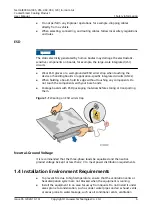
Page 16: ...g materials before storing or transporting them Figure 1 1 Wearing an ESD wrist strap Neutral Ground Voltage It is recommended that the three phase loads be equalized and the neutral ground voltage be kept at less than 2 V to meet power distribution requirements 1 4 Installation Environment Requirements To prevent fire due to high temperature ensure that the ventilation vents or heat dissipation s...

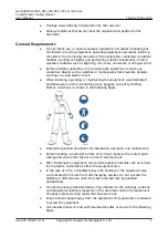
Page 17: ...r personal protective equipment such as the safety helmet and safety belt or waist rope and fasten it to a solid structure Do not mount it on an insecure moveable object or metal object with sharp edges Make sure that the hooks will not slide off Set a restricted area and eye catching signs for working at heights to warn away irrelevant personnel Carry the operation machinery and tools properly to...

Page 18: ...s ladders when you need to perform live working at heights When a step ladder is used ensure that the pull ropes are secured and the ladder is held firm Before using a ladder check that it is intact and confirm its load bearing capacity Do not overload it Ensure that the ladder is securely positioned The recommended angle for a ladder against the floor is 75 degrees as shown in the following figur...

Page 19: ...ide Metal shavings from drilling may short circuit boards inside the equipment Obtain consent from the customer and contractor before drilling holes Wear goggles and protective gloves when drilling holes When drilling holes protect the equipment from shavings After drilling clean up any shavings that have accumulated inside or outside the equipment Moving Heavy Objects DANGER When pulling the equi...

Page 20: ...elding At least two persons are required on a welding site A welder must have a work permit A welding site must be free from inflammables Ensure that a fire extinguisher wet wiper and water container are available A burning welding torch must not be placed on a component or on the floor and must not be placed in a metal container with acetylene and oxygen Otherwise the gas may leak and cause a fir...

Page 21: ...r wastes that have a shell in European Union EU areas To avoid environment pollution and harm to human health wastes must be classified and recycled This also promotes resource reuse When recycling a device fill in the device information in the recycling collection system or contact your dealer for help The dealer can help you recycle devices in a safe and environment friendly way 1 7 Others Exerc...

Page 22: ...l8000 A045U40D4 NetCol8000 A045U4WE4 NetCol8000 A045U40E4 NetCol8000 A055D4WE4 NetCol8000 A060D40E4 NetCol8000 A060D4WE4 NetCol8000 A060U40E4 NetCol8000 A060U4WE4 NetCol8000 A090D4FD4 NetCol8000 A090D40D4 NetCol8000 A090D4FE4 NetCol8000 A090D40E4 NetCol8000 A120D40E4 NetCol8000 A120D4FE4 NetCol8000 A 045 055 060 090 120 In room Air Cooled Smart Cooling Product User Manual 2 Product Description Iss...

Page 23: ...ter and humidifier types 0 none W level 1 electric heater and wet film humidifier F level 2 electric heater and wet film humidifier 8 Packaging type D package for Chinese markets E package for international markets 9 Special identifier for orders 4 no condensate pump dual power supplies 2 1 2 Outdoor Unit Model Number Description This document involves the following product models NetCol500 A060MC...

Page 24: ... model code 110 5 Power supply M 380 415 V three phase 50 Hz 6 Climate type C common non corrosive environment S common harsh environment class C environment 7 Fan type 1 EC fan 8 Packaging type D packaging code D E packaging code E 9 Special identifier for orders 0 none 2 1 3 Water Cooled Module Model Number Description This document involves the following product model NetCol500 W0556C4E0 NetCol...

Page 25: ...ype E packaging code E 9 Special identifier for orders 0 none 2 2 Overview Fans absorb indoor hot air that then moves to the evaporator with heat transmitted to the refrigerant The refrigerant is discharged to the outdoor unit using the compressor releasing heat to the outdoor environment The indoor unit and outdoor condenser are connected and circulate using refrigerant in a sealing manner NetCol...

Page 26: ...ingle system and the NetCol8000 A090 and NetCol8000 A120 is a dual system The outdoor units NetCol500 A060 NetCol500 A080 NetCol500 A110 and NetCol500 W055 water cooled module are single system units The NetCol500 A120 is a dual system unit NetCol8000 A 045 055 060 090 120 In room Air Cooled Smart Cooling Product User Manual 2 Product Description Issue 05 2020 10 10 Copyright Huawei Technologies C...

Page 27: ...devices use the same outdoor unit The following uses a downflow device as an example Figure 2 5 NetCol8000 A090 configuration NetCol8000 A 045 055 060 090 120 In room Air Cooled Smart Cooling Product User Manual 2 Product Description Issue 05 2020 10 10 Copyright Huawei Technologies Co Ltd 17 ...

Page 28: ...the same outdoor unit The following uses a downflow device as an example Figure 2 8 NetCol8000 A120 configuration 2 3 Component Description 2 3 1 Indoor Unit NetCol8000 A 045 055 060 090 120 In room Air Cooled Smart Cooling Product User Manual 2 Product Description Issue 05 2020 10 10 Copyright Huawei Technologies Co Ltd 18 ...

Page 29: ...l 7 Fan 8 Compressor 9 Suction pressure sensor 10 Wet film humidifier optional 11 Oil separator 12 Discharge pressure sensor 13 User wiring terminal 14 Temperature and humidity T H sensor 15 Differential pressure switch 16 Main control module 17 Display module NetCol8000 A 045 055 060 090 120 In room Air Cooled Smart Cooling Product User Manual 2 Product Description Issue 05 2020 10 10 Copyright H...

Page 30: ...essure sensor 9 Compressor 10 Evaporator 11 Discharge pressure sensor 12 User wiring terminal 13 T H sensor 14 Differential pressure switch 15 Main control module 16 Electric control box 17 Display module 18 Electric heater optional NetCol8000 A 045 055 060 090 120 In room Air Cooled Smart Cooling Product User Manual 2 Product Description Issue 05 2020 10 10 Copyright Huawei Technologies Co Ltd 20...

Page 31: ...n 10 Filter dryer 11 Sight glass 12 Suction pressure sensor 13 Oil separator 14 Discharge pressure sensor 15 Wet film humidifier optional 16 User wiring terminal 17 Wet film humidifier 18 Main control module 19 Differential pressure switch NetCol8000 A 045 055 060 090 120 In room Air Cooled Smart Cooling Product User Manual 2 Product Description Issue 05 2020 10 10 Copyright Huawei Technologies Co...

Page 32: ... pressure sensor 10 Display module 11 Oil separator 12 Wet film humidifier optional 13 Discharge pressure sensor 14 User wiring terminal 15 T H sensor 16 Main control module 17 Differential pressure switch 18 Electric control box NetCol8000 A 045 055 060 090 120 In room Air Cooled Smart Cooling Product User Manual 2 Product Description Issue 05 2020 10 10 Copyright Huawei Technologies Co Ltd 22 ...

Page 33: ...lter dryer 10 Compressor 11 Fan 12 Wet film humidifier optional 13 User wiring terminal 14 T H sensor 15 Differential pressure switch 16 Main control module 17 Integrated variable frequency drive 18 Indoor fan drive NetCol8000 A 045 055 060 090 120 In room Air Cooled Smart Cooling Product User Manual 2 Product Description Issue 05 2020 10 10 Copyright Huawei Technologies Co Ltd 23 ...

Page 34: ...Discharge pressure sensor 10 Sight glass 11 Filter dryer 12 Compressor 13 Integrated variable frequency drive 14 User wiring terminal 15 T H sensor 16 Main control module 17 Display module 18 Electric heater optional NetCol8000 A 045 055 060 090 120 In room Air Cooled Smart Cooling Product User Manual 2 Product Description Issue 05 2020 10 10 Copyright Huawei Technologies Co Ltd 24 ...

Page 35: ...t consists of the compressor EC fan evaporator EEV oil separator sight glass filter dryer air filter wet film humidifier optional electric heater optional check valve differential pressure switch differential pressure sensor optional and T H sensor Compressor The NetCol8000 A uses a DC inverter compressor that features compact size light weight a long service life low noise easy installation as we...

Page 36: ...porator is adopted to enhance the heat exchange performance increasing the heat exchange efficiency by more than 10 when compared with a traditional solution EEV The throttling device uses a miniature controller to control the operation of the step motor thereby changing the pass through area of the valve to regulate the flow of refrigerant The EEV is equipped with an energy storage unit that prev...

Page 37: ...ro differential pressure sensor The micro differential pressure sensor adjusts air volume based on the differential pressure to ensure precise air supply No excessive adjustment helps save energy and reduce power consumption The air supply volume is also sufficient which helps eliminate hot spots and improves reliability T H sensor The NetCol8000 A provides built in negative temperature coefficien...

Page 38: ...t buzzing There is an unacknowledged critical alarm Note In the preceding conditions the indicator blinks at a frequency of 1 Hz that is on for 0 5s and off for 0 5s Functions Function Description Single unit control Each unit has an independent control system to ensure normal and high precision operation Operations Users can set parameters and query status on the 7 inch true color touchscreen Net...

Page 39: ... the same equipment room operating in opposite status to save energy Independent teamwork control If a communications cable in the teamwork network is disconnected two teamwork networks are formed A unit in the network without a master unit can automatically become the master unit to continue teamwork control Remote management Users can remotely manage the operating status of one or more units Sto...

Page 40: ...rt fault records in one click mode making it easy to operate the device and know the running status of the device The device supports communications protocols such as Modbus RTU Modbus TCP and SNMP facilitating connection to the network management system The display panel intelligently identifies abnormal parameter settings incorrect commands and rejects them automatically If the indoor temperatur...

Page 41: ...ading communications cables RS485 12V port connects a temperature and humidity T H sensor COM FE port connects a monitoring communications cable Appeara nce Port FE_1 and FE_2 CAN_IN and CAN_OU T RS485 1 2V Port COM FE Port Pin PIN1 FE TX RS485 T RS485 HT FE TX PIN2 FE TX RS485 T RS485 HT FE TX PIN3 FE RX 12V FE RX PIN4 RS485 R RS485 HT RS485 PIN5 RS485 R RS485 HT RS485 PIN6 FE RX FE RX PIN7 CANH ...

Page 42: ...on DP port connects to the display module Appearance DP Port Connects to the display module for communication and power supply Button Exterior SW button When the smart cooling product is shut down and the admin user has logged in if you hold down the button for more than 10s a red frame is added to the button that involves a risky operation on the display module within 5 minutes You can press and ...

Page 43: ...before delivery and the pipe ports are properly sealed to prevent foreign matter from entry 2 3 3 Low Temperature Component Working Principle When the outdoor temperature is below the operating temperature lower limit specified for the product the condensing pressure of the system for the outdoor unit condenser with natural cooling may still be below the safe operating pressure of the compressor A...

Page 44: ...closes The refrigerant at the compressor outlet flows to the liquid storage unit of the low temperature component through the condenser and the system runs properly Appearance Figure 2 19 Low temperature component 1 Safety valve 2 Port for the indoor unit liquid pipe 3 Port for the outdoor unit liquid pipe 4 Condensing pressure regulator valve 5 Differential pressure valve 6 Port for the outdoor u...

Page 45: ...ater for heat exchange to improve the heat exchange efficiency and improve the energy efficiency of the entire system to 4 0 COP 2 4 Physical Ports Table 2 5 Physical ports Item Specifications Indoor unit Refrigerant liquid pipe port Outer diameter of 5 8 inch 15 88 mm welding Refrigerant gas pipe port Outer diameter of 7 8 inch 22 22 mm welding Humidifier water inlet pipe port G 3 4 inch outer sc...

Page 46: ... thread Low temperature component optional component Connecting to the indoor unit liquid pipe Outer diameter of 5 8 inch 15 88 mm welding Connecting to the indoor unit gas pipe Outer diameter of 7 8 inch 22 22 mm welding Connecting to the outdoor unit liquid pipe Outer diameter of 5 8 inch 15 88 mm welding Connecting to the outdoor unit gas pipe Outer diameter of 7 8 inch 22 22 mm welding NetCol8...

Page 47: ... Hz Number of fans 1 1 2 Total cooling capacity kW a 45 45 90 Sensible cooling capacity kW a 45 45 90 Air volume m3 h 11250 11250 22500 Optional Reheating capacity kW a 6 6 12 Optional Humidification capacity kg h a 4 5 4 5 10 NetCol8000 A 045 055 060 090 120 In room Air Cooled Smart Cooling Product User Manual 3 Technical Specifications Issue 05 2020 10 10 Copyright Huawei Technologies Co Ltd 37 ...

Page 48: ... H x W x D mm 2000 x 900 x 900 2000 x 900 x 900 2000 x 1800 x 1000 Air filter level G4 G4 G4 Net weight kg 337 334 5 643 a Tested under rated working conditions indoor dry bulb temperature 35 C relative humidity 26 outdoor temperature 35 C Table 3 2 Technical specifications of NetCol8000 A055 Item NetCol8000 A055D Power supply 380 415 V AC 3 phase 50 Hz 60 Hz Number of fans 1 Total cooling capacit...

Page 49: ...l8000 A120D Power supply 380 415 V AC 3 phase 50 Hz 60 Hz Number of fans 1 1 2 Total cooling capacity kW a 60 60 120 Sensible cooling capacity kW a 60 60 120 Air volume m3 h 15000 14500 30000 Optional Reheating capacity kW a 6 6 12 Optional Humidification capacity kg h a 6 6 10 Maximum operating current A single power supply With heating and humidification 45 Without heating and humidification 41 ...

Page 50: ...umidification Active route 90 Standby route 82 Without heating and humidification Active route 82 Standby route 82 Dimensions H x W x D mm 2000 x 1100 x 1000 2000 x 1100 x 1000 2000 x 2200 x 1000 Air filter level G4 G4 G4 Net weight kg 400 416 764 a Tested under rated working conditions indoor dry bulb temperature 35 C relative humidity 26 outdoor temperature 35 C 3 2 Outdoor Unit Figure 3 1 NetCo...

Page 51: ...00 x 2250 NOTE You can view the outdoor unit BOM number on the equipment barcode The NetCol500 A060 NetCol500 A080 and NetCol500 A120 use long round mounting holes and must be secured by eight M8x80 stainless expansion bolts The NetCol500 A110 use round mounting holes and must be secured by six M8x80 stainless expansion bolts Figure 3 2 NetCol500 A060 A080 A120 hole dimensions mm NetCol8000 A 045 ...

Page 52: ...52273539 00 6 1047 1181 924 1058 NetCol500 A080 52273541 52273541 00 5 1874 2011 924 1058 NetCol500 A120 52273755 00 2 1044 1178 2018 2152 NetCol500 A110 52274570 1076 1035 NetCol8000 A 045 055 060 090 120 In room Air Cooled Smart Cooling Product User Manual 3 Technical Specifications Issue 05 2020 10 10 Copyright Huawei Technologies Co Ltd 42 ...

Page 53: ...oor unit NetCol8000 A045 A090 40 C to 45 C with the indoor unit NetCol8000 A045 A090 and low temperature components are included 5 C to 55 C with the indoor unit NetCol8000 A045 A090 20 C to 45 C with the indoor unit NetCol8000 A055 A060 A120 20 C to 45 C with the indoor unit NetCol8000 A045 A090 40 C to 45 C with the indoor unit NetCol8000 A045 A090 and low temperature components are included 5 C...

Page 54: ...ntrolled or general outdoor environments with simple shielding measures where the humidity reaches 100 occasionally Class C harsh environment sea environments or outdoor land environments or environments with simple shielding measures which are within 3 7 km away from the sea or within 1 2 km away from a pollution source Class D marine environment environments within 500 m away from the coast The ...

Page 55: ... Net weight 28 kg 3 4 Water Cooled Module Figure 3 5 NetCol500 W dimensions Figure 3 6 NetCol500 W hole dimensions Table 3 5 Operating environment specifications of the water cooled module Item Technical Specifications Power supply 220 240 V AC 1 Ph N PE 50 Hz 60 Hz Refrigerant R410A Heat exchanging capacity 55 kW NetCol8000 A 045 055 060 090 120 In room Air Cooled Smart Cooling Product User Manua...

Page 56: ...ude 0 4000 m derated at 1000 m or above Environment type Enclosed indoor environment in which the temperature and humidity can be controlled within the ranges of 4 C to 45 C and 5 RH to 90 RH respectively If the indoor installation position is ventilated it should be more than 3 7 km away from the sea or pollution sources such as salt lakes chemical plants mineral plants thermal power plants and c...

Page 57: ... RH Temperature adjustment precision 1 C Humidity adjustment precision 5 RH Indoor operating temperature 18 40 C Operating humidity 20 80 RH Storage temperature 40 C to 70 C Storage humidity 5 95 RH non condensing Air outlet static pressure 0 300 Pa adjustable NetCol8000 A 045 055 060 090 120 In room Air Cooled Smart Cooling Product User Manual 3 Technical Specifications Issue 05 2020 10 10 Copyri...

Page 58: ... 45 C If a low temperature component is used the lowest temperature is 40 C Two NetCol8000 A045 units work with one NetCol500 A120 20 C to 45 C If a low temperature component is used the lowest temperature is 40 C One NetCol8000 A090 works with one NetCol500 A120 20 C to 45 C If a low temperature component is used the lowest temperature is 40 C One NetCol8000 A055 works with one NetCol500 A110 5 C...

Page 59: ...e actual total load of servers corresponding to a single smart cooling product is less than 10 of the cooling capacity of the smart cooling product or the equipment room is not properly sealed the humidity in the equipment room may be too high This is not a product quality issue and should be dealt with by adding a dehumidifier Table 3 8 Installation requirements Item Specifications Equipm ent roo...

Page 60: ...of the NetCol8000 A045 55 90 is greater than or equal to 900 mm In special cases the maintenance distance after the door is removed is greater than or equal to 800 mm The maintenance distance from the front of the NetCol8000 A060 120 is greater than or equal to 1100 mm In special cases the maintenance distance after the door is removed is greater than or equal to 800 mm Power Leakage circuit break...

Page 61: ... should be higher than the top copper pipe of the condenser If the outdoor unit is lower than the indoor unit The vertical height difference between the indoor and outdoor units should not exceed 8 m When calculating the height difference use the bottom of the compressor as the reference for the indoor unit and the bottom of the condenser as the reference for the outdoor unit In the figure is a si...

Page 62: ...bottom of the outdoor unit If the outdoor unit is lower than the indoor unit The vertical height difference between the indoor and outdoor units should not exceed 8 m When calculating the height difference use the bottom of the compressor as the reference for the indoor unit and the bottom of the condenser as the reference for the outdoor unit The equivalent length of the one way pipe should be eq...

Page 63: ...of the NetCol8000 A by using a baffle or plastic bag to prevent dust entering Layout Requirements Install the unit in a spacious space Check whether the environment meets the requirements before installation and whether reconstruction is required for routing water pipes and cables and constructing ventilation pipes The equipment room should have good heat insulation and the walls and floor should ...

Page 64: ...ipes or cables Properly determine the positions for routing pipes and cables to avoid interference The height of raised floors is greater than 300 mm for upflow units W indicates the distance between smart cooling products The minimum distance is 300 mm for upflow units or 500 mm for downflow units L indicates the front maintenance distance for the device The minimum distance is 900 mm for the Net...

Page 65: ...ow units is greater than 300 mm L indicates the front maintenance distance for the device The minimum maintenance distance is 900 mm for the NetCol8000 A045 NetCol8000 A055 and NetCol8000 A090 or 1100 mm for the NetCol8000 A060 and NetCol8000 A120 If the front distance cannot meet the requirements remove the front door for maintenance The minimum distance is 800 mm Figure 4 5 Layout of side pipe r...

Page 66: ...ly flows into and out of the condenser Install an outdoor unit in clean areas that are away from residential areas Take thermal insulation measures for pipes connecting indoor and outdoor units Do not use the copper pipe or electric control box as a weight bearing point when moving the outdoor unit and keep the fins intact When routing pipes for the condenser ensure that the pipes are routed in fr...

Page 67: ...pport vertical installation Figure 4 9 shows the horizontal installation Figure 4 17 shows the compact outdoor unit installation requirement The outdoor unit should be installed against a wall if possible when it is installed vertically If the site does not meet the requirements and the local outdoor temperature is lower than 5 C add an air baffle The height and width of the air baffle must be gre...

Page 68: ...orizontal installation for NetCol500 A110 unit mm Figure 4 10 Top view of vertical installation space for the NetCol500 A080 without an air baffle unit mm NetCol8000 A 045 055 060 090 120 In room Air Cooled Smart Cooling Product User Manual 4 System Installation Issue 05 2020 10 10 Copyright Huawei Technologies Co Ltd 58 ...

Page 69: ...and the low temperature component must be placed at the same height of base or concrete platform When an outdoor unit is installed vertically the outdoor unit must not be lower than the low temperature component and the height difference cannot exceed 1 5 m Compact installation scenario NOTE If the space does not meet the requirements of the recommended layout you can use any of the following layo...

Page 70: ... height is 0 mm the base height is 0 mm If the wall height is 1000 mm or lower the base height is 500 mm or higher When the quantity is more than 12 if the wall height is 0 mm the base height is 500 mm or higher If the wall height is 1000 mm or lower the base height is 1000 mm or higher Figure 4 15 Top view of compact installation if the quantity is 6 NetCol500 A120 NetCol8000 A 045 055 060 090 12...

Page 71: ...anner The base height is greater than or equal to 500 mm and the wall height is less than or equal to 1000 mm 4 1 5 Installation Requirements for the Water Cooled Module Installation environment Enclosed indoor environment in which the temperature and humidity can be controlled within the ranges of 4 C to 45 C and 5 RH to 90 RH respectively If the indoor installation position is ventilated it shou...

Page 72: ...in the following figure Figure 4 18 Stacking scenario 1 Water strainer The water cooled module should be installed on a concrete base The base requirements are as follows Figure 4 19 Concrete base dimensions unit mm 1 Mounting hole 4 x M12 The following figure shows the operation area requirements for water cooled modules NetCol8000 A 045 055 060 090 120 In room Air Cooled Smart Cooling Product Us...

Page 73: ...e site requirements Category Tool Personal protective equipment PPE Safety gloves Safety goggles Anti dust mask Safety shoes Safety helmet Safety belt Transportation Manual pallet truck Electric pallet truck Hoisting rope bearing capacity 400 kg Lever bearing capacity 400 kg General Measuring tape Right angle Marker Hammer drill NetCol8000 A 045 055 060 090 120 In room Air Cooled Smart Cooling Pro...

Page 74: ... M3 M4 Electric screwdriver Diagonal pliers Needle nose pliers Combination pliers Hacksaw Step ladder 2 m Flashlight Thermometer Pipe Cutter Thread sealant or sealing tape a Thermal insulation foam sealant or sealing tapeb Welding torch NetCol8000 A 045 055 060 090 120 In room Air Cooled Smart Cooling Product User Manual 4 System Installation Issue 05 2020 10 10 Copyright Huawei Technologies Co Lt...

Page 75: ...ressure resistance above 1 6 MPa Compliant with industry standards b Temperature resistance 85 C at least for thermal insulation foam sealant or sealing tape Cable Wire strippers Power cable crimping tool Insulation tape Heat shrink tubing Heat gun Cable tie Commissioning Vacuum pumpc Rubber hose 5 PCS d Pressure gauge 2 PCS d Reducing valvee NetCol8000 A 045 055 060 090 120 In room Air Cooled Sma...

Page 76: ...gerant leakage during the removal of a rubber hose which may cause frostbite e The nitrogen cylinder port should have a reducing valve and the measuring range should be at least 4 0 MPa f Dry nitrogen 4 2 2 Materials Item Description Type Standard material This type of materials is provided by Huawei and you can find them in the fittings delivered with the equipment Materials in the packing list A...

Page 77: ...rigerant cylinder outer surface and connect a pressure gauge to the pressure tank to measure the internal pressure Find the saturation pressure corresponding to the measured external surface temperature from the mapping table If the deviation between the saturation pressure and the measured internal pressure is greater than 0 2 MPa the refrigerant does not meet the requirements and needs to be rep...

Page 78: ...r purchase it by yourself after being confirmed by the supplier NOTE Add refrigerant oil only if it leaks Contact the supplier to confirm the amount of refrigerant oil to be added 4 2 2 3 Refrigerant Pipe Components Liquid pipe L 60 m R410A copper pipe outer diameter of 5 8 inch 15 88 mm wall thickness of 1 0 mm operating pressure 4 5 MPa 60 m L 100 m R410A copper pipe outer diameter of 3 4 inch 1...

Page 79: ...aps No Name Outer Diameter and Thickness mm Technical Requirements 1 Oil trap 22 2x1 2 Inner diameter at the expanded end of the copper pipe 22 4 mm outer diameter at the shrunk end 19 5 mm 2 Oil trap 25 4x1 2 Inner diameter at the expanded end of the copper pipe 25 8 mm outer diameter at the shrunk end 22 6 mm 3 Inverted trap of gas pipes 22 2x1 2 Inner diameters at the two expanded ends of the c...

Page 80: ...G 3 4 inch 2 Adapter with inner screw threads G 3 4 inch Plastic materials such as PA66 and metal materials are recommended 3 Matched with the adapter the pressure resistance should be at least 0 7 MPa NOTE The object shown in the dotted line box is the water inlet pipe connector with outer screw threads delivered with smart cooling products Other parts are not provided and need to be purchased 4 ...

Page 81: ... inner screw threads delivered with smart cooling products The hose clamp as shown by 5 in the preceding figure is provided in standard configuration Other parts are not provided and need to be purchased 4 2 2 6 Water Inlet and Outlet Pipes for the Water Cooled Module Figure 4 25 Water pipe connection diagram 1 Internal thread connector G1 1 2 inch internal thread connector delivered with the smar...

Page 82: ...repare two groups of outdoor unit cables When the NetCol8000 A090 120 indoor unit is used prepare two groups of outdoor unit cables for each indoor unit Shielded cables cannot be used as power cables for outdoor units The signal cable is a shielded cable and the shield layer must be reliably grounded Otherwise device communication is affected The cable diameter must comply with local cable standar...

Page 83: ...mm2 5 x 10 mm2 4 x 25 mm2 4 x 25 mm2 PE 16 mm2 16 mm2 Standby power cable for the indoor unit Maximum current 36 A 41 A 72 A 82 A Recommend ed upstream circuit breaker 50 A 3P characteri stics of C 63 A 3P characteri stics of C 100 A 3P character istics of C 125 A 3P character istics of C Rec om me nde d cab le L1 L2 L3 N 5 x 10 mm2 5 x 10 mm2 4 x 25 mm2 4 x 25 mm2 PE 16 mm2 16 mm2 Outdoor unit po...

Page 84: ...r e control monitoring board Recommend ed cable 3 x 1 5 mm2 shielded outdoor cable 3 x 1 5 mm2 shielded outdoor cable 3 x 1 5 mm2 shielded outdoor cable 3 x 1 5 mm2 shielded outdoor cable Teamwork control network cable mandatory for teamwork networking Recommend ed cable 8 pin standard network cable 8 pin standard network cable 8 pin standard network cable 8 pin standard network cable NetCol8000 A...

Page 85: ...etween cables is greater than twice the cable diameter The AC voltage loss is less than 3 Single or multi core 90 C resistant copper flexible cables are used Table 4 4 Power cable terminal requirements Item NetCol8000 A045 A055 A060 A090 A120 Terminal L1 L2 L3 N PE Connection mode Cord end terminal OT terminal Torque 2 0 N m 4 5 N m 4 3 Unpacking and Checking Prerequisites Move the smart cooling p...

Page 86: ...or Unit 4 4 1 Checking the Indoor Unit Pressure Procedure Step 1 Open the front door Step 2 Remove the fan maintenance plate Step 3 Take out the desiccant bag Step 4 Check whether any of the needle valve bonnets shown in Figure 4 27 is missing by turns 1 If they do not exist contact Huawei technical support 2 If they exist remove each valve bonnet and use it to press the valve plugs in turn If nit...

Page 87: ...quid pipe needle valve Figure 4 28 Positions of the NetCol8000 A045 needle valves upflow 1 Exhaust pipe needle valve 2 Low pressure needle valve 3 Liquid pipe needle valve NetCol8000 A 045 055 060 090 120 In room Air Cooled Smart Cooling Product User Manual 4 System Installation Issue 05 2020 10 10 Copyright Huawei Technologies Co Ltd 77 ...

Page 88: ...he NetCol8000 A060 needle valves upflow 1 Exhaust pipe needle valve 2 Low pressure needle valve 3 Liquid pipe needle valve End 4 4 2 Removing the Transport Fixing Sheet Metals 4 4 2 1 Removing the Indoor Unit Pallet NetCol8000 A 045 055 060 090 120 In room Air Cooled Smart Cooling Product User Manual 4 System Installation Issue 05 2020 10 10 Copyright Huawei Technologies Co Ltd 78 ...

Page 89: ... 2 2 Removing the Transport Fasteners from the Compressor Procedure Step 1 Loosen the three bolts on the compressor transport fasteners using a 13 solid wrench Figure 4 32 Removing the transport fasteners from the compressor NetCol8000 A 045 055 060 090 120 In room Air Cooled Smart Cooling Product User Manual 4 System Installation Issue 05 2020 10 10 Copyright Huawei Technologies Co Ltd 79 ...

Page 90: ... cabinet onto the base and align the cabinet mounting holes with the base mounting holes Step 3 Secure the cabinet using the M12 bolts in the fittings bag Figure 4 33 Securing the cabinet End 4 5 Installing an Outdoor Unit 4 5 1 Checking the Outdoor Unit Pressure Context Before delivery outdoor units are injected with nitrogen to 0 2 0 6 MPa Before connecting pipes the nitrogen inside pipes must b...

Page 91: ...4 34 or Figure 4 35 Figure 4 34 Checking the outdoor unit pressure for NetCol500 A060 Figure 4 35 Checking the outdoor unit pressure NetCol500 A110 If the pressure gauge reading is no less than 0 2 MPa the unit is airtight Then open the pressure gauge valve where the hose is connected to discharge nitrogen After the discharge is complete remove the hose and reinstall the valve bonnet NetCol8000 A ...

Page 92: ... balance To prevent shocks or falls move the cabinet gently After placing the cabinet in the installation position unpack it and take care to prevent scratches Keep the cabinet steady during unpacking Procedure Step 1 Remove the packing materials such as the carton stretch wrap foam condenser protection cardboard and plastic bags Step 2 Check the accessories against the accessory list Step 3 Remov...

Page 93: ...ighten the six stainless steel bolts for each support leg and the two stainless steel fastening bolts that secure each support leg to the ground Procedure Step 1 Remove the four corner fittings from the side panels of the outdoor unit by removing two M6x16 stainless steel bolts from each corner fitting NetCol8000 A 045 055 060 090 120 In room Air Cooled Smart Cooling Product User Manual 4 System I...

Page 94: ...ling legs Step 3 Put the four legs to the ground to lay the outdoor unit horizontally NOTICE When turning the outdoor unit do not hold it by using two legs Otherwise the outdoor unit is damaged NetCol8000 A 045 055 060 090 120 In room Air Cooled Smart Cooling Product User Manual 4 System Installation Issue 05 2020 10 10 Copyright Huawei Technologies Co Ltd 84 ...

Page 95: ... or concrete platform End 4 5 3 3 Vertical Installation Scenario NetCol500 A060 NetCol500 A080 When the outdoor unit is vertically installed it can be directly secured to the ground or installed on a base The NetCol500 A080 is used as an example For details about NetCol500 A060 operations refer to this section Securing an Outdoor Unit to the Ground Step 1 Secure an outdoor unit to the ground throu...

Page 96: ...e first layer base to the ground using six M12x60 stainless steel expansion anchor bolts Figure 4 41 Securing a base NOTE Only four bolts are required to secure the NetCol500 A060 double layer base to the ground Step 2 Secure the four columns NetCol8000 A 045 055 060 090 120 In room Air Cooled Smart Cooling Product User Manual 4 System Installation Issue 05 2020 10 10 Copyright Huawei Technologies...

Page 97: ...e middles of the four columns using twelve M10x30 stainless steel bolts as shown by 2 in Figure 4 42 Step 3 Secure an outdoor unit onto the first layer base Figure 4 43 Securing an outdoor unit onto the first layer base NetCol8000 A 045 055 060 090 120 In room Air Cooled Smart Cooling Product User Manual 4 System Installation Issue 05 2020 10 10 Copyright Huawei Technologies Co Ltd 87 ...

Page 98: ...on the outdoor unit side as shown in Figure 4 43 Step 4 Secure four slanting beams to the base using eight M10x30 stainless steel bolts as shown in Figure 4 44 Figure 4 44 Installing slanting beams Step 5 Secure the three beams on the top to the base using six M10x30 stainless steel bolts as shown in Figure 4 45 NetCol8000 A 045 055 060 090 120 In room Air Cooled Smart Cooling Product User Manual ...

Page 99: ...ms Step 6 Secure an outdoor unit onto the second layer base NetCol8000 A 045 055 060 090 120 In room Air Cooled Smart Cooling Product User Manual 4 System Installation Issue 05 2020 10 10 Copyright Huawei Technologies Co Ltd 89 ...

Page 100: ...n the base side and two M6x16 stainless steel bolts are used on the outdoor unit side as shown in Figure 4 46 3 Secure the last beam on the top to the base using two M10x30 stainless steel bolts as shown by 4 in Figure 4 46 End 4 5 3 4 Vertical Installation NetCol500 A120 Step 1 Secure the bottom of the outdoor unit NetCol8000 A 045 055 060 090 120 In room Air Cooled Smart Cooling Product User Man...

Page 101: ...m of the outdoor unit Step 2 Secure the top of the outdoor unit NetCol8000 A 045 055 060 090 120 In room Air Cooled Smart Cooling Product User Manual 4 System Installation Issue 05 2020 10 10 Copyright Huawei Technologies Co Ltd 91 ...

Page 102: ... not exist contact Huawei technical support If they exist remove each valve bonnet and use it to press the valve plugs in turn If nitrogen is exhausted the system is working properly If no nitrogen is exhausted contact Huawei technical support NetCol8000 A 045 055 060 090 120 In room Air Cooled Smart Cooling Product User Manual 4 System Installation Issue 05 2020 10 10 Copyright Huawei Technologie...

Page 103: ...olts from the bracket angles connecting the water cooling module and the pallet and then remove the outdoor unit from the pallet as shown in following figure Figure 4 49 Removing the pallet Step 2 Remove the water cooling module from the pallet End 4 6 3 Securing a Water Cooling Module Place the water cooling module on a concrete base and align the mounting holes with the holes in the concrete bas...

Page 104: ...ets of all needle valves If a bonnet is missing contact technical support Step 2 Connect the rubber hose to the pressure gauge and tighten all pressure gauge valves Step 3 Remove the bonnet from the needle valve store it properly and connect the other end of the rubber hose to the needle valve NetCol8000 A 045 055 060 090 120 In room Air Cooled Smart Cooling Product User Manual 4 System Installati...

Page 105: ...support Figure 4 52 Checking the nitrogen pressure End 4 7 2 Removing Transport Fasteners Step 1 Remove the screws from the pallet and move the device off the pallet Figure 4 53 Removing the screws from the pallet End 4 7 3 Securing the Low Temperature Component Step 1 Secure the device to the base NetCol8000 A 045 055 060 090 120 In room Air Cooled Smart Cooling Product User Manual 4 System Insta...

Page 106: ...n 9 2 mm When purchasing water pipes ensure that the water pipe with thermal insulation foam warped can go through the ports on the bottom and top boards 4 8 1 Notices for Laying Pipes NetCol8000 A 045 055 060 090 120 In room Air Cooled Smart Cooling Product User Manual 4 System Installation Issue 05 2020 10 10 Copyright Huawei Technologies Co Ltd 96 ...

Page 107: ... outdoor units is the shortest When selecting the refrigerant pipes note the following 1 Avoid bends and ensure that the connection between indoor and outdoor units is the shortest 2 After determining the best pipe route between the indoor and outdoor units calculate the number of the components that cause local resistance loss for example elbows and convert them into the equivalent length to stra...

Page 108: ...quired by Figure 4 55 When the direction of the refrigerant pipe is changed add a support at the position that is 500 mm away from the changing point In a straight section of the refrigerant pipe add a support every 1500 mm Figure 4 55 Refrigerant pipe installation diagram NOTE Onsite personnel are responsible for preparing the required materials and installing the supports NetCol8000 A 045 055 06...

Page 109: ...pes can be routed from the bottom or side Select the pipe routing based on the actual situation Exhausting Nitrogen DANGER Before welding refrigerant pipes fully exhaust nitrogen from the refrigerant pipes to avoid explosion and injuries Step 1 Remove the bonnet of the low pressure needle valve shown in Figure 4 56 and connect the pressure gauge leather hose to the needle valve NetCol8000 A 045 05...

Page 110: ...ted remove the pressure gauge and install the valve bonnet Step 4 Continue exhausting nitrogen from the exhaust pipe needle valve and liquid pipe needle valve by performing Step 1 Step 3 End Bottom Pipe Routing Step 1 Remove the plugs from the bottom refrigerant pipe using a welding torque NetCol8000 A 045 055 060 090 120 In room Air Cooled Smart Cooling Product User Manual 4 System Installation I...

Page 111: ...Liquid pipe 2 Gas pipe Figure 4 58 NetCol8000 A045 bottom pipe routing upflow 1 Gas pipe 2 Liquid pipe NetCol8000 A 045 055 060 090 120 In room Air Cooled Smart Cooling Product User Manual 4 System Installation Issue 05 2020 10 10 Copyright Huawei Technologies Co Ltd 101 ...

Page 112: ...uid pipe 2 Gas pipe Figure 4 60 NetCol8000 A060 bottom pipe routing upflow 1 Gas pipe 2 Liquid pipe NetCol8000 A 045 055 060 090 120 In room Air Cooled Smart Cooling Product User Manual 4 System Installation Issue 05 2020 10 10 Copyright Huawei Technologies Co Ltd 102 ...

Page 113: ...ugh the liquid pipe needle valve Figure 4 61 Welding pipes Step 2 Applicable to downflow units Cut a cross in the rubber ring using a utility knife and route the pipe wrapped with the thermal insulation foam through the hole NOTICE Ensure that the rubber ring is not disconnected If the rubber ring is disconnected or damaged seal the gaps around the pipes with mastic cement or thermal insulation fo...

Page 114: ...Liquid pipe 2 Gas pipe Figure 4 63 NetCol8000 A045 side pipe routing upflow 1 Gas pipe 2 Liquid pipe NetCol8000 A 045 055 060 090 120 In room Air Cooled Smart Cooling Product User Manual 4 System Installation Issue 05 2020 10 10 Copyright Huawei Technologies Co Ltd 104 ...

Page 115: ...0 A120 side pipe routing downflow 1 Liquid pipe 2 Gas pipe NetCol8000 A 045 055 060 090 120 In room Air Cooled Smart Cooling Product User Manual 4 System Installation Issue 05 2020 10 10 Copyright Huawei Technologies Co Ltd 105 ...

Page 116: ... then fill nitrogen at 0 03 0 05 MPa into the copper pipe to avoid internal oxidation as shown in Figure 4 61 When welding a gas pipe gently inject nitrogen into the pipe through the exhaust pipe needle valve When welding a liquid pipe gently inject nitrogen into the pipe through the liquid pipe needle valve Step 2 Cut a cross in the rubber ring using a utility knife and route the pipe wrapped wit...

Page 117: ...ant pipes fully exhaust nitrogen from the refrigerant pipes to avoid explosion and injuries 2 When you welding pipes pay attention to protecting surrounding components and cables Step 1 Remove the plugs using a welding torque Step 2 Connect the gas and liquid pipes to the gas and liquid pipes of the indoor unit respectively Step 3 Wrap the thermal insulation foam Figure 4 66 Welding outdoor unit p...

Page 118: ...he outdoor unit Figure 4 68 and Figure 4 69 show the related inlet and outlet pipe ports Install an inverted trap respectively at the inlet and outlet pipe ports on the outdoor unit condenser preventing refrigerant from returning Figure 4 68 Ports on the low temperature component 1 Connecting to the indoor unit liquid pipe 5 8 inch 15 88 mm 2 Connecting to the outdoor unit liquid pipe 5 8 inch 15 ...

Page 119: ...e the plugs at the refrigerant pipe ends 2 Connect the gas and liquid pipes to the gas and liquid pipes of the indoor unit respectively NOTE Take protective measures such as spreading a piece of wet cloth around the welding position to avoid burning the needle valves pipe plugs of other end thermal insulation foam cables and labels Figure 4 70 Welding refrigerant pipes for the water cooling module...

Page 120: ...eads Figure 4 71 Connecting water pipes End 4 8 7 Optional Connecting the Humidifier Water Inlet Pipe Context A reducing valve must be installed if the inlet water pressure exceeds 0 7 MPa Appliance is intended to be permanently connected to the water mains and not connected by a hose set Procedure Step 1 Install the adapter of the humidifier inlet water pipe Sealing washer is recommended NetCol80...

Page 121: ...ngineering pipes before connecting the water inlet pipe to the engineer pipe to avoid impurities entering into the humidifier Step 5 Connect the water inlet pipe to the engineer pipe and wrap the pipe with thermal insulation foam End 4 8 8 Connecting the Drainpipe Context The following uses hose bottom routing as an example to describe how to connect drainpipes Bottom Pipe Routing Step 1 Install t...

Page 122: ... pipe routing downflow Figure 4 74 NetCol8000 A045 bottom pipe routing upflow NetCol8000 A 045 055 060 090 120 In room Air Cooled Smart Cooling Product User Manual 4 System Installation Issue 05 2020 10 10 Copyright Huawei Technologies Co Ltd 112 ...

Page 123: ...pplicable to downflow units Cut a cross in the rubber ring using a utility knife and route the pipe wrapped with the thermal insulation tube through the hole NetCol8000 A 045 055 060 090 120 In room Air Cooled Smart Cooling Product User Manual 4 System Installation Issue 05 2020 10 10 Copyright Huawei Technologies Co Ltd 113 ...

Page 124: ... CAUTION The entire drainpipe should be closely wrapped with thermal insulation foam thickness of 3 mm is recommended The drainpipe should be less than or equal to 3 m long with a certain gradient 1 100 or larger is recommended No upward or wavy bend is allowed as shown in the following figure Figure 4 77 Drainpipe installation specifications End NetCol8000 A 045 055 060 090 120 In room Air Cooled...

Page 125: ...n charging nitrogen to retain the pressure to prevent the nitrogen from leaking Procedure Step 1 Connect a leather hose pressure gauge reducing valve and nitrogen cylinder to the equipment Ensure that the pressure gauge and reducing valve are closed If no low temperature component is installed on the outdoor side connect pipes as shown in Figure 4 78 and charge nitrogen into the system from the lo...

Page 126: ...gauge 5 Low pressure needle valve 6 Exhaust pipe needle valve Figure 4 79 NetCol8000 A045 charging nitrogen to pipes without configuring low temperature component upflow 1 Nitrogen cylinder 2 Reducing valve 3 Low pressure gauge NetCol8000 A 045 055 060 090 120 In room Air Cooled Smart Cooling Product User Manual 4 System Installation Issue 05 2020 10 10 Copyright Huawei Technologies Co Ltd 116 ...

Page 127: ...uring low temperature component upflow 1 Nitrogen cylinder 2 Reducing valve 3 Low pressure gauge 4 High pressure gauge 5 Low pressure needle valve 6 Exhaust pipe needle valve If a low temperature component is installed on the outdoor side connect pipes as shown in Figure 4 82 Figure 4 83 Figure 4 84 or Figure 4 85 and charge nitrogen into the system from the low pressure exhaust pipe and liquid pi...

Page 128: ...n cylinder 2 Reducing valve 3 Pressure gauge 1 4 Pressure gauge 2 5 Low pressure needle valve 6 Exhaust pipe needle valve 7 Liquid pipe needle valve NetCol8000 A 045 055 060 090 120 In room Air Cooled Smart Cooling Product User Manual 4 System Installation Issue 05 2020 10 10 Copyright Huawei Technologies Co Ltd 118 ...

Page 129: ...needle valve Figure 4 84 NetCol8000 A060 A120 charging nitrogen to pipes with a low temperature component downflow 1 Nitrogen cylinder 2 Reducing valve 3 Pressure gauge 1 4 Pressure gauge 2 5 Low pressure needle valve 6 Exhaust pipe needle valve 7 Liquid pipe needle valve NetCol8000 A 045 055 060 090 120 In room Air Cooled Smart Cooling Product User Manual 4 System Installation Issue 05 2020 10 10...

Page 130: ...ervation test again NOTICE The outlet pressure must be no more than 3 0 MPa If the outlet pressure is more than 3 0 MPa some parts of the system may be damaged Step 3 If the pressure decreases find out and repair the leakage point by using soap water or a halogen leak detector If the pressure is preserved properly exhaust nitrogen from the three needle valves NOTE For scenarios where equipment is ...

Page 131: ...together Step 4 Adjust the air exhausting speed until no bubble flows out of the needle valve Step 5 Tighten the cooling water side needle valve Step 6 Inject water to 0 8 MPa and preserve the pressure for 24 hours Then connect a pressure gauge to a needle valve on the pipeline to measure the pressure If the reading remains unchanged the pipe is not leaking You can perform the following operations...

Page 132: ...cal regulations Cables must be routed in through cable clips The figure shows cable connections of two power supplies If there is only one power supply you only need to connect cables to QF1 Shielded cables cannot be used as power cables for outdoor units Connecting the Power Cable to an Indoor Unit Step 1 Connect the PE cable to the cabinet ground bar Step 2 Route the external power cable through...

Page 133: ...or the NetCol8000 A045 A055 A090 with dual power supplies downflow NetCol8000 A 045 055 060 090 120 In room Air Cooled Smart Cooling Product User Manual 4 System Installation Issue 05 2020 10 10 Copyright Huawei Technologies Co Ltd 123 ...

Page 134: ...bles for the NetCol8000 A045 with dual power supplies upflow NetCol8000 A 045 055 060 090 120 In room Air Cooled Smart Cooling Product User Manual 4 System Installation Issue 05 2020 10 10 Copyright Huawei Technologies Co Ltd 124 ...

Page 135: ...bles for the NetCol8000 A060 with dual power supplies upflow NetCol8000 A 045 055 060 090 120 In room Air Cooled Smart Cooling Product User Manual 4 System Installation Issue 05 2020 10 10 Copyright Huawei Technologies Co Ltd 125 ...

Page 136: ...er cable to the U V W PE bar of the NetCol500 A air cooled outdoor unit and the other end to the U V W PE port on the indoor unit wiring terminal Connect one end of the power cable for the NetCol500 W water cooled module to the L N terminal on the water cooled module and the other end to the L N terminal on the indoor unit NetCol8000 A 045 055 060 090 120 In room Air Cooled Smart Cooling Product U...

Page 137: ...A060 as examples Figure 4 93 Connecting the power cable to an air cooled outdoor unit 2 using indoor unit NetCol8000 A060U and outdoor unit NetCol500 A110 as examples NetCol8000 A 045 055 060 090 120 In room Air Cooled Smart Cooling Product User Manual 4 System Installation Issue 05 2020 10 10 Copyright Huawei Technologies Co Ltd 127 ...

Page 138: ...nit D Power Cable Filter for an Outdoor Unit lists the recommended filter specifications End Optional Connecting the Power Cable for a Low Temperature Component Step 1 Connect the cable delivered with the low temperature component to the L N terminal on the QF2 of the outdoor unit NetCol8000 A 045 055 060 090 120 In room Air Cooled Smart Cooling Product User Manual 4 System Installation Issue 05 2...

Page 139: ...e indoor unit Step 3 Secure the cables on the post of the cabinet with cable ties End 4 11 3 Connecting Signal Cables NOTICE Before connecting signal cables take effective electrostatic discharge ESD measures The power cables and signal cables should be tied and cased separately The shield layer of signal cable must be grounded 4 11 3 1 Connecting the Signal Cable Between the Outdoor Unit and Indo...

Page 140: ...nd indoor unit The shield layer must be reliably connected to the nearby PE point Figure 4 96 Connecting the signal cable between the air cooled indoor and outdoor units using indoor unit NetCol8000 A060U and outdoor unit NetCol500 A080 as examples A Core wire B Insulation layer C Shield layer D Jacket NetCol8000 A 045 055 060 090 120 In room Air Cooled Smart Cooling Product User Manual 4 System I...

Page 141: ... unit The shield layer of the signal cable must be grounded 4 11 3 2 Connecting Water Sensor Cables Context A water sensor monitors resistance changes at terminals to determine whether the floor is watery When the terminals of a water sensor detect water or other conductive liquid resistance between the two terminals decreases Keep water sensors far away from water traps or floor drains Procedure ...

Page 142: ...water sensor upwards and its detection board downwards on the ground Figure 4 98 Connecting a cable to the water sensor 1 for NetCol8000 A045D NetCol8000 A 045 055 060 090 120 In room Air Cooled Smart Cooling Product User Manual 4 System Installation Issue 05 2020 10 10 Copyright Huawei Technologies Co Ltd 132 ...

Page 143: ...If a micro differential pressure sensor is configured perform the following steps to install it Procedure Step 1 Secure the differential pressure sensor inside the cabinet using two M3 screws NetCol8000 A 045 055 060 090 120 In room Air Cooled Smart Cooling Product User Manual 4 System Installation Issue 05 2020 10 10 Copyright Huawei Technologies Co Ltd 133 ...

Page 144: ...045 A055 A090 downflow Figure 4 101 Installing a micro differential pressure sensor for the NetCol8000 A045 upflow NetCol8000 A 045 055 060 090 120 In room Air Cooled Smart Cooling Product User Manual 4 System Installation Issue 05 2020 10 10 Copyright Huawei Technologies Co Ltd 134 ...

Page 145: ...acent to the pressure inlet The distance between the binding point closer to the pressure inlet and the pressure inlet should not exceed 25 mm and the distance between two binding points is within 20 30 mm Step 3 Connect the cables of the differential pressure sensor to the 4 5 and 6 of x502 terminal Step 4 After powering on the NetCol8000 choose Settings System Settings Indoor Fan and set Air sid...

Page 146: ...t and the T H sensor inside the cabinet in series Figure 4 104 Cables routed outside a cabinet 1 T H sensor outside a cabinet NOTE The T H sensors inside the cabinet are secured at the return air side and their IN ports are connected to the main control board When connecting the T H sensors outside the cabinet connect the OUT port of one T H sensor inside the cabinet to the IN port of the next T H...

Page 147: ...FF Cold aisle 3 temp humid 13 ON OFF ON ON OFF OFF Cold aisle 4 temp humid 14 OFF ON ON ON OFF OFF Cold aisle 5 temp humid 15 ON ON ON ON OFF OFF Hot aisle Hot aisle 1 temp humid 21 ON OFF ON OFF ON OFF Hot aisle 2 temp humid 22 OFF ON ON OFF ON OFF Hot aisle 3 temp humid 23 ON ON ON OFF ON OFF Hot aisle 4 temp humid 24 OFF OFF OFF ON ON OFF NetCol8000 A 045 055 060 090 120 In room Air Cooled Smar...

Page 148: ...e networking scenario The teamwork communications cable must be a shielded network cable of Cat 5e or higher specifications The network cable length between adjacent units must be less than or equal to 100 m and the maximum distance for CAN teamwork communication must be less than or equal to 310 m Route cables in compliance with local standards Take appropriate shielding measures such as using a ...

Page 149: ... RS485 monitoring communications cable 4 Blue 5 White and blue End 4 11 4 2 CAN Teamwork RS485 Monitoring Step 1 Connect teamwork and monitoring communications cables Networking CAN Teamwork RS485 Monitoring Protocol CAN Modbus RTU NetCol8000 A 045 055 060 090 120 In room Air Cooled Smart Cooling Product User Manual 4 System Installation Issue 05 2020 10 10 Copyright Huawei Technologies Co Ltd 139...

Page 150: ...g to Enable on the Modbus Settings screen for each unit If units are grouped n 1 recommended n 4 set RS485 monitoring grouping to Enable on the Modbus Settings screen for the unit with the COM FE port connected Retain the default setting Disable for other units NOTE Connect the COM FE port on the main control module of the last unit in each group to the RS485 port on the host Customers can purchas...

Page 151: ... units set Enable teamwork CAN resistor to Yes NOTE Customers can purchase a switch and NetEco as the monitoring system Figure 4 109 Connecting communications cables End 4 11 4 4 FE Teamwork RS485 Monitoring Step 1 Connect teamwork and monitoring communications cables Networking FE Teamwork RS485 Monitoring Protocol MAC_CAN Modbus RTU NetCol8000 A 045 055 060 090 120 In room Air Cooled Smart Cooli...

Page 152: ...o Enable on the Modbus Settings screen for the unit with the COM FE port connected Retain the default setting Disable for other units NOTE Connect the COM FE port on the main control module of the last unit in each group to the RS485 port on the host Customers can purchase an ECC and NetEco as the monitoring system Figure 4 110 Connecting communications cables If the length of a network cable in t...

Page 153: ... teamwork and monitoring communications cables Networking FE Teamwork FE Monitoring Protocol MAC_CAN Modbus TCP SNMP Description A teamwork network supports a maximum of 16 units NOTE Customers can purchase a switch and NetEco as the monitoring system Figure 4 112 Connecting communications cables If the length of a network cable in the FE teamwork is greater than or equal to 100 m use the group ba...

Page 154: ... screws are secure Before installing the cap reserve space on the top of the indoor unit The height of the reserved space must be greater than that of the cap Table 4 8 Cap dimensions Indoor Unit Model Indoor Unit Dimensions H x W x D mm Cap Dimensions H x W x D mm NetCol8000 A045U 2000 x 900 x 900 600 x 900 x 900 NetCol8000 A060U 2000 x 1100 x 1000 600 x 1100 x 1000 Context Adjust the shutter ang...

Page 155: ...ecure the cap using M5 tapping screws 900 mm wide indoor unit 2 PCS respectively on the front and the rear and 3 PCS respectively on the left and right 1100 mm wide indoor unit 4 PCS respectively on the front and the rear and 3 PCS respectively on the left and right NetCol8000 A 045 055 060 090 120 In room Air Cooled Smart Cooling Product User Manual 4 System Installation Issue 05 2020 10 10 Copyr...

Page 156: ... the installation grasp the panel frame instead of the blade to move the panel to avoid blade deformation The cap should be well sealed to the smart cooling product to ensure good sealing performance in between NetCol8000 A 045 055 060 090 120 In room Air Cooled Smart Cooling Product User Manual 4 System Installation Issue 05 2020 10 10 Copyright Huawei Technologies Co Ltd 146 ...

Page 157: ...ove two beams Figure 4 117 Removing beams Step 2 Rotate the fan upward by 30 degrees and pull the rotating shaft of the fan to the outermost side NetCol8000 A 045 055 060 090 120 In room Air Cooled Smart Cooling Product User Manual 4 System Installation Issue 05 2020 10 10 Copyright Huawei Technologies Co Ltd 147 ...

Page 158: ...ON Exercise caution when handling the fan to avoid body injury Figure 4 119 Turning a fan to 90 degrees Step 4 After the fan rotates to 150 degrees push the fan back to the horizontal position NetCol8000 A 045 055 060 090 120 In room Air Cooled Smart Cooling Product User Manual 4 System Installation Issue 05 2020 10 10 Copyright Huawei Technologies Co Ltd 148 ...

Page 159: ...d interconnect the fan cables using the interconnection terminal reserved in the cabinet Figure 4 121 Securing the fan beams End NetCol8000 A 045 055 060 090 120 In room Air Cooled Smart Cooling Product User Manual 4 System Installation Issue 05 2020 10 10 Copyright Huawei Technologies Co Ltd 149 ...

Page 160: ...ed up Passed Failed Fan The fan is secured Passed Failed The fan has no foreign matter inside Passed Failed The fan blades rotate properly Passed Failed Wet film humidifier The water inlet solenoid valve is secured reliably and steadily Passed Failed The wet film is secured reliably and steadily Passed Failed Water inlet pipes are connected securely without leaks Passed Failed Compressor The sheet...

Page 161: ...t Expected Result Actual Result Ports are connected correctly The pipelines have oil trap inverted U shaped traps gradients of refrigerant pipes and pipe supports Passed Failed The hose clamps and cable ties of the condensate water pipe are reliably secured Passed Failed All pipes are secured reliably and steadily Passed Failed All pipes are wrapped with thermal insulation foam and the insulation ...

Page 162: ... any tilt Passed Failed The rack is secured to the ground or base Fans The fans are secured and the blades rotate without block Passed Failed Electric control box The electrical control box is secured Passed Failed The screws on the cover of the electrical control box are tightened Cables are properly connected Waterproof connectors are secured and properly sealed Air tightness of the heat exchang...

Page 163: ...e faces upward Low temperatu re componen t optional The heating cable is connected Passed Failed Cables are securely tightened and measures have been taken to prevent cables from sun exposure and water The low temperature component is secured using bolts 5 3 Checking the Water Cooling Module Table 5 5 Installation checklist Check Item Expected Result Actual Result Rack The rack is installed proper...

Page 164: ...ture component No refrigerant oil needs to be added during onsite installation If the compressor is damaged replace it with a new one The refrigerant oil has been pre filled into the compressor No refrigerant oil needs to be added Add refrigerant oil as required only when the refrigerant oil leaks and the compressor does not need to be replaced NOTICE If one NetCol8000 A090D is used with two NetCo...

Page 165: ...em 1 NetCol500 A120 system 2 8 8 8 8 L 10 x 0 21 8 8 L 10 x 0 28 NetCol500 A080 12 8 12 8 L 10 x 0 21 12 8 L 10 x 0 28 NetCol500 W055 9 6 9 6 L 10 x 0 19 NetCol8000 A045U including a low temperature component NetCol500 A060 NetCol500 A120 system 1 NetCol500 A120 system 2 32 3 32 3 L 10 x 0 21 32 3 L 10 x 0 28 NetCol8000 A090D system 1 NetCol500 A060 NetCol500 A120 system 1 9 4 9 4 L 10 x 0 21 9 4 ...

Page 166: ... 5 L 10 x 0 31 NetCol500 A110 23 23 L 10 x 0 23 23 L 10 x 0 31 NetCol8000 A055D including a low temperature component NetCol500 A080 43 43 L 10 x 0 23 43 L 10 x 0 31 NetCol8000 A060D NetCol500 A080 15 5 15 5 L 10 x 0 23 15 5 L 10 x 0 31 NetCol500 A110 22 22 L 10 x 0 23 22 L 10 x 0 31 NetCol8000 A060D including a low temperature component NetCol500 A080 42 42 L 10 x 0 23 42 L 10 x 0 31 NetCol8000 A...

Page 167: ...10 0 23 42 L 10 x 0 31 NetCol8000 A120D system 2 including a low temperature component NetCol500 A080 42 42 L 10 x 0 23 42 L 10 x 0 31 6 1 2 Vacuumizing Prerequisites NOTICE Before vacuumizing the cooling system ensure that the refrigerant pipes have passed the air tightness test and do not leak Before vacuumizing the cooling system ensure that all connectors are secured System high pressure may o...

Page 168: ...needle valves to vacuumize the system simultaneously as shown in Figure 6 1 Figure 6 1 NetCol8000 A045 A055 A090 vacuumizing the system without a low temperature component downflow 1 Vacuum pump 2 Pressure gauge 3 Low pressure needle valve 4 Exhaust pipe needle valve NetCol8000 A 045 055 060 090 120 In room Air Cooled Smart Cooling Product User Manual 6 Power On Commissioning Issue 05 2020 10 10 C...

Page 169: ...eedle valve Figure 6 3 NetCol8000 A060 A120 vacuumizing the system without a low temperature component downflow 1 Vacuum pump 2 Pressure gauge 3 Low pressure needle valve 4 Exhaust pipe needle valve NetCol8000 A 045 055 060 090 120 In room Air Cooled Smart Cooling Product User Manual 6 Power On Commissioning Issue 05 2020 10 10 Copyright Huawei Technologies Co Ltd 159 ...

Page 170: ...ge and vacuum pump at the low pressure exhaust pipe and liquid pipe needle valves to vacuumize the system simultaneously as shown in Figure 6 5 Figure 6 5 NetCol8000 A045 A055 A090 vacuumizing the system with a low temperature component downflow 1 Vacuum pump 2 Pressure gauge 1 3 Pressure gauge 2 NetCol8000 A 045 055 060 090 120 In room Air Cooled Smart Cooling Product User Manual 6 Power On Commi...

Page 171: ... Exhaust pipe needle valve 6 Liquid pipe needle valve Figure 6 7 NetCol8000 A060 A120 vacuumizing the system with a low temperature component downflow 1 Vacuum pump 2 Pressure gauge 1 3 Pressure gauge 2 4 Low pressure needle valve 5 Exhaust pipe needle valve 6 Liquid pipe needle valve NetCol8000 A 045 055 060 090 120 In room Air Cooled Smart Cooling Product User Manual 6 Power On Commissioning Iss...

Page 172: ...st 80 minutes after checking that the cooling system does not leak The pressure displayed on the vacuum pump should be less than or equal to 60 Pa absolute pressure When the pressure stops dropping pump for another 10 minutes The indication of sight glass is dry green Step 5 Close all the pressure gauge valves and the vacuum pump after vacuumizing the cooling system Preserve the pressure for 10 mi...

Page 173: ...re Step 1 Remove the vacuum pump from the vacuumizing equipment and replace the vacuum pump with a refrigerant cylinder as shown in Figure 6 9 or Figure 6 13 Figure 6 9 NetCol8000 A045 A055 A090 precharging refrigerant into the system without a low temperature component downflow 1 Refrigerant cylinder 2 Electronic scale 3 Pressure gauge 4 Connection nut 5 Low pressure needle valve 6 Exhaust pipe n...

Page 174: ...eedle valve Figure 6 11 NetCol8000 A060 A120 precharging refrigerant into the system without a low temperature component downflow 1 Refrigerant cylinder 2 Electronic scale 3 Pressure gauge 4 Connection nut 5 Low pressure needle valve 6 Exhaust pipe needle valve NetCol8000 A 045 055 060 090 120 In room Air Cooled Smart Cooling Product User Manual 6 Power On Commissioning Issue 05 2020 10 10 Copyrig...

Page 175: ...etCol8000 A045 A055 A090 precharging refrigerant into the system with a low temperature component downflow 1 Refrigerant cylinder 2 Electronic scale 3 Pressure gauge 1 4 Pressure gauge 2 5 Connection nut 6 Low pressure needle valve 7 Exhaust pipe needle valve 8 Liquid pipe needle valve NetCol8000 A 045 055 060 090 120 In room Air Cooled Smart Cooling Product User Manual 6 Power On Commissioning Is...

Page 176: ...eedle valve Figure 6 15 NetCol8000 A060 A120 precharging refrigerant into the system with a low temperature component downflow 1 Refrigerant cylinder 2 Electronic scale 3 Pressure gauge 1 4 Pressure gauge 2 5 Connection nut 6 Low pressure needle valve 7 Exhaust pipe needle valve 8 Liquid pipe needle valve NetCol8000 A 045 055 060 090 120 In room Air Cooled Smart Cooling Product User Manual 6 Power...

Page 177: ...ance NOTICE If the R410A refrigerant is provided by Huawei put the refrigerant steel vessel upside down when charging in the refrigerant If the refrigerant is not provided by Huawei check with the refrigerant provider whether the steel vessel has a siphon If the vessel has a siphon do not put it upside down when charging refrigerant If the vessel has no siphon put it upside down when charging refr...

Page 178: ... of refrigerant during power on commissioning Step 6 After refrigerant charging close pressure gauge valves and the refrigerant steel vessel valve NOTE Tighten the needle valve bonnets when the charge is complete Check whether a needle valve leaks by applying soap bubbles to the valve vent or using a halogen leak detector If the valve leaks contact Huawei technical support End 6 2 Preparing for Po...

Page 179: ...ive power supply QF1 and standby power supply QF2 the single power supply model does not have QF2 Step 3 After the initial power on the Quick Settings screen is displayed Log in as user admin Figure 6 17 Initial power on Table 6 2 Preset passwords System User Preset Password Permission Description admin administrator 000001 Can set all the menus operator common user 000001 Can only view parameters...

Page 180: ...er of the screen to manually log out after you have completed all operations Step 4 Set related parameters and tap Next until the home screen is displayed Tab Parameter Description Select Language Language Specifies the display language Date and Time Settings Date format Specifies the date format Date settings Specifies the date Time zone Specifies the time zone Time Specifies the time Teamwork Se...

Page 181: ...d aisle sensors and synchronizes the temperature and humidity values to all units after logical calculation After this function is enabled the master unit synchronizes the temperature and humidity control type and setpoints to all slave units Hot aisle temperature and humidity sharing This function can be enabled only when at least one smart cooling product in the group is equipped with hot aisle ...

Page 182: ...r unit If there is an intelligent temperature control monitoring board set this parameter to Yes If there is no intelligent temperature control monitoring board set this parameter to No Smart diagnosis function Enable If there is an intelligent temperature control monitoring board this function is enabled to start refrigerant shortage detection Disable The smart diagnosis function is disabled Cond...

Page 183: ...upply is used and is disabled when the standby power supply is used Disable The heating function is disabled Heating mode This parameter can be set to Dehumidifying heating Low temperature heating or Dehumidification Low temperature heating Dehumidifying heating When the dehumidifying function is enabled the electric heater is started to supplement the cooling capacity to achieve dehumidification ...

Page 184: ...isabled Dehumidifying function Enable The device starts dehumidifying when the ambient humidity is higher than the humidity setpoint Disable The dehumidifying function is disabled DO_1 action This parameter can be set to On or Off and is used together with DO_1 For details see DO_1 description DO_2 action This parameter can be set to On or Off and is used together with DO_2 For details see DO_2 de...

Page 185: ...nit is started If this parameter is set to None no alarm is generated when DO_1 is disconnected DO_2 For details see DO_1 description Floor water overflow alarm action Set the action of the device if there is water overflow on the floor based on the actual scenario Shutdown The device shuts down when a floor water overflow alarm is generated Inactivity The device runs as usual when a floor water o...

Page 186: ...ainment you are advised to choose Return air Choose Cold aisle if cold aisle T H sensors are installed Hot aisle is not recommended Temperature setpoint After the temperature and humidity control type and the temperature value under this type are set the device performs cooling or heating based on the settings Return air temperature 26 35 C recommended Supply air temperature 18 24 C recommended Co...

Page 187: ...s Compressor to view the remaining preheating time of the compressor If the return air temperature is greater than 10 C upon power on the preheating time is 6 hours If the return air temperature is less than or equal to 10 C or invalid upon power on the preheating time is 12 hours End 6 4 Home Screen You can tap the menu items buttons or icons on the screen to enter related screens or perform oper...

Page 188: ...it does not buzz when an alarm is generated 5 Critical alarms Indicates the number of active critical alarms 6 Major alarms Indicates the number of active major alarms 7 Minor alarms Indicates the number of active minor alarms 8 Warnings Indicates the number of active warnings 9 Status bar You can tap the status bar to change the icon status 10 Alarm bar You can tap the alarm bar to enter the acti...

Page 189: ...H sensors outside the unit need to be enabled when they are installed otherwise retain the default settings This section describes how to enable Cold aisle sensor 1 Procedure Step 1 On the home screen choose Settings System Settings T H Sensor Figure 6 19 T H Sensor Step 2 Set Cold aisle sensor 1 to Enable Step 3 Set temperature and humidity parameters NOTE You are not advised to modify the parame...

Page 190: ...re 26 35 C recommended Humidity setpoint After the temperature and humidity control type and the humidity value under this type are set the device performs management based on the settings 40 60 is recommended Cold aisle sensor Enables or disables a sensor Hot aisle sensor Enables or disables a sensor The relationship between the temperature setpoint and the humidity setpoint is as follows Under t...

Page 191: ...27 15 63 28 15 59 4 29 15 56 1 30 15 52 9 31 15 50 32 15 47 2 33 15 44 6 34 15 42 2 35 15 39 9 36 15 37 8 37 15 35 8 38 15 33 9 39 15 32 1 40 15 30 4 41 15 28 9 42 15 27 4 43 15 26 44 15 24 7 45 15 23 4 End NetCol8000 A 045 055 060 090 120 In room Air Cooled Smart Cooling Product User Manual 6 Power On Commissioning Issue 05 2020 10 10 Copyright Huawei Technologies Co Ltd 181 ...

Page 192: ...indoor fan speed based on the temperature difference between return air and supply air Pressure difference control controls the indoor fan speed based on the pressure difference Indoor fan silent mode Disable The silent mode is disabled Enable The fan enters the silent mode The maximum rotational speed of the fan is limited and the fan running sound is reduced Air side differential pressure sensor...

Page 193: ...AN resistor Teamwork function and Networking mode can be set on slave units Other parameters of the slave units will be modified by the master unit synchronously Parameter Description Teamwork group No Specifies the planned teamwork group number This parameter should be the same for all units in the same teamwork group System address Specifies the planned teamwork group number This parameter shoul...

Page 194: ...tarting dehumidification at the same time thereby avoiding supercooling and temperature fluctuation in the equipment room Number of units allowed to dehumidify is the roundup value of Total number of systems in this group multiplied by Percentage of units allowed to dehumidify in this group The units allowed to dehumidify are automatically deployed among all running units If the anti competitive r...

Page 195: ...d Differential pressure sharing When this parameter is enabled the smart cooling product which is not equipped with the differential pressure sensor in the group is logically controlled by using the acquired value of the differential pressure sensor Cascade function When requirement control is enabled you can enable the cascade function to start standby units if running units cannot meet the cooli...

Page 196: ...own the compressor system and fluorine pump system and control the outdoor fans to reversely rotate for 3 minutes Disable Outdoor unit auto cleaning is not performed Enable If the teamwork networking is normal the cooling function of teamwork units is normal and no high temperature alarm is generated the teamwork units control the outdoor fans to rotate reversely in sequence during the period from...

Page 197: ...unit is idle 5 Frame green non green A green frame indicates the current device as shown in Devices without a green frame indicate other devices in the teamwork group 6 Background color red bright gray Red indicates that the device has generated a critical alarm as shown in Bright gray indicates that the device is operating without any critical alarms NOTE If the teamwork networking is successful ...

Page 198: ...ngs 4 Check that the number of online units in the topology is the same as the actual number of units If yes the check is complete If no check the cable connection and the teamwork settings 6 5 4 Setting Communications Parameters 6 5 4 1 Setting Access Control Parameters Step 1 On the home screen choose Settings Comm Settings Access Control Figure 6 22 Access Control Parameter Description Remote c...

Page 199: ...Modbus Settings Figure 6 23 Modbus Settings Step 2 Set the baud rate communication address and RS485 monitoring group Parameter Description Baud rate Set this parameter based on the baud rate of the connected device The baud rate must be the same as that on the NMS The value can be 9600 or 19200 Communication address Enter the communications address of the smart cooling product as planned The NMS ...

Page 200: ...rio where the unit is connected to the NMS Procedure Step 1 On the home screen choose Settings Comm Settings WAN IP Settings and set the IP address subnet mask and gateway based on the actual plan Figure 6 24 WAN IP Settings NOTE The WAN IP address cannot be in the 192 168 245 X 192 168 246 X or 192 168 248 X network segment Step 2 On the home screen choose Settings Comm Settings Modbus Settings N...

Page 201: ...es of the display board client NMS and server NMS must be unique This parameter is configurable when Link mode involves Client NMS port number This parameter is configurable when Link mode involves Client Connecting to the NetEco Set this parameter to 32907 if Client encryption is enabled or set it to 32906 if Client encryption is disabled Connecting to other NMSs You are advised not to change the...

Page 202: ...y set the read community parameter based on the actual plan and tap Submit 2 Tap the text box next to Write Community set the write community parameter based on the actual plan and tap Submit Step 4 Add a SNMPv3 user 1 Tap Add under SNMP V3 2 Set User Name Auth Protocol and Prop Protocol based on the actual plan MD5 and DES protocols are not secure It is recommended that you set Auth Protocol to S...

Page 203: ...MP Trap 2 Set Trap Address as planned and Trap Port to the actual port number NOTE Trap Port is set to null by default 3 Select SNMP Version If an SNMPv3 user is configured it is recommended that SNMP Version be set to SNMPv3 4 If SNMP Version is set to SNMPv3 you need to select SNMPv3 User Name For other protocols you need to set Trap Community 5 Tap Submit under SNMP Trap End Follow up Procedure...

Page 204: ...ng product WiFi password Enter the WiFi password when you use a mobile phone to connect to the WiFi The WiFi has no default password When you enable the WiFi function for the first time you need to set a password Enable WiFi Enables the WiFi function of the smart cooling product The default status is Disable WiFi group sharing enable When a mobile phone is connected to the WiFi of the smart coolin...

Page 205: ...one to connect to the WiFi The WiFi has no default password When you enable the WiFi function for the first time you need to set a password Enable WiFi Enables the WiFi function of the smart cooling product The default status is Disable WiFi group sharing enable When a mobile phone is connected to the WiFi of the smart cooling product it can access the units in the same FE cascading network Step 3...

Page 206: ...es Download the Service Expert app from HUAWEI AppGallery The app can only run on Android currently You must apply for the permission to use the app after downloading it Procedure Step 1 Tap Startup on the home screen to enter the startup screen Log in to the controller as the admin user as shown in Figure 6 29 Figure 6 29 Startup If the screen shown in Figure 6 30 is displayed click OK The follow...

Page 207: ...settings are restored startup verification is required Step 3 Tap Startup Commission on the home screen of the app and the screen shown in Figure 6 32 is displayed Figure 6 32 Offline activation Step 4 Click Offline Activation The screen shown in Figure 6 33 is displayed NetCol8000 A 045 055 060 090 120 In room Air Cooled Smart Cooling Product User Manual 6 Power On Commissioning Issue 05 2020 10 ...

Page 208: ...itial startup verification fails Step 6 Tap Password on the screen of the smart cooling product and enter the generated startup authorization password in the displayed dialog box Step 7 After startup the Wizard Startup screen is displayed If the refrigerant has been fully charged perform wizard based commissioning If the remaining refrigerant has not been fully charged tap No on the Wizard Startup...

Page 209: ...ements in requirements of refrigerant to be charged 2 On the home screen choose Running Device Details Compressor and check that the values of Suction pressure and Discharge pressure are in their proper ranges 3 On the home screen choose Running Device Details EEV and check that the value of EEV suction superheat degree is in the proper range 4 On the Diagnostic Mode screen Change the input value ...

Page 210: ...tep 7 Tap Shutdown on the home screen and confirm it End 6 8 Wizard Startup Prerequisites Check that refrigerant is fully charged before performing the wizard startup Context Wizard startup allows for commissioning of components such as the indoor fan electric heater humidifier and cooling system It also supports component automatic operation and automatic device checking and can output a commissi...

Page 211: ...artup report Step 2 Tap Yes The checking before startup screen is displayed as shown in Figure 6 35 NOTICE If the remaining refrigerant is not charged tap No Complete refrigerant charging and then perform the wizard startup Figure 6 35 Checking before startup Step 3 Follow the onscreen instructions to complete the wizard startup NetCol8000 A 045 055 060 090 120 In room Air Cooled Smart Cooling Pro...

Page 212: ...w is displayed and the wizard startup is terminated NOTE If commissioning fails tap Commissioning failed to view the details After the fault is cleared choose Maint Wizard Startup to enter the wizard startup screen for new commissioning End 6 9 Optional Power Off Context In shutdown mode the shutdown button is green unavailable and the start button is gray available Procedure Step 1 Tap Shutdown o...

Page 213: ...f 0 45 0 05 N m and valve bonnet is tightened Passed Failed The foreign matter inside the water pan and bottom plate is cleaned up Passed Failed The air filter is correctly installed according to the air flow direction on the frame Passed Failed NetCol8000 A 045 055 060 090 120 In room Air Cooled Smart Cooling Product User Manual 6 Power On Commissioning Issue 05 2020 10 10 Copyright Huawei Techno...

Page 214: ...IP address and the IP address of the unit in the same network segment If the IP address of the unit is 192 168 248 X the subnet mask is 255 255 255 000 and the default gateway is 192 168 248 X set the IP address of the PC to 192 168 248 X the subnet mask to 255 255 255 000 and the default gateway to 192 168 248 X NOTE The unit IP address must be different from the PC IP address Log in from a WAN a...

Page 215: ...roxy server has been selected perform Step 2 3 and Step 2 4 If the unit connects to the Internet and the PC in a LAN accesses the Internet over a proxy server do not perform Step 2 3 or Step 2 4 Otherwise you will fail to access the WebUI 1 Open the Internet Explorer and choose Tools Internet Options 2 Click the Advanced tab and select Use TLS1 1 and Use TLS1 2 Figure 7 1 Setting Internet options ...

Page 216: ...ted connection between the WebUI and a browser To improve system security you are advised to use your own security certificate and periodically update it The imported security certificate needs to be bound to the IP address of the unit Otherwise the security risk warning will still be displayed during login Figure 7 3 Security certificate problem 2 On the login page enter the preset user name admi...

Page 217: ...ing parameters and control the running For example set the temperature and humidity of the unit enable the T H sensor and set the fan control type Query Query historical alarms System Settings Upload a network security certificate Set the time zone time and date Set the IP address Set Modbus communications parameters Set the SNMP network parameters Configure the outbox Configure the IP address whi...

Page 218: ...o or tap Running Operating Info Current temperature Current humidity Rated power voltage Measured power voltage Choose Running Device Details Compressor Discharge temp Discharge pressure Suction pressure Tap Teamwork Teamwork function Choose Teamwork Teamwork Settings Total number of units Number of active units NetCol8000 A 045 055 060 090 120 In room Air Cooled Smart Cooling Product User Manual ...

Page 219: ...nsate water pan and liquid level detect or The condensate pan and liquid level detector have no scale Clean up the scale from the condensate water pan and liquid level detector Compr essor The compressor is secured Tighten screws if the compressor is not secured The compressor service valve has no oil stain Clean up the oil stains The operating compressor generates no metal friction noise or colli...

Page 220: ...ssor is within the normal ranges If the pressure is beyond the normal range contact Huawei technical support No water exists under the water pipe or on the thermal insulation foam If drops of water are evenly distributed wipe off them with dry cloth If there are large water marks close the water inlet sluice and handle the leak points If the thermal insulation foam is damaged or missing lay out ne...

Page 221: ... upstream water supply check the cable connection or replace the water inlet solenoid valve Electric heater Start the indoor unit Choose Maint Diagnostic Mode Enter on the main screen and set Electric heater to On Check whether the electric heater generates heat NOTE To avoid burns do not touch the electric heater surface with bare skin Replace the electric heater 8 2 3 Yearly Maintenance Table 8 ...

Page 222: ...ance CAUTION Perform the troubleshooting with the power off If an exception is identified and needs to be handled you must power off the outdoor unit first Check and perform the troubleshooting with the power off Before checking and exception handling you must power off the outdoor unit first In heavy snow situations clean up snow from the fan pipes electric control box and low temperature compone...

Page 223: ...ce items Item Check that Troubleshooting Remarks Rack Ensure that the rack is secured to the ground Fasten the screws Perform the troubleshooting with the power off Fans The fan connection box is intact and secured Secure the fan connection box Check and perform the troubleshooting with the power off The net cover and flow deflecting ring are independent of each other and not deformed or damaged M...

Page 224: ...erform the troubleshooting with the power off Cables are securely connected Check the cable connection If the cable is loose secure it Check and perform the troubleshooting with the power off 8 4 Water Cooling Module Routine Maintenance 8 4 1 Monthly Maintenance Table 8 7 Monthly maintenance items Item Expected Result Troubleshooting Remarks Refrigerant pipe The refrigerant pipes are secured Secur...

Page 225: ...h the power off Electric control system Cables are reliably connected Secure wiring terminals Check and perform the troubleshooting with the power off Cables are not damaged or aged Replace cables Check and perform the troubleshooting with the power off The electrical control box is free from water Clean up the water stains in the electric control box and locate the cause of water leakage Check an...

Page 226: ...the fixing structure and ensure that all components are securely installed A compressor does not work The high pressure switch reacts Check the high pressure switch status Circuit breakers fuses or cables are disconnected Check the main circuit breaker compressor circuit breakers fuses and cables A compressor motor is damaged Replace the motor A compressor does not need to start Check the requirem...

Page 227: ...troller Refrigerant is insufficient Increase the amount of refrigerant filled Refrigerant is leaking Check the pipeline for any leakage The compressor suction temperatur e is too low or liquid returns The refrigerant filled is insufficient Add the refrigerant The indoor temperature is too low Change the temperature setting Filters are clogged with dirt Replace the filters The external excess press...

Page 228: ...oid valve of the humidifier The upstream water supply is faulty or the water pressure is below the lower threshold Restore the water supply The water inlet solenoid valve is blocked or faulty Replace the water inlet solenoid valve The cable to the water inlet solenoid valve is incorrectly connected Reconnect the cable The water overflows the NetCol800 0 A The liquid level detector is faulty Check ...

Page 229: ...eplace the interlock contactor and middle contactor The electric heater switch trips abnormally The switch is faulty Replace the electric heater switch The electric heater fails The electric heater contactor is not closed Replace the electric heater contactor The compressor switch trips abnormally The switch is faulty Replace the compressor switch The electric heating belt of the crankcase does no...

Page 230: ... heating belt of the crankcase are short circuited Replace the electric heating belt of the crankcase relay NOTE If the fault persists contact Huawei technical support NetCol8000 A 045 055 060 090 120 In room Air Cooled Smart Cooling Product User Manual 9 Troubleshooting Issue 05 2020 10 10 Copyright Huawei Technologies Co Ltd 220 ...

Page 231: ...ault Major The cables to the temperature sensor are loose or damaged The temperature sensor is faulty 1 Check the cables to the temperature sensor 2 Maintain or replace the temperature sensor NetCol8000 A 045 055 060 090 120 In room Air Cooled Smart Cooling Product User Manual 10 Alarm Reference Issue 05 2020 10 10 Copyright Huawei Technologies Co Ltd 221 ...

Page 232: ...sor or temperature and humidity sensor is different from the actual value 1 Adjust the positions of the temperature sensors or temperature and humidity sensors 2 Add air conditioners or contact Huawei technical support 3 Measure the ambient temperature Check whether other causes exist if the alarm persists in a long time after startup 4 Adjust the high temperature alarm threshold 5 Calibrate or re...

Page 233: ...different from the actual value The air filters are blocked 1 Adjust the positions of the temperature sensors or temperature and humidity sensors 2 Contact Huawei technical support 3 Measure the ambient temperature Check whether other causes exist if the alarm persists in a long time after startup 4 Adjust the low temperature alarm threshold 5 Calibrate or replace the temperature sensor or tempera...

Page 234: ...ure and humidity sensor is set incorrectly The temperature and humidity sensor is faulty The communications port of the main control board is faulty 1 Check the cables to the temperature and humidity sensor 2 Set the DIP switch of the temperature and humidity sensor correctly 3 Maintain or replace the temperature and humidity sensor 4 Maintain or replace the main control board A023 01 Electric hea...

Page 235: ...is cut off If power failure occurs on the power system no maintenance is needed If it occurs in other places check the power supply cables A038 01 Compressor 1 liquid pipe temp sensor fault Compressor 2 liquid pipe temp sensor fault Major The cables to the liquid pipe temperature sensor are loose or damaged The liquid pipe temperature sensor is faulty 1 Check the cables to the liquid pipe temperat...

Page 236: ...the actual value The filter dryer is blocked The expansion valve is blocked or stuck or the expansion valve coil and cable connections are faulty The indoor fan is faulty The ambient temperature is below the lower threshold 1 Identify and repair the leaking point and refill refrigerant after maintenance 2 Maintain or replace the solenoid valve coil or the solenoid valve 3 Calibrate or replace the ...

Page 237: ...sor or temperature and humidity sensor is different from the actual value 1 Adjust the positions of the temperature sensors or temperature and humidity sensors 2 Add air conditioners or contact Huawei technical support 3 Measure the ambient temperature Check whether other causes exist if the alarm persists in a long time after startup 4 Adjust the high temperature alarm threshold 5 Calibrate or re...

Page 238: ...r is different from the actual value The air filters are blocked 1 Adjust the positions of the temperature sensors or temperature and humidity sensors 2 Contact Huawei technical support 3 Measure the ambient temperature Check whether other causes exist if the alarm persists in a long time after startup 4 Adjust the low temperature alarm threshold 5 Calibrate or replace the temperature sensor or te...

Page 239: ...sor or temperature and humidity sensor is different from the actual value 1 Adjust the positions of the temperature sensors or temperature and humidity sensors 2 Add air conditioners or contact Huawei technical support 3 Measure the ambient temperature Check whether other causes exist if the alarm persists in a long time after startup 4 Adjust the high temperature alarm threshold 5 Calibrate or re...

Page 240: ...arm persists in a long time after startup 4 Adjust the high temperature alarm threshold 5 Calibrate or replace the temperature sensor or temperature and humidity sensor A055 01 Compressor 1 discharge temperature sensor fault Compressor 2 discharge temperature sensor fault Major The cables to the discharge temperature sensor are loose or damaged The discharge temperature sensor is faulty 1 Check ca...

Page 241: ...r lacks oil The compressor is faulty The compressor drive is faulty 1 Fill oil to the compressor 2 Maintain or replace the compressor 3 Maintain or replace the compressor drive A077 02 A077 10 Indoor fan 1 fault Indoor fan 2 fault Major The fan is faulty Maintain or replace the fan A077 04 A077 08 Indoor fan 1 fault Indoor fan 2 fault Major The fan drive is faulty If the drive is integrated into t...

Page 242: ...mperature and humidity sensor is different from the actual value 1 Adjust the positions of the temperature sensors or temperature and humidity sensors 2 Contact Huawei technical support 3 Measure the ambient temperature Check whether other causes exist if the alarm persists in a long time after startup 4 Adjust the low temperature alarm threshold 5 Calibrate or replace the temperature sensor or te...

Page 243: ... long time after startup 4 Adjust the low temperature alarm threshold 5 Calibrate or replace the temperature sensor or temperature and humidity sensor A093 01 High humidity alarm Warning The thermal load is low The ambient humidity exceeds the upper threshold The temperature and humidity sensor is not installed in a proper position The high humidity alarm threshold is inappropriate The value detec...

Page 244: ...aulty Check the power supply A120 01 Indoor fan 1 communication failed Indoor fan 2 communication failed Major The communications cable to the fan is not connected properly The fan drive is faulty 1 Check the communications cable connection to the fan 2 If the drive is integrated into the fan replace the fan If the drive is separate from the fan replace the drive A134 01 Compressor 1 suction tempe...

Page 245: ...ty The power supply to the temperature control intelligent monitoring board is abnormal The main control module is faulty The external fan speed is too high The outdoor fan is faulty 1 Check the communications cable connection to the temperature control intelligent monitoring board 2 Replace the temperature control intelligent monitoring board 3 Check the power cable connection to the temperature ...

Page 246: ... Replace the outdoor fan A162 01 Outdoor fan 1 pressure sensor fault Outdoor fan 2 pressure sensor fault Major A cable of the pressure sensor is loose The pressure sensor is faulty 1 Tighten the pressure sensor cable connector 2 Replace the pressure sensor A172 01 SPD and voltage detection board comm failed Backup SPD and volt detection board comm failed Major The communications cable is not conne...

Page 247: ...s faulty 1 Check the cables to the temperature sensor 2 Maintain or replace the temperature sensor A184 01 Compressor 1 preheating alarm Compressor 2 preheating alarm Warning The compressor is preheated before startup The compressor is preheated after a power failure 1 Start the equipment after preheating is complete or set the Compressor preheating parameter to Off to stop preheating 2 Wait until...

Page 248: ...ure sensor 4 Maintain or replace the expansion valve or the coil and reconnect cables A193 01 Air side diff pressure sensor fault Major The cable to the differential pressure sensor is loose or damaged The pressure tube of the differential pressure sensor is reversely connected 1 Check the cable connection to the differential pressure sensor 2 Check the tube connection to the differential pressure...

Page 249: ...aled 2 Maintain or replace the differential pressure sensor A242 01 Manual shutdown alarm Major The air conditioner is shut down via the LCD or NetEco Restart the air conditioner via the LCD or NetEco A26B 01 A26B 04 Indoor fan 1 power supply abnormal Indoor fan 2 power supply abnormal Major The cable to the fan is not connected properly The fan drive is faulty 1 Check the cable connection to the ...

Page 250: ...rade guide 3 Enable the sensor that corresponds to the temperature and humidity control type for the master unit on this air conditioner A272 02 Teamwork networking abnormal alarm Major Teamwork settings are incorrect for slave units The number of air conditioner units is incorrectly set on the master unit A slave unit is offline 1 Modify teamwork settings for slave units to enable slave units to ...

Page 251: ...sensor is faulty 1 Check the cables to the temperature and humidity sensor 2 Maintain or replace the temperature and humidity sensor A27F 01 A27F 02 Water overflow alarm Critical The water overflow sensor detects water or the sensor is faulty If the water overflow sensor is configured check and clear the water source and maintain or replace the sensor A280 01 Power frequency abnormal Backup power ...

Page 252: ...the SPD and voltage detection board A281 20 A281 40 A281 80 Power voltage abnormal Backup power voltage abnormal Major The power supply voltage exceeds the upper threshold The SPD and voltage detection board is faulty 1 Check that the power supply voltage is within the operating range 2 Replace the SPD and voltage detection board A282 02 Power phase sequence abnormal Backup power phase sequence ab...

Page 253: ...l Major The power grid is unstable The phase B input cable is faulty 1 Check the power grid 2 Rectify the fault of the phase B input cable A282 10 Power phase sequence abnormal Critical The power grid is unstable The phase C input cable is faulty 1 Check the power grid 2 Rectify the fault of the phase C input cable A282 10 Backup power phase sequence abnormal Major The power grid is unstable The p...

Page 254: ...for the water cooled module is insufficient The inside of the water cooled module is dirty or blocked The water valve of the water cooled module is faulty 1 Identify and repair the leaking point and refill refrigerant after maintenance 2 Clean the condenser fins 3 Measure the ambient temperature 4 Calibrate or replace the temperature sensor 5 Check the input power of the outdoor unit 6 Check the c...

Page 255: ... for the water cooled module is insufficient The inside of the water cooled module is dirty or blocked The water valve of the water cooled module is faulty 1 Identify and repair the leaking point and refill refrigerant after maintenance 2 Clean the condenser fins 3 Measure the ambient temperature 4 Calibrate or replace the temperature sensor 5 Check the input power of the outdoor unit 6 Check the ...

Page 256: ...the water cooled module is insufficient The inside of the water cooled module is dirty or blocked The water valve of the water cooled module is faulty 1 Check the input power of the outdoor unit 2 Check the cables to the indoor and outdoor fans 3 Clean the condenser fins 4 Maintain or replace the outdoor fan or its drive 5 Calibrate or replace the pressure sensor 6 Decrease certain amount of refri...

Page 257: ... the water cooled module is insufficient The inside of the water cooled module is dirty or blocked The water valve of the water cooled module is faulty 1 Check the input power of the outdoor unit 2 Check the cables to the indoor and outdoor fans 3 Clean the condenser fins 4 Maintain or replace the outdoor fan or its drive 5 Calibrate or replace the pressure sensor 6 Decrease certain amount of refr...

Page 258: ...an is faulty The ambient temperature is below the lower threshold 1 Identify and repair the leaking point and refill refrigerant after maintenance 2 Maintain or replace the solenoid valve coil or the solenoid valve 3 Calibrate or replace the pressure sensor 4 Maintain or replace the filter dryer 5 Maintain or replace the expansion valve or the coil and reconnect cables 6 Maintain or replace the in...

Page 259: ...place the filter dryer 5 Maintain or replace the expansion valve or the coil and reconnect cables 6 Maintain or replace the indoor fan 7 Measure the ambient temperature A28E 01 Compressor 1 drive alarm Compressor 2 drive alarm Major The compressor drive is faulty The compressor is faulty 1 Maintain or replace the compressor drive 2 Maintain or replace the compressor A28E 02 Compressor 1 drive alar...

Page 260: ...s low The compressor drive is faulty The primary power supply is faulty or the cables to the compressor drive are loose or damaged 1 Check the power supply voltage 2 Maintain or replace the compressor drive 3 Check the primary power supply or the cable connection to the compressor drive A28F 02 Compressor 1 drive power supply abnormal Compressor 2 drive power supply abnormal Major The power supply...

Page 261: ...l The refrigerant is overfilled The compressor is faulty 1 Fill oil to the compressor 2 Clean the condenser fins 3 Maintain or replace the outdoor fan 4 Decrease certain amount of refrigerant 5 Maintain or replace the compressor A292 01 Outdoor fan 1 drive alarm Outdoor fan 2 drive alarm Major A major alarm has been generated for the outdoor fan drive The outdoor fan drive is faulty The outdoor fa...

Page 262: ...wer it on after the ambient temperature drops to a proper level A292 10 Outdoor fan 1 drive alarm Outdoor fan 2 drive alarm Major The outdoor fan three phase loads are imbalanced The outdoor fan drive is faulty 1 Check whether the outdoor fan is faulty 2 Replace the outdoor fan drive A292 20 Outdoor fan 1 drive alarm Outdoor fan 2 drive alarm Critical EEPROM read write fails Power off the system a...

Page 263: ...d check that the input power frequency meets the specifications A294 02 A294 04 A294 08 Outdoor fan 1 drive overcurrent alarm Outdoor fan 2 drive overcurrent alarm Major The outdoor fan is faulty The outdoor fan drive is faulty 1 Replace the outdoor fan 2 Replace the outdoor fan drive A295 02 Outdoor fan 1 fault Outdoor fan 2 fault Major The overtemperature feedback cable to the outdoor fan is loo...

Page 264: ...ing The corresponding certificate is about to expire The system time is incorrectly set 1 Apply for a new certificate promptly and update the existing one 2 Calibrate the system time A30D 01 Certificate is not in effect Warning The installed certificate does not take effect The connection of the corresponding certificate server is abnormal The corresponding certificate is not within the validity p...

Page 265: ...an 2 detection failed Major The system fails to detect the outdoor fan Perform outdoor fan detection through fault repair or the startup wizard NetCol8000 A 045 055 060 090 120 In room Air Cooled Smart Cooling Product User Manual 10 Alarm Reference Issue 05 2020 10 10 Copyright Huawei Technologies Co Ltd 255 ...

Page 266: ...e air filters of the same model are available and functional Procedure Step 1 Open the front door Step 2 Remove the sheet metal fastener from the air filter hold the handle and pull out the air filter NetCol8000 A 045 055 060 090 120 In room Air Cooled Smart Cooling Product User Manual 11 Parts Replacement Issue 05 2020 10 10 Copyright Huawei Technologies Co Ltd 256 ...

Page 267: ...e filter on the left in the same way Step 4 Install new air filters in an inverse order NOTICE Install air filters as instructed by the labels thereon and avoid reverse installation NetCol8000 A 045 055 060 090 120 In room Air Cooled Smart Cooling Product User Manual 11 Parts Replacement Issue 05 2020 10 10 Copyright Huawei Technologies Co Ltd 257 ...

Page 268: ...he PDF NOTICE Exercise caution because the device is still energized after it is shut down on the home screen Step 2 Open the front door and switch off QF1 and QF2 Step 3 Remove the pressure inlet tube as shown by 1 in Figure 11 3 Figure 11 3 Removing the differential pressure switch Step 4 Use a Phillips screwdriver to remove the screws on the top cover of the differential pressure switch and cab...

Page 269: ...al Tools Phillips screwdriver diagonal pliers cable tie DANGER Before checking and maintenance ensure that both the primary and backup power supplies are disconnected and the drive has been powered off for 10 minutes Otherwise electrical shocks may occur Procedure Step 1 Tap Shutdown on the home screen and turn off the smart cooling product switch in the PDF NOTICE Exercise caution because the dev...

Page 270: ... Startup start the compressor and check that the compressor runs properly and no alarm is generated Check that it works properly before you exit End 11 4 Replacing a Fan Drive NetCol8000 A055 A060 A120 Prerequisites A drive needs to be replaced A spare fan drive of the same model is available and functional NetCol8000 A 045 055 060 090 120 In room Air Cooled Smart Cooling Product User Manual 11 Pa...

Page 271: ...CE Exercise caution because the device is still energized after it is shut down on the home screen Step 2 Open the front door and switch off the QF1 and QF2 Step 3 Flip the buckle on the fan drive upwards as shown by 1 in Figure 11 5 or Figure 11 6 Figure 11 5 Removing the fan drive upflow NetCol8000 A060U used as an example NetCol8000 A 045 055 060 090 120 In room Air Cooled Smart Cooling Product...

Page 272: ...e screen is displayed check that the smart cooling product is running properly and no alarm is generated End 11 5 Replacing a Wet Film Humidifier Prerequisites A wet film humidifier needs to be replaced A spare humidifier pump of the same model is available and functional Procedure Step 1 Tap Shutdown on the home screen and turn off the smart cooling product switch in the PDF NOTICE Exercise cauti...

Page 273: ...e the screws and connect the hose Step 5 Turn on the smart cooling product switch in the PDF Step 6 Switch on the QF1 and QF2 and close the front door Step 7 Power on the device choose Maint Performance Maint on the home screen to access the performance maintenance screen and clear the runtime of the humidifier Step 8 Tap Startup on the home screen Ensure that the smart cooling product is running ...

Page 274: ...ng device 11 6 1 Replacing an Electric Heater Upflow Procedure Step 1 Tap Shutdown on the home screen of the display module NOTICE Exercise caution because the device is still energized after it is shut down on the screen of the display module Step 2 Open the front door and turn off the general switch Step 3 Remove the fan maintenance baffle plate After the electric heater cools to the room temper...

Page 275: ...t on the home screen and choose Maint Wizard Startup Then start the electric heater and check that the heater operates properly Check that it works properly before you exit Step 8 On the home screen choose Maint Performance Maint to enter the Performance Maint screen and clear the runtime of the electric heater End 11 6 2 Replacing an Electric Heater Downflow Step 1 Tap Shutdown on the home screen...

Page 276: ...m both ends of the electric heater and take out the electric heater and its cable Figure 11 10 Electric heater position Step 6 Install and secure the new electric heater by performing Step 5 to Step 3 Install the fan maintenance baffle and close the front door Step 7 Power on the device Tap Start on the home screen and choose Maint Wizard Startup Then start the electric heater and check that the h...

Page 277: ...ch enables the room temperature to quickly reach the preset temperature When the room temperature decreases to a value close to the preset temperature the compressor frequency automatically decreases to a certain level to meet the heating or cooling capacity requirements and maintain the room temperature at a stable level NOTICE Reclaim or dispose of the refrigerant in accordance with local laws a...

Page 278: ...e low pressure needle valve and exhaust pipe needle valve Step 4 Remove the electric heating belt Step 5 Remove the cover of the connection box and disconnect the compressor power cables Step 6 Remove the compressor 1 Heat the suction angle valve thread connection position for 10 minutes using a heat gun Use two 30 adjustable wrenches to secure the angle valve nut and pipe nut on the suction side ...

Page 279: ...sor Figure 11 12 Removing a compressor bracket NetCol8000 A045 used as an example Step 7 Secure the new compressor to the bracket again using a solid wrench NOTICE Seal the screw thread joints in the pipe using sealant After the installation check that the input power cables of the compressor are in the same phase sequence as the wiring terminals Step 8 Secure the compressor bracket to the cabinet...

Page 280: ...nd 11 8 Replacing a Filter Dryer Prerequisites A filter dryer needs to be replaced A spare filter dryer of the same model is available and functional Tools refrigerant reclaiming device configured based on local conditions Phillips screwdriver nitrogen cylinder refrigerant tank vacuum pump pressure gauge rubber hose protective gloves two 27 adjustable wrenches one 36 wrench Procedure Step 1 Tap Sh...

Page 281: ...m is clean and moisture does not enter the pipes Figure 11 13 Removing a filter dryer 1 Remove the hold hoops from the filter dryer using a Phillips screwdriver 2 Heat the thread connection position of the suction angle valve using a heat gun for 10 minutes Secure the filter dryer nut and pipe nut using two 27 adjustable wrenches respectively Then loosen the adjustable nut using a 36 adjustable wr...

Page 282: ...cking that the smart cooling product does not leak vacuumize the smart cooling product and charge refrigerant Step 9 Power on the device and tap Startup on the home screen Ensure that the smart cooling product is running normally without any alarms End 11 9 Replacing an Indoor Fan 11 9 1 Replacing an Indoor Fan NetCol8000 A045U Context Recommended tools and materials 13 socket wrench Phillips scre...

Page 283: ...d pull out the fan Figure 11 14 Removing the screws that secure the fan Step 5 Remove the fan connection box cover using a security torx hex key Step 6 Open the fan connection box Hold the area marked by gray in the following figure using a small sized flat head screwdriver remove the signal cable and power cable shown in the following figure and then remove the screw in the area marked by yellow ...

Page 284: ...screen NOTICE If two or more fans need to be replaced onsite replace the first fan and clear its alarms After replacing the first fan power off the smart cooling product Then replace the next fan and clear its alarms Ensure that the indoor fan communication failure alarm to be cleared corresponds to the fan that is being processed Step 10 Tap Repair The Connect the cable to the communications port...

Page 285: ...rewdriver CAUTION Exercise caution during replacement as the fan is heavy NOTICE Two persons are required to move a fan Procedure Step 1 Tap Shutdown on the home screen of the display module NOTICE Exercise caution because the device is still energized after it is shut down on the screen of the display module Step 2 Open the front door and turn off the general switch Then remove the fan maintenanc...

Page 286: ...cket wrench and pull out the fan Figure 11 18 Removing the screws that secure the fan Step 6 Remove the six screws that secure the top of the fan support to the fan NetCol8000 A 045 055 060 090 120 In room Air Cooled Smart Cooling Product User Manual 11 Parts Replacement Issue 05 2020 10 10 Copyright Huawei Technologies Co Ltd 276 ...

Page 287: ...ct the cables from the communications ports on other faulty fans message is displayed Then tap Yes The command is triggered successfully and the alarm is cleared Step 10 On the home screen choose Maint Diagnostic Mode Enter On the displayed screen increase the indoor fan speed to check that the fan speed is normal Check that it works properly before you exit Step 11 Install the fan maintenance baf...

Page 288: ...rn off the general switch Then remove the fan maintenance cover using a Phillips screwdriver Step 3 Disconnect the fan cable from the plug in terminals reserved in the cabinet Step 4 Remove the screws from the beam above the fan using a 13 socket wrench Figure 11 20 Removing screws Step 5 Lift the fan up then flip the fan for 180 and pull the fan out of the cabinet NetCol8000 A 045 055 060 090 120...

Page 289: ...ellow the PE cable using a flat head screwdriver Figure 11 21 Cable connections Step 8 Remove the six screws that secure the top of the fan support to the fan and remove the eight screws that secure the bottom of the fan support to the fan base Figure 11 22 Removing a fan Step 9 Reinstall the fan and connect the cable Step 10 Turn on the general switch and fan switch The display module lights up C...

Page 290: ...and close the front door Step 14 On the home screen choose Maint Performance Maint to enter the Performance Maint screen and clear the runtime of the indoor fan End 11 10 Replacing a Liquid Level Detector Prerequisites A liquid level detector needs to be replaced A spare liquid level detector of the same model is available and functional Tool Phillips screwdriver Procedure Step 1 Tap Shutdown on t...

Page 291: ...s and materials torque wrench hex key Phillips screwdriver socket wrench small flat head screwdriver 2 mm diagonal pliers cable ties and new fan Preparations Shut down the system and cut off external power supplies Procedure Step 1 Tap Shutdown on the home screen and turn off the active route switch QF1 standby route switch QF2 and outdoor unit fan circuit breaker Step 2 Cut the cable ties that se...

Page 292: ... 2 in Figure 11 25 and pull the cable out of the wiring box Step 5 Remove the four screws that secure the fan guard using a socket wrench as shown by 3 in Figure 11 25 and take off the fan and guard Step 6 Remove the four screws that connect the fan and guard using a hex key and take off the faulty fan Figure 11 26 Separating the fan from the guard NetCol8000 A 045 055 060 090 120 In room Air Cool...

Page 293: ...le Context Recommended tools Phillips screwdriver M4 ESD gloves Preparation Maintain from the front door Procedure Step 1 Optional Back up data If the WebUI or ECC is not configured skip this step 1 Insert the USB flash drive into the side of the controller panel Choose Maint USB Operations Export as an admin user to back up data to the USB flash drive 2 Log in to the WebUI of the smart cooling pr...

Page 294: ...splay module and pull out the display module NOTICE When pushing the display module leftwards or rightwards pay attention to the buckles on the panel to prevent damage to the display module The gasket is used to adjust the distance between the display module and the door panel The gasket dimensions are 25 mm L x 12 mm W x 2 mm H and the center aperture is 6 mm Figure 11 27 Replacing a display modu...

Page 295: ...ayed on the display module The home screen is displayed The whole restoration takes about 60s to 90s Step 3 Optional Import the configuration If the WebUI or ECC is not configured skip this step 1 Insert the USB flash drive into the main control board or main control module Choose Maint USB Operations Import Config as an admin user to import the back up data in the USB flash drive 2 Log in to the ...

Page 296: ...of the hardware port Start Shutdown If the equipment is shut down issue a start command to start the equipment 1 Check that the remote start shutdown signal status of the hardware port is start 2 Set the start shutdown signal to start on the unit LCD or NetEco WebUI Start Start NOTE For shutdown commands the remote start shutdown signal of the hardware port has the highest priority and that of the...

Page 297: ...s with a USB Flash Drive Context After connecting a USB flash drive to the USB port on the main control module you can export data import and export configuration files and import certificates and keys NetCol8000 A 045 055 060 090 120 In room Air Cooled Smart Cooling Product User Manual 12 FAQ Issue 05 2020 10 10 Copyright Huawei Technologies Co Ltd 287 ...

Page 298: ...ed in the status bar of the home screen indicating that the USB flash drive is successfully identified Step 3 Select an operation in USB Operations and perform the operation as prompted Figure 12 5 USB Operations Step 4 Tap Remove USB to remove the USB flash drive in safe mode Step 5 Remove the USB flash drive and set it aside End 12 2 1 How Do I Export Data Context One click export allows you to ...

Page 299: ...n File Context You can export the configuration file containing the parameter settings of unit 1 to a USB flash drive When you need to set the same parameters for smart cooling product 2 import the configuration file to unit 2 Procedure Step 1 On the home screen of unit 1 choose Maint USB Operations Export Config The Select Path screen is displayed Figure 12 7 Select Path screen Step 2 On the Sele...

Page 300: ... Choose Confirm and tap Next Step 8 After the import is complete tap Finish NOTE If the file fails to be imported a failure message will be displayed Step 9 On the home screen choose Maint USB Operations Remove USB to remove the USB flash drive in safe mode End 12 2 3 How Do I Import a Certificate and Key Prerequisites The CA certificate file local certificate file and key file have been saved in ...

Page 301: ...les are imported successfully a success message will be displayed If files fail to be imported a message indicating the cause for failure will be displayed Rectify the fault according to the message and import files again End 12 3 Display Module Screen Operations 12 3 1 How Do I Set LAN Parameters If the teamwork networking mode is FE networking set the LAN parameters based on the actual situation...

Page 302: ...ss must be in the 192 168 248 X network segment End 12 3 2 How Do I Check Temperature and Humidity Curves Context On the T H Curve screen the temperature and humidity curves show the recent temperature and humidify changes You can choose to display the curves in recent one hour one day seven days or 30 days Procedure Step 1 Tap T H Curve on the home screen Figure 12 12 T H Curve screen NetCol8000 ...

Page 303: ...View Logs Context The Query Logs screen displays the operations performed by the user Procedure Step 1 Choose Maint Query Logs on the home screen End 12 3 4 How Do I View Component Status Context You can view the component status on the display module in the following two ways You can query the status of important components such as the compressor and indoor fan on the Status Summary screen Enter ...

Page 304: ... H sensor compressor SPD and voltage detection board and outdoor fan When the cold and hot aisles T H boards are enabled the information about the corresponding cold and hot aisles is displayed on the T H Board under About Version Info or T H Board under About E label When the cold and hot aisles T H boards are disabled the information about the corresponding cold and hot aisles is not displayed o...

Page 305: ...status bar tap Off The icon changes to End 12 3 10 How Do I Handle Alarms Procedure Step 1 Tap or choose Alarms Query Act Alarms on the home screen to enter the active alarm screen Figure 12 14 Active alarms NOTE Active alarms are sorted by the generating time in descending order If active alarms exist they are displayed on the alarm bar in turn You can query an alarm on the alarm list in Alarm Re...

Page 306: ...he home screen or choose Alarms Query Hist Alarms on the home screen NOTE Historical alarms are displayed in chronological order The latest cleared alarm is displayed in the uppermost row 12 3 11 How Do I Clear Component Runtime Context NOTICE Performance value clearance can only be performed after component maintenance Otherwise the component may run overtime and weaken the performance of the uni...

Page 307: ... C the sensor has an error of 2 C In this case you can set the return air temperature calibration value to 2 C Procedure Step 1 Choose Maint Sensor Calibration on the home screen Step 2 Fill the calibration value based on the measured error End 12 3 13 How Do I Change the Password Prerequisites If you need to change a password log in as user admin or operator You can only modify the password of th...

Page 308: ...m threshold Standby power overfrequency alarm threshold Supply air high temperature alarm threshold 5 C Return air high temperature alarm threshold Supply air high temperature alarm threshold 5 C Hot aisle high temperature alarm threshold Cold aisle high temperature alarm threshold 5 C Hot aisle high temperature alarm threshold Cold aisle high temperature alarm threshold 5 C Return air high temper...

Page 309: ...e Diagnostic screen you can enable or disable components and control their output ratio To perform manual operations on system components in diagnostic mode ensure that the system is powered on The following describes how to commission an indoor fan Procedure Step 1 On the home screen choose Maint Diagnostic Enter to enter the diagnostic mode NetCol8000 A 045 055 060 090 120 In room Air Cooled Sma...

Page 310: ... rotational speed the indoor fan runs at the minimum rotational speed Step 3 Check that the indoor fan works properly and no alarm is generated Step 4 Choose Maint Diagnostic Exit or tap to exit the diagnosis mode End 12 3 16 How Do I Query the Setting of a Parameter Before Change On the home screen choose Maint Query Logs to query the setting of a parameter before change The value before is the s...

Page 311: ...er account Operator Compared with the administrator this role has no rights for network security certification Modbus SNMP software upgrade and fault information There is no default user name If necessary add an operator account Procedure Step 1 Change the login password 1 Log in to the WebUI as an administrator 2 Choose Maintenance User Management The user management page is displayed 3 Choose th...

Page 312: ...and the notification mode is configured the following functions can be implemented Retrieve the password if you forget it On the login page click Forgot password enter related information to obtain a verification code and reset the login password A verification code is used for login 4 Enter Login password and click Submit NetCol8000 A 045 055 060 090 120 In room Air Cooled Smart Cooling Product U...

Page 313: ...key with the IP address or domain name This section describes how to import the certificate and key Procedure Step 1 Log in to the WebUI as an administrator Step 2 Upload a network security certificate 1 Choose System Settings Network Security Cert 2 Select a certificate format from the drop down list box 3 Select the network security certificate to be uploaded and upload it 4 Select the network s...

Page 314: ... to the WebUI of unit 2 as an administrator 2 Choose Maintenance Configuration File 3 Specify Configuration File Decryption Password 4 Click Browse on the right of Import a new configuration file 5 Select the configuration file to be imported and click Upload End 12 4 5 How Do I Export Fault Information Procedure Step 1 Log in to the WebUI of the unit as an administrator Step 2 Choose Maintenance ...

Page 315: ...lanned Step 3 Click Submit Step 4 In the displayed The WebUI will exit or not respond after the new IP address is set You need to log in again with the new IP address Do you want to change the IP address dialog box click OK End 12 4 7 How Do I View Version Information Procedure Step 1 Log in to the WebUI as an administrator Step 2 Click in the upper right corner of the home page and view the versi...

Page 316: ...l power supply switchover contactor 3 Dual power supply switchover contactor 4 Fuse 5 Intermediate contactor 6 Standby power switch 7 Active power switch 8 Cable clips 9 Drive 1 switch NetCol8000 A 045 055 060 090 120 In room Air Cooled Smart Cooling Product User Manual A Electric Control Box Layout Issue 05 2020 10 10 Copyright Huawei Technologies Co Ltd 306 ...

Page 317: ...available for the cooling only model Figure A 2 NetCol8000 A055 electric control box 1 Electric heater switch 2 Dual power supply switchover contactor 3 Fuse 4 Intermediate contactor 5 Standby power switch 6 Active power switch 7 Cable clips 8 Drive switch 9 Indoor fan switch 10 Outdoor low temperature component switch 11 Power cable wiring terminal for the outdoor unit 12 Fuse 13 Crankcase heater...

Page 318: ...utdoor unit RS485 GND for system 1 4 Remote startup shutdown Differential pressure sensor GND N A 5 Common alarm 1 Differential pressure sensor 0 5 V feedback Outdoor unit RS485 for system 2 6 Common alarm 1 Differential pressure sensor 5 V DC Outdoor unit RS485 for system 2 7 Common alarm 2 Reserved Outdoor unit RS485 GND for system 2 8 Common alarm 2 Reserved Reserved NetCol8000 A 045 055 060 09...

Page 319: ...itch 12 Dual power supply switchover contactor 13 Active power switch 14 Standby power switch 15 Outdoor unit power cable terminals 16 Outdoor unit wiring terminals 17 Electric heater switch 18 SPD and voltage detection board NOTE a This component is unavailable for the single module model b This component is unavailable for the cooling only model NetCol8000 A 045 055 060 090 120 In room Air Coole...

Page 320: ...erature control intelligent monitoring board 1 PE bar 2 Fan switch QF1 3 Low temperature component switch QF2 4 Fan terminal NetCol8000 A 045 055 060 090 120 In room Air Cooled Smart Cooling Product User Manual A Electric Control Box Layout Issue 05 2020 10 10 Copyright Huawei Technologies Co Ltd 310 ...

Page 321: ...mperature component switch QF2 5 Fan terminal 6 Temperature control intelligent monitoring board NOTE The temperature control intelligent monitoring board is located on the inner cover of the electronic control box NetCol8000 A 045 055 060 090 120 In room Air Cooled Smart Cooling Product User Manual A Electric Control Box Layout Issue 05 2020 10 10 Copyright Huawei Technologies Co Ltd 311 ...

Page 322: ...ontrol intelligent monitoring board 1 PE bar 2 Fan switch QF1 3 Low temperature component switch QF2 4 Fan terminal NetCol8000 A 045 055 060 090 120 In room Air Cooled Smart Cooling Product User Manual A Electric Control Box Layout Issue 05 2020 10 10 Copyright Huawei Technologies Co Ltd 312 ...

Page 323: ...mperature component switch QF2 5 Fan terminal 6 Temperature control intelligent monitoring board NOTE The temperature control intelligent monitoring board is located on the inner cover of the electronic control box NetCol8000 A 045 055 060 090 120 In room Air Cooled Smart Cooling Product User Manual A Electric Control Box Layout Issue 05 2020 10 10 Copyright Huawei Technologies Co Ltd 313 ...

Page 324: ...mperature component switch QF2 7 Fan terminal 1 A 2 4 NetCol500 A110 Figure A 10 NetCol500 A110 electric control box without a temperature control intelligent monitoring board 1 PE bar 2 Fan switch QF1 3 Receiver heater Water cooling module QF2 4 Fan terminal NetCol8000 A 045 055 060 090 120 In room Air Cooled Smart Cooling Product User Manual A Electric Control Box Layout Issue 05 2020 10 10 Copy...

Page 325: ...igure A 11 NetCol500 W055 electric control box NetCol8000 A 045 055 060 090 120 In room Air Cooled Smart Cooling Product User Manual A Electric Control Box Layout Issue 05 2020 10 10 Copyright Huawei Technologies Co Ltd 315 ...

Page 326: ...r Unit B 1 1 NetCol8000 A045D Figure B 1 NetCol8000 A045D base NetCol8000 A 045 055 060 090 120 In room Air Cooled Smart Cooling Product User Manual B Base Issue 05 2020 10 10 Copyright Huawei Technologies Co Ltd 316 ...

Page 327: ...2 NetCol8000 A045U Figure B 2 NetCol8000 A045U base NetCol8000 A 045 055 060 090 120 In room Air Cooled Smart Cooling Product User Manual B Base Issue 05 2020 10 10 Copyright Huawei Technologies Co Ltd 317 ...

Page 328: ...3 NetCol8000 A055D Figure B 3 NetCol8000 A055D base NetCol8000 A 045 055 060 090 120 In room Air Cooled Smart Cooling Product User Manual B Base Issue 05 2020 10 10 Copyright Huawei Technologies Co Ltd 318 ...

Page 329: ...4 NetCol8000 A060D Figure B 4 NetCol8000 A060D base NetCol8000 A 045 055 060 090 120 In room Air Cooled Smart Cooling Product User Manual B Base Issue 05 2020 10 10 Copyright Huawei Technologies Co Ltd 319 ...

Page 330: ...5 NetCol8000 A060U Figure B 5 NetCol8000 A060U base NetCol8000 A 045 055 060 090 120 In room Air Cooled Smart Cooling Product User Manual B Base Issue 05 2020 10 10 Copyright Huawei Technologies Co Ltd 320 ...

Page 331: ...6 NetCol8000 A090D Figure B 6 NetCol8000 A090D base NetCol8000 A 045 055 060 090 120 In room Air Cooled Smart Cooling Product User Manual B Base Issue 05 2020 10 10 Copyright Huawei Technologies Co Ltd 321 ...

Page 332: ...8000 A120D Figure B 7 NetCol8000 A120D base B 2 Outdoor Unit NetCol8000 A 045 055 060 090 120 In room Air Cooled Smart Cooling Product User Manual B Base Issue 05 2020 10 10 Copyright Huawei Technologies Co Ltd 322 ...

Page 333: ...e Component Figure B 8 Concrete base for a low temperature component NetCol8000 A 045 055 060 090 120 In room Air Cooled Smart Cooling Product User Manual B Base Issue 05 2020 10 10 Copyright Huawei Technologies Co Ltd 323 ...

Page 334: ...orizontal Installation Figure B 9 Concrete base for the NetCol500 A060 NetCol8000 A 045 055 060 090 120 In room Air Cooled Smart Cooling Product User Manual B Base Issue 05 2020 10 10 Copyright Huawei Technologies Co Ltd 324 ...

Page 335: ...Figure B 10 Support base for the NetCol500 A060 NetCol8000 A 045 055 060 090 120 In room Air Cooled Smart Cooling Product User Manual B Base Issue 05 2020 10 10 Copyright Huawei Technologies Co Ltd 325 ...

Page 336: ...yer Installation Figure B 11 Concrete base for the NetCol500 A060 NetCol8000 A 045 055 060 090 120 In room Air Cooled Smart Cooling Product User Manual B Base Issue 05 2020 10 10 Copyright Huawei Technologies Co Ltd 326 ...

Page 337: ...yer support base for vertical installation of the NetCol500 A060MC1D0 NetCol8000 A 045 055 060 090 120 In room Air Cooled Smart Cooling Product User Manual B Base Issue 05 2020 10 10 Copyright Huawei Technologies Co Ltd 327 ...

Page 338: ...yer support base for vertical installation of the NetCol500 A060MS1E0 NetCol8000 A 045 055 060 090 120 In room Air Cooled Smart Cooling Product User Manual B Base Issue 05 2020 10 10 Copyright Huawei Technologies Co Ltd 328 ...

Page 339: ...re B 14 Double layer support base for vertical installation of the NetCol500 A060MC1D0 NetCol8000 A 045 055 060 090 120 In room Air Cooled Smart Cooling Product User Manual B Base Issue 05 2020 10 10 Copyright Huawei Technologies Co Ltd 329 ...

Page 340: ...yer support base for vertical installation of the NetCol500 A060MS1E0 NetCol8000 A 045 055 060 090 120 In room Air Cooled Smart Cooling Product User Manual B Base Issue 05 2020 10 10 Copyright Huawei Technologies Co Ltd 330 ...

Page 341: ...rizontal Installation Figure B 16 Concrete base for the NetCol500 A080 NetCol8000 A 045 055 060 090 120 In room Air Cooled Smart Cooling Product User Manual B Base Issue 05 2020 10 10 Copyright Huawei Technologies Co Ltd 331 ...

Page 342: ...Figure B 17 Support base for the NetCol500 A080 NetCol8000 A 045 055 060 090 120 In room Air Cooled Smart Cooling Product User Manual B Base Issue 05 2020 10 10 Copyright Huawei Technologies Co Ltd 332 ...

Page 343: ...tion Figure B 18 Concrete base for vertical installation of the NetCol500 A080 NetCol8000 A 045 055 060 090 120 In room Air Cooled Smart Cooling Product User Manual B Base Issue 05 2020 10 10 Copyright Huawei Technologies Co Ltd 333 ...

Page 344: ...layer support base for vertical installation of the NetCol500 A080 NetCol8000 A 045 055 060 090 120 In room Air Cooled Smart Cooling Product User Manual B Base Issue 05 2020 10 10 Copyright Huawei Technologies Co Ltd 334 ...

Page 345: ...igure B 20 Double layer support base for vertical installation of the NetCol500 A080 NetCol8000 A 045 055 060 090 120 In room Air Cooled Smart Cooling Product User Manual B Base Issue 05 2020 10 10 Copyright Huawei Technologies Co Ltd 335 ...

Page 346: ...l500 A110 Figure B 21 Concrete base for the NetCol500 A110 NetCol8000 A 045 055 060 090 120 In room Air Cooled Smart Cooling Product User Manual B Base Issue 05 2020 10 10 Copyright Huawei Technologies Co Ltd 336 ...

Page 347: ...rizontal Installation Figure B 22 Concrete base for the NetCol500 A120 NetCol8000 A 045 055 060 090 120 In room Air Cooled Smart Cooling Product User Manual B Base Issue 05 2020 10 10 Copyright Huawei Technologies Co Ltd 337 ...

Page 348: ...Figure B 23 Support base for the NetCol500 A120 NetCol8000 A 045 055 060 090 120 In room Air Cooled Smart Cooling Product User Manual B Base Issue 05 2020 10 10 Copyright Huawei Technologies Co Ltd 338 ...

Page 349: ... Units Figure B 24 Single layer support base for vertical installation of the NetCol500 A120 NetCol8000 A 045 055 060 090 120 In room Air Cooled Smart Cooling Product User Manual B Base Issue 05 2020 10 10 Copyright Huawei Technologies Co Ltd 339 ...

Page 350: ...l500 W055 Figure B 25 Concrete base for the NetCol500 W055 NetCol8000 A 045 055 060 090 120 In room Air Cooled Smart Cooling Product User Manual B Base Issue 05 2020 10 10 Copyright Huawei Technologies Co Ltd 340 ...

Page 351: ...trap 9 Outdoor unit 10 Inverted U shaped trap 11 Filter dryer 12 Liquid pipe needle valve 13 Sight glass 14 Electronic expansion valve 15 Low pressure needle valve 16 Evaporator 17 Indoor fan 18 Suction temperature sensor 19 Low pressure sensor NetCol8000 A 045 055 060 090 120 In room Air Cooled Smart Cooling Product User Manual C Cooling Component Layout Issue 05 2020 10 10 Copyright Huawei Techn...

Page 352: ...r which is grounded nearby Table D 1 Filter component specifications Positi on No Name Specification s Devia tion Remarks L Common mode inductor 22 5 45 mH 10 kHz Ultra microcrystal inductor which can withstand 16 kHz switching frequency and does not generate heat due to saturation Cy Y capacitor 2 7 nF 10 kHz 10 Thin film feedthrough capacitor NetCol8000 A 045 055 060 090 120 In room Air Cooled S...

Page 353: ...oor Unit E 1 1 NetCol8000 A045 Figure E 1 Electric diagram 1 NetCol8000 A 045 055 060 090 120 In room Air Cooled Smart Cooling Product User Manual E Electrical Diagrams Issue 05 2020 10 10 Copyright Huawei Technologies Co Ltd 343 ...

Page 354: ...Figure E 2 Electric diagram 2 NetCol8000 A 045 055 060 090 120 In room Air Cooled Smart Cooling Product User Manual E Electrical Diagrams Issue 05 2020 10 10 Copyright Huawei Technologies Co Ltd 344 ...

Page 355: ...Col8000 A055 Figure E 3 Electric diagram 1 NetCol8000 A 045 055 060 090 120 In room Air Cooled Smart Cooling Product User Manual E Electrical Diagrams Issue 05 2020 10 10 Copyright Huawei Technologies Co Ltd 345 ...

Page 356: ...Figure E 4 Electric diagram 2 NetCol8000 A 045 055 060 090 120 In room Air Cooled Smart Cooling Product User Manual E Electrical Diagrams Issue 05 2020 10 10 Copyright Huawei Technologies Co Ltd 346 ...

Page 357: ...Col8000 A060 Figure E 5 Electric diagram 1 NetCol8000 A 045 055 060 090 120 In room Air Cooled Smart Cooling Product User Manual E Electrical Diagrams Issue 05 2020 10 10 Copyright Huawei Technologies Co Ltd 347 ...

Page 358: ...Figure E 6 Electric diagram 2 NetCol8000 A 045 055 060 090 120 In room Air Cooled Smart Cooling Product User Manual E Electrical Diagrams Issue 05 2020 10 10 Copyright Huawei Technologies Co Ltd 348 ...

Page 359: ...Col8000 A090 Figure E 7 Electric diagram 1 NetCol8000 A 045 055 060 090 120 In room Air Cooled Smart Cooling Product User Manual E Electrical Diagrams Issue 05 2020 10 10 Copyright Huawei Technologies Co Ltd 349 ...

Page 360: ...Figure E 8 Electric diagram 2 NetCol8000 A 045 055 060 090 120 In room Air Cooled Smart Cooling Product User Manual E Electrical Diagrams Issue 05 2020 10 10 Copyright Huawei Technologies Co Ltd 350 ...

Page 361: ...Col8000 A120 Figure E 9 Electric diagram 1 NetCol8000 A 045 055 060 090 120 In room Air Cooled Smart Cooling Product User Manual E Electrical Diagrams Issue 05 2020 10 10 Copyright Huawei Technologies Co Ltd 351 ...

Page 362: ...E 10 Electric diagram 2 E 2 Outdoor Unit NetCol8000 A 045 055 060 090 120 In room Air Cooled Smart Cooling Product User Manual E Electrical Diagrams Issue 05 2020 10 10 Copyright Huawei Technologies Co Ltd 352 ...

Page 363: ...060 Figure E 11 NetCol500 A060 electrical diagram NetCol8000 A 045 055 060 090 120 In room Air Cooled Smart Cooling Product User Manual E Electrical Diagrams Issue 05 2020 10 10 Copyright Huawei Technologies Co Ltd 353 ...

Page 364: ...080 Figure E 12 NetCol500 A080 electrical diagram NetCol8000 A 045 055 060 090 120 In room Air Cooled Smart Cooling Product User Manual E Electrical Diagrams Issue 05 2020 10 10 Copyright Huawei Technologies Co Ltd 354 ...

Page 365: ...110 Figure E 13 NetCol500 A110 electrical diagram NetCol8000 A 045 055 060 090 120 In room Air Cooled Smart Cooling Product User Manual E Electrical Diagrams Issue 05 2020 10 10 Copyright Huawei Technologies Co Ltd 355 ...

Page 366: ...120 Figure E 14 NetCol500 A120 electrical diagram NetCol8000 A 045 055 060 090 120 In room Air Cooled Smart Cooling Product User Manual E Electrical Diagrams Issue 05 2020 10 10 Copyright Huawei Technologies Co Ltd 356 ...

Page 367: ...055 Figure E 15 NetCol500 W055 electrical diagram NetCol8000 A 045 055 060 090 120 In room Air Cooled Smart Cooling Product User Manual E Electrical Diagrams Issue 05 2020 10 10 Copyright Huawei Technologies Co Ltd 357 ...

Page 368: ...N Controller Area Network D DC direct current E EC electronic commutation F FE fast Ethernet I IP Internet Protocol NetCol8000 A 045 055 060 090 120 In room Air Cooled Smart Cooling Product User Manual F Acronyms and Abbreviations Issue 05 2020 10 10 Copyright Huawei Technologies Co Ltd 358 ...

Page 369: ...mputer PTC positive temperature coefficient R RCCB residual current circuit breaker U USB Universal Series Bus NetCol8000 A 045 055 060 090 120 In room Air Cooled Smart Cooling Product User Manual F Acronyms and Abbreviations Issue 05 2020 10 10 Copyright Huawei Technologies Co Ltd 359 ...

Reviews: