
Copyright © Huawei Technologies Co., Ltd. 2020 All rights reserved.
1
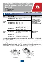
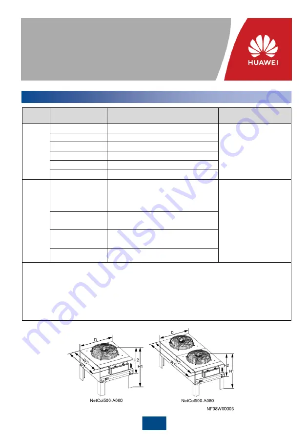
Product Overview
Item
Product Model
Dimensions Without Packing
(H x W x D) (mm)
Optional Component
Indoor
unit
NetCol8000-A045D
2000 x 900 x 900
Electric heater and wet
film humidifier, differential
pressure sensor, water
leakage sensor,
temperature and humidity
sensor
NetCol8000-A045U
2000 x 900 x 900
NetCol8000-A060D
2000 x 1100 x 1000
NetCol8000-A060U
2000 x 1100 x 1000
NetCol8000-A090D
2000 x 1800 x 1000
NetCol8000-A120D
2000 x 2200 x 1000
Outdoor
unit
NetCol500-A060
Category B: D = 1094, W1 = 1356, W2 =
1217, H1 = 1107, H2 = 655
Category C: D = 1094, W1 = 1356, W2 =
1217, H1 = 1156, H2 = 725
Low-temperature
component
NetCol500-A080
D = 1094, W1 = 2186, W2 = 2047, H1 =
1107, H2 = 655
NetCol500-A120
D = 2189, W1 = 1356, W2 = 1217, H1 =
1107, H2 = 655
NetCol500-A110
D = 2189, W1 = 2250, H1 =1769
NetCol8000-A045 and NetCol8000-A060 is a single-system unit. NetCol8000-A090 and NetCol8000-
A120 is a dual-system unit.
NetCol500-A060, NetCol500-A080 and NetCol500-A110 are single-system units. NetCol500-A120 is
a dual-system unit.
A single-system indoor unit is used with a single-system outdoor unit; two single-system indoor units
are used together with a dual-system outdoor unit; a dual-system indoor unit is used with two single-
system outdoor units; a dual-system indoor unit is used with a dual-system outdoor unit.
1
Issue: 02
Part Number: 31500BLY
Date: 2020-04-20
NetCol8000-A (045, 060, 090, 120) In-
room Air Cooled Smart Cooling Product
Quick Guide


