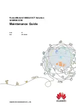
background image


FusionModule1000A40 ICT Solution


V200R003C00


Maintenance Guide


Issue 

01


Date 

2019-03-05


HUAWEI TECHNOLOGIES CO., LTD. 


Summary of Contents for FusionModule1000A40 ICT Solution

Page 1: ...FusionModule1000A40 ICT Solution V200R003C00 Maintenance Guide Issue 01 Date 2019 03 05 HUAWEI TECHNOLOGIES CO LTD ...

Page 2: ...stomer All or part of the products services and features described in this document may not be within the purchase scope or the usage scope Unless otherwise specified in the contract all statements information and recommendations in this document are provided AS IS without warranties guarantees or representations of any kind either express or implied The information in this document is subject to ...

Page 3: ...ds of the FusionModule1000 Intended Audience This document is intended for Maintenance engineers Technical support engineers System engineers Hardware installation engineers Commissioning engineers Data configuration engineers Symbol Conventions The symbols that may be found in this document are defined as follows Symbol Remarks Indicates an imminently hazardous situation which if not avoided will...

Page 4: ...ioration or unanticipated results NOTICE is used to address practices not related to personal injury Calls attention to important information best practices and tips NOTE is used to address information not related to personal injury equipment damage and environment deterioration Change History Changes between document issues are cumulative The latest document issue contains all updates made in pre...

Page 5: ...4 Daily Maintenance 15 3 5 Monthly Maintenance 17 3 5 1 Power Supply and Distribution System 17 3 5 2 Cooling System 17 3 5 3 Monitoring System 18 3 5 4 Fire Extinguishing System Standard 22 3 5 5 Fire Extinguishing System CE 24 3 5 6 Other Systems 25 3 6 Quarterly Maintenance 26 3 6 1 Monitoring System 26 3 6 2 Fire Extinguishing System Standard 32 3 6 3 Fire Extinguishing System CE 33 3 6 4 Othe...

Page 6: ...wer PDB 66 4 1 11 Replacing a Battery Bus Box 67 4 2 Replacing Cooling System Components 67 4 2 1 Replacing Components for Cooling System 67 4 2 2 Replacing an Air Cooled In row Precision Air Conditioner 68 4 2 3 Replacing a Remote T H Sensor for an Air Conditioner 92 4 2 4 Optional Replacing a Low Temperature Component 93 4 3 Replacing Monitoring System Components 93 4 3 1 Replacing an ECC800 Mai...

Page 7: ...Abort Switch Standard 132 4 4 1 8 Replacing Batteries for the Fire Alarm Control Panel Standard 134 4 4 1 9 Replacing a Fire Cylinder Standard 136 4 4 1 10 Replacing a Fire Alarm Control Panel Standard 143 4 4 1 11 Replacing an Emergency Light Standard 146 4 4 2 Replacing Fire Extinguishing System Devices CE 147 4 4 2 1 Replacing a Smoke Detector CE 147 4 4 2 2 Replacing a Heat Detector CE 148 4 4...

Page 8: ...generate electric arcs or sparks which may cause fire or hurt human eyes Before removing component cables mark the cables with their corresponding port numbers for later connection Before connecting a power cable check that the label on the power cable is correct For the detailed power control relationships between devices see the power distribution system diagram for the solution in use During ba...

Page 9: ...form O M for the management system Routine maintenance for the management system is critical for long term stable and efficient operation of the FusionModule1000 because most alarms are reported over the management system Promptly handle reported alarms to prevent equipment damage or service interruption Check and calibrate the hydrogen detection equipment sensors half a year within the sensor ser...

Page 10: ...o Ltd 3 2 Operation and Maintenance Preparations 2 1 Tools Prepare tools listed in Table 2 1 before performing O M operations Table 2 1 Tools Tools Phillips screwdriver Flat head screwdriver Adjustable wrench Electrician s knife Needle nose pliers Diagonal pliers Crimping tool Wire stripper RJ45 crimping tool Cable cutter Hex key Socket wrench ...

Page 11: ...ctroprobe Network cable tester Heat gun Utility knife Step ladder 2 m Cable tie Insulation tape ESD wrist strap ESD gloves Protective gloves Clamp meter ESD floor suction plate Vacuum cleaner The listed tools are for routine maintenance only Prepare other tools as required 2 2 Container Entry Requirements The following describes the requirements for working in the FusionModule1000 Item Requirement...

Page 12: ... measures before entering the FusionModule1000 and performing any operation which may affect the normal running of the FusionModule1000 Do not perform any unauthorized operations After all work is finished Pack up the tools and surplus materials Clean up and organize the equipment room environment according to environment requirements Accept the operations and make records about any operations per...

Page 13: ...ardware and software of the container data center familiar with basic communications protocols familiar with equipment interfaces in extra low voltage ELV systems and proficient in operating the NetEco management system With ELV engineer qualifications Fire extinguishin g system Familiar with the fire extinguishing system configurations and the operations for each core component in the FusionModul...

Page 14: ...ontainer surface is bumped scratched or rusted the paint should be repaired Check the damage to the container paint and prepare appropriate tools and materials The number of materials depends on site requirements Table 3 1 Paint repair Paint Damage Tools and Materials Procedure Description Slight scratch steel base material not exposed Spray paint or paint brush required for repainting a small are...

Page 15: ... paint coating should be thin and even Paint drops are prohibited on the coating The surface should be smooth 5 Leave the repainted area for about 30 minutes before performing any further operation LOGO and pattern damage Seek help from Huawei headquarters for a detailed painting solution Frontline personnel can turn to local advertisement coating suppliers Dent 1 If a dent is less than 100 mm2 in...

Page 16: ...p 2 Dip a piece of cotton cloth into anhydrous alcohol and wipe the polished or damaged area to remove the dirt and dust Then wipe off the alcohol with a clean and dry cotton cloth as shown in Figure 3 2 Figure 3 2 Wiping a polished or damaged area using anhydrous alcohol Step 3 Paint one layer of zinc rich primer on the damaged coat using a brush or painting gun as shown in Figure 3 3 ...

Page 17: ...e damage degree of the paint described in Table 3 1 using a spray bottle brush or painting gun respectively shown in Figure 3 4 Figure 3 5 and Figure 3 6 In the case that a container pattern has different colors to prevent undamaged areas and those with different colors as the damaged area from being polluted during repainting cover such areas using white paper and adhesive tape before repairing p...

Page 18: ...p Procedure Check whether the surface meets the requirement after repainting The repainted area should have the same color as surrounding areas The color difference δE is not greater than 3 Use a colorimeter to measure the color difference If a colorimeter is not available check that no obvious edge exists between the repainted area and its surrounding The paint should also be free from bulges scr...

Page 19: ...mities on both sides from one extremity to the other or from one extremity to the middle Sliding a Cabinet from the Middle to Extremities on Either Side Step 1 Unlock the base indexing plunger handles 1 Pull the indexing plunger handles at the front and rear of the sliding bases of the cabinet 2 Turn the indexing plunger handles at the front and rear of the sliding bases by 90 to unlock the handle...

Page 20: ...ide the cabinet End Sliding a Cabinet from one Extremity to the Other Extremity The method is similar to that for sliding a cabinet from the middle to extremities on both sides For details see Sliding a Cabinet from the Middle to Extremities on Either Side Sliding a Cabinet from one Extremity to the Middle Step 1 Verify that the indexing plunger in the cabinet sliding direction is unlocked and tha...

Page 21: ...extinguishing compartment Before maintaining the fire cylinder you need to operate the shutter Procedure Step 1 Pull the beaded rope at the side of the shutter in the fire extinguishing compartment until all blades of the shutter are perpendicular to the guide rail at the top Figure 3 10 Rotating the shutter blades Step 2 Pull the rope at the side of the shutter in the fire extinguishing compartme...

Page 22: ...ire cylinder restore the shutter by referring to the operations in Step 2 to Step 1 3 4 Daily Maintenance Table 3 2 Daily maintenance checklist Categ ory Mainten ance Item Operation Check Standard Troubleshooting Power supply and distribu PDC Check the luminance of the indicators The three phase power indicators are steady on If an indicator is off or dim replace it For details refer to 4 1 8 5 Re...

Page 23: ...entation Alarm short messages can be received Check whether the SIM card is properly installed If the SIM card is faulty replace it by following instructions in ECC800 Data Center Controller V100R001C30 User Manual Camera images and coverage On the ECC800 WebUI choose System Settings Video Settings Video Information in the monitoring system and you can click Access Link on the page to access the v...

Page 24: ... it by following instructions in 4 1 8 4 Replacing the SPD in a PDC 2 Switch on the circuit breaker Push any button on the PD510 electricity meter LCD The PD510 electricity meter LCD lights up and displays information properly 1 If the LCD does not display information properly no display or fuzzy check whether the power cable is properly connected 2 If the power cable is correctly connected replac...

Page 25: ...indicator The green indicator is steady on Power input Dual input voltage range 43 58 V DC rated voltage 53 5 V DC If the input voltage is abnormal check the power grid and input cable connection Power output Voltage range 43 58 V DC rated voltage 53 5 V DC For details contact Huawei technical support Operating environment Temperature 20 C to 65 C Humidity 5 95 RH non condensing Check that the amb...

Page 26: ... 1s or registration with the ECC800 is successful Blinking at short interval The communication is interrupted or the registration with the ECC800 fails the indicator blinks at 4 Hz on for 0 125s and then off for 0 125s Blinking The indicator blinks at super short intervals for 0 5s blinking at 10 Hz on for 0 05s and then off for 0 05s and then turns off for 0 5s The cycle lasts for 10s Check the p...

Page 27: ...nd then off for 0 05s Blinking at super short intervals intermittently The device is searching for a network the indicator blinks at 2 Hz on for 0 5 and then off for 0 5s Refer to ECC800 Data Center Controller V100R001C30 User Manual to register the device or contact Huawei technical support Table 3 6 Monthly maintenance checklist for the monitoring system Check Item Operation Check Standard Troub...

Page 28: ...Blinking slowly The software runs properly the indicator blinks at 0 5 Hz on for 1s and then off for 1s or registration with the ECC800 is successful Blinking at short interval The communication is interrupted or the registration with the ECC800 fails the indicator blinks at 4 Hz on for 0 125s and then off for 0 125s Blinking The indicator blinks at super short intervals for 0 5s blinking at 10 Hz...

Page 29: ...searching for a network the indicator blinks at 2 Hz on for 0 5 and then off for 0 5s Refer to ECC800 Data Center Controller V100R001C30 User Manual to register the device or contact Huawei technical support Pad Exterior The exterior is intact and the touchscreen is working properly Replace the pad Exit button Function The function is normal Replace by following instructions in 4 3 11 2 Replacing ...

Page 30: ... cylinder by following instructions in 4 4 1 9 Replacing a Fire Cylinder Standard For details about how to replace other devices contact Huawei technical support All devices of the fire extinguisher are free from rust on the exterior and the coating is intact Repaint The lead seal and safety signs on hand operated devices are intact Replace the electromagnetic valve Read the pressure shown on the ...

Page 31: ...hing System CE Table 3 8 Monthly maintenance checklist for the fire extinguishing system Device Operation Check Standard Maintenance Guide Extinguisha nt control panel Check indicators on the extinguishant control panel The power indicator turns on and the alarm indicator turns off Replace by following instructions in 4 4 2 10 Replacing the Extinguishant Control Panel CE Batteries of the fire alar...

Page 32: ...ng instructions in 4 4 2 11 Replacing an Emergency Light CE Smoke detector Check the smoke detector indicator The indicator blinks once every 6s Replace by following instructions in 4 4 2 1 Replacing a Smoke Detector CE Heat detector Check the heat detector indicator The indicator blinks once every 6s Replace by following instructions in 4 4 2 2 Replacing a Heat Detector CE 3 5 6 Other Systems Tab...

Page 33: ...he containers meet requirements The external temperature and solar radiation requirements of the FusionModule 1000 are as follows Temperatur e Normal tempera ture 20 C to 55 C Low tempera ture 40 C to 45 C Humidity 5 95 RH Solar radiation 1120 W m2 For details contact Huawei technical support 3 6 Quarterly Maintenance 3 6 1 Monitoring System Table 3 10 Quarterly maintenance checklist for the monit...

Page 34: ... support RUN indicator Off The power supply is abnormal Blinking slowly The software runs properly the indicator blinks at 0 5 Hz on for 1s and then off for 1s or registration with the ECC800 is successful Blinking at short interval The communication is interrupted or the registration with the ECC800 fails the indicator blinks at 4 Hz on for 0 125s and then off for 0 125s Blinking The indicator bl...

Page 35: ...short intervals intermittently The device is searching for a network the indicator blinks at 2 Hz on for 0 5 and then off for 0 5s Refer to ECC800 Data Center Controller V100R001C30 User Manual to register the device or contact Huawei technical support AC actuator Power input Input voltage 90 240 V AC Check the input power cables if the input voltage is abnormal Power output Output voltage 90 240 ...

Page 36: ... 1s or registration with the ECC800 is successful Blinking at short interval The communication is interrupted or the registration with the ECC800 fails the indicator blinks at 4 Hz on for 0 125s and then off for 0 125s Blinking The indicator blinks at super short intervals for 0 5s blinking at 10 Hz on for 0 05s and then off for 0 05s and then turns off for 0 5s The cycle lasts for 10s Check the p...

Page 37: ...ng at super short intervals intermittently The device is searching for a network the indicator blinks at 2 Hz on for 0 5 and then off for 0 5s Refer to ECC800 Data Center Controller V100R001C30 User Manual to register the device or contact Huawei technical support WiFi converter Power input Input voltage 36 60 V DC Check the input power cables if the input voltage is abnormal WiFi indicator Steady...

Page 38: ...pply Refer to ECC800 Data Center Controller V100R001C30 User Manual to register the device or contact Huawei technical support WPS indicator On The WPS is working properly Blinking The WPS is in matching mode If the matching fails the WPS indicator turns off after blinking for 2 minutes If the matching is successful the WPS indicator turns off For details contact Huawei technical support Door stat...

Page 39: ... If the fuse is blown replace the fuse 2 Perform replacement by following instructions in 4 4 1 8 Replacing Batteries for the Fire Alarm Control Panel Standard Hand held fire extinguishe r Check the fire extinguisher The fire extinguisher is intact Replace the fire extinguisher The pressure pointer of the fire extinguisher is in the green zone Replace the fire extinguisher The fire extinguisher is...

Page 40: ...el CE Hand held fire extinguishe r Check the hand held fire extinguisher The hand held fire extinguisher is in good condition Replace the hand held fire extinguisher The pressure pointer of the hand held fire extinguisher is in the green zone The fire extinguisher is within the validity period 3 6 4 Other Systems Table 3 13 Quarterly maintenance checklist for other systems Item Method Check Standa...

Page 41: ...1 If the panel indicator is off verify that the power cable is properly connected and reconnect the cable if it is not properly connected 2 Replace the ATS by following instructions in documents delivered with the ATS The display panel of the controller displays information properly 1 If the information is not properly displayed fuzzy or blank verify that the power cable is properly connected 2 Re...

Page 42: ... if no monitoring system is configured N A Rectify the fault or contact Huawei technical support Electric heater The electric heater is secure The electric heater is securely installed Secure the electric heater and switch Check that the electric heater surfaces are not eroded The electric heater surface is not corroded Replace the electric heater if its surface is eroded Compon ents inside the el...

Page 43: ...om signs of aging Replace the abnormal board Check that all contactors work properly Contactors work properly and smoothly Replace abnormal components Cable Check that no cable has aged Cables are not aged Replace aged cables Tempera ture and humidity T H sensor Check and calibrate the T H sensor The T H sensors are working properly and the temperature and humidity deviations are within the allowe...

Page 44: ... the indicator blinks at 0 5 Hz on for 1s and then off for 1s or registration with the ECC800 is successful Blinking at short interval The communication is interrupted or the registration with the ECC800 fails the indicator blinks at 4 Hz on for 0 125s and then off for 0 125s Blinking The indicator blinks at super short intervals for 0 5s blinking at 10 Hz on for 0 05s and then off for 0 05s and t...

Page 45: ...ault persists contact Huawei technical support and ask the hydrogen exhaust fan to be replaced 3 7 4 Fire Extinguishing System Standard Semi annual maintenance of the fire extinguishing system involves system commissioning Before the maintenance inform the related administrative departments that the fire extinguishing system will be maintained and stop working Before the maintenance disconnect all...

Page 46: ...under Unlock the fire alarm control panel and press ALARM BELL The alarm is loud and clear 1 Check and reconnect cables to the fire alarm sounder 2 If the fault persists replace by following instructions in 4 4 1 6 Replacing a Fire Alarm Sounder Standard Gas release indicator Disconnect the red and black cables from the pressure announciator and short circuit the cables from the fire alarm control...

Page 47: ...Replace by following instructions in 4 4 1 1 Replacing a Smoke Detector Standard If the smoke density exceeds the alarm threshold the indicator turns on The fire alarm control panel generates an alarm and triggers the fire alarm sounder If the fault persists replace by following instructions in 4 4 1 1 Replacing a Smoke Detector Standard Fire alarm horn strobe Unlock the fire alarm control panel a...

Page 48: ...enerates an alarm in 120s See documents delivered with the VESDA The VESDA panel displays an alarm See documents delivered with the VESDA Check the VESDA operation panel All indicators are normal See documents delivered with the VESDA Check whether the backup power is working properly and whether the VESDA restarts normally after the mains powered is disconnected The backup power is working proper...

Page 49: ...Check Standard Maintenance Guide Fire extinguishi ng system commission ing Commission the fire extinguishing system by following the instructions in the Fire Extinguishing System Commissioning CE section in the commissioning guide for the solution in use Devices work properly and the management system displays related alarms Replace by following instructions in 4 4 2 Replacing Fire Extinguishing S...

Page 50: ...he smoke density is below the alarm threshold the alarm indicator blinks once every 6s 2 If the smoke density is above the alarm threshold the indicator turns on The extinguishant control panel generates an alarm and triggers the fire alarm bell Replace by following instructions in 4 4 2 1 Replacing a Smoke Detector CE Extinguisha nt abort button 1 After the manual gas release button is pressed on...

Page 51: ... the VESDA Release smoke to the furthest end of a VESDA sampling pipe The VESDA generates an alarm in 120s See documents delivered with the VESDA The VESDA panel displays an alarm See documents delivered with the VESDA Check the VESDA operation panel All indicators are normal See documents delivered with the VESDA Check whether the backup power is working properly and whether the VESDA restarts no...

Page 52: ... If an air filter is slightly blocked clean the air filter and reinstall it If more than 50 of the meshes are blocked replace the air filter Cable trays inside containers Check whether the cable trays are securely connected without damage or misshapen Cable trays are properly installed and fasteners are secure Secure cable trays that have become loose Cable trays screws and nuts are free from rust...

Page 53: ...ubleshooting Check whether cables are intact Cable jackets are free from damage or cracks No cable overheats due to overload and the loads are within the rated capacity of the cables the cables works only a very short time under overload situations The bend radius of cables meets requirement s The cable armor is intact Replace parts that do not meet requirements ...

Page 54: ... system may need to be powered off Take measures to prevent device overheating Table 4 1 lists the components that can be replaced for the power supply and distribution system Table 4 1 Components that can be replaced for the power supply and distribution system Device Component Name Reference Document Integrated UPS 2 0 Fuse UPS5000 E 40 kVA 128 kVA User Manual Integrated UPS 2 0 Indicator Integr...

Page 55: ...rminal Check that the standby power supply to the rPDU is available Impact on the System None Preparations Tools Phillips screwdriver protective gloves step ladder Material spare rPDU Documents none Skill requirement electrician s work permit Procedure Step 1 Switch off the circuit breaker of the faulty rPDU in the PDC Step 2 Remove all power connectors from the rPDU Step 3 Remove the baffle plate...

Page 56: ... them on a new rPDU Step 8 Mount the new rPDU with a support into the cabinet and tighten the fastening screws of the rPDU using a Phillips screwdriver as shown in Figure 4 2 Figure 4 2 Installing screws at the upper and lower sides of the rPDU Step 9 Connect the rPDU power cable on the top of the cabinet Step 10 Switch on the circuit breaker for the rPDU in the PDC and check that the new rPDU is ...

Page 57: ... electrician s work permit For the diagram see the initial configuration parameter manual for the solution in use Procedure Step 1 Power off the STS based on the power supply and distribution system diagram Step 2 Remove cables connected to the STS and remove screws securing the STS Step 3 Install a new STS connect the cables and secure the STS using screws End Follow up Procedure Dispose of the r...

Page 58: ...n system diagram Step 3 Remove cables from the faulty battery using a wrench and insulate the cables Step 4 Move the faulty battery out of the battery rack Ensure human safety during the movement Step 5 Install the new battery and connect cables correctly based on battery wiring diagram Step 6 Verify the battery connections Ensure that the battery quantity and cable connections comply with the des...

Page 59: ...les Step 4 Move the faulty battery out of the battery rack Ensure human safety during the movement Step 5 Install the new battery and connect cables correctly based on the DC power system battery wiring diagram Step 6 Verify the battery connections Ensure that the battery quantity and cable connections comply with the design and the cables or copper bars are reliably installed Step 7 Switch on the...

Page 60: ...battery in the battery switch box based on the power supply and distribution system diagram and remove cables from the rear of the battery pack Step 2 Remove screws from the cabinet and remove the battery pack Step 3 Loosen the battery pack and remove screws from the battery pack mounting ears Step 4 Install the mounting ears on the new battery pack using eight M4 screws Figure 4 3 Installing moun...

Page 61: ...llow up Procedure Dispose of the removed batter pack that is confirmed faulty 4 1 7 Replacing a Light Prerequisites Spare LED lights of the same model are available and functional Impact on the System None Preparations Tools multimeter Material spare light Documents none Skill requirement electrician s work permit Procedure Step 1 Locate a failed light If a light does not work but the cables to th...

Page 62: ... Replacing an ATS Controller Prerequisites A spare ATS controller of the same model is available and functional Impact on the System Certain services of the FusionModule1000 are interrupted Preparations Tools Phillips screwdriver flat head screwdriver key to the PDC door step ladder Materials spare ATS controller Documents documents delivered with the PDC power supply and distribution device layou...

Page 63: ...ob Step 6 Reinstall the protective panel of the PDC Step 7 Switch on the upstream input and output circuit breakers of the PDC Step 8 Check that the new ATS controller is working properly After power on the Power indicator of the controller lights up Step 9 Switch on downstream circuit breakers of the PDC End 4 1 8 2 Replacing an MCB Prerequisites A spare MCB of the same model is available and fun...

Page 64: ...tch If the voltage is lower than 36 V DC for 1 minute replace the MCB Step 4 Remove the three cables from the top and bottom of the MCB When removing cables remove the cable from the bottom of the MCB first After removing cables insulate the cable terminals When removing cables label the cables with corresponding terminal ports for later connection Step 5 Push the buckle at the MCB outwards using ...

Page 65: ...Switch off the upstream circuit breaker of the electricity meter Step 3 Remove the terminal block from the PD510 electricity meter and gently press the latch outwards to remove the terminal block Step 4 Remove the faulty PD510 electricity meter and install a new PD510 electricity meter and insert the latch Step 5 Install the removed terminal block and ensure that the terminal block is connected pr...

Page 66: ...ations Tools Phillips screwdriver flat head screwdriver electroprobe Material spare SPD Documents PDC user manual Skill requirement electrician s work permit Procedure Step 1 Remove the protective panel of the SPD Avoid touching any charged body when removing the panel Step 2 Switch off the SPD circuit breaker Step 3 Detect the L1 L2 L3 and N voltages to the PE using an electrical tester pen and v...

Page 67: ...D module it is recommended that all SPD modules be replaced If the SPD module cannot be pulled out use a tool such as a flat head screwdriver to lever it out Step 5 Install the spare SPD module and switch on the SPD circuit breaker Step 6 Reinstall the protective panel End Follow up Procedure Dispose of the removed SPD module that is confirmed faulty 4 1 8 5 Replacing an Indicator Prerequisites An...

Page 68: ...ace the indicator if no voltage is detected by using a multimeter Step 3 Loosen the screw at the rear of the indicator and remove the conducting wire Figure 4 8 Removing an indicator When removing cables label the cables with corresponding terminal ports for later connection Step 4 Remove the retaining ring from the indicator and remove the indicator from the mounting hole Step 5 Install a new ind...

Page 69: ...d functional When replacing a fuse you must wear insulated gloves and must not touch the input copper bar Impact on the System None Preparations Tools insulation gloves Materials spare fuse Documents none Skill requirement electrician s work permit Procedure Step 1 Shake the fuse terminal block gently pull it out and push it outwards The fuse position in the figure is for reference only The actual...

Page 70: ... block in the PDC Step 4 Check whether the new fuse works properly End Follow up Procedure Dispose of the removed fuse that is confirmed faulty 4 1 8 7 Replacing an Ambient T H Sensor Prerequisites A spare ambient T H sensor of the same model is available and functional Impact on the System None Preparations Tools key to the cabinet door diagonal pliers Materials spare ambient T H sensor cable tie...

Page 71: ... in communication If multiple BIMs need to be replaced replace them in ascending order of the corresponding battery numbers range 1 300 Prerequisites A spare BIM of the same model is available and functional Impact on the System None Preparations Tools none Materials spare BIM Documents none Skill requirement extra low voltage ELV engineer Procedure Step 1 Press the CIM networking switch for 2 sec...

Page 72: ...he home screen of the CIM WebUI choose Monitoring CIM System Running Control click BIM start blinking select the corresponding battery number from the range of 1 300 and click Submit If the BIM blinks successfully the installation succeeds If the BIM fails in blinking check the cable connections and reinstall the BIM Figure 4 11 Setting the BIM blinking If the BIM blinks successfully click BIM sto...

Page 73: ...k Internal resistance select a battery number and click Submit to measure the internal resistance of the battery End Follow up Procedure Dispose of the removed BIM that is confirmed faulty 4 1 10 Replacing the Power PDB Prerequisites A spare power PDB of the same model is available and functional Impact on the System None Preparations Tools Phillips screwdriver socket wrench Materials spare power ...

Page 74: ...ure Step 1 Power off the BBB based on the power supply and distribution system diagram Step 2 Remove cables using a socket wrench and Phillips screwdriver Step 3 Remove screws securing the BBB and remove the BBB Step 4 Secure the new BBB and connect cables correctly End Follow up Procedure Dispose of the removed BBB that is confirmed faulty 4 2 Replacing Cooling System Components 4 2 1 Replacing C...

Page 75: ...ssor Compressor driver Humidifier cylinder Electric control box Temperature and humidity T H sensor Module Liquid level detector Water pump LCD 21 kW air cooled in row precision air conditioner Air filter NetCol5000 A 21 kW Air Cooled In row Precision Air Conditioner User Manual 208 V Indoor fan Transformer Compressor Humidifier cylinder Electric control box Temperature and humidity T H sensor Mod...

Page 76: ... cold aisle inside the pre fab module For example to replace air conditioner A1 or B1 in Figure 4 12 you need to push cabinets A1 A2 B1 and B2 on both sides of cold aisle A to the extremities towards the hot aisle and replace the air conditioner in cold aisle A Similarly air conditioner C1 or D1 can be replaced in cold aisle B Figure 4 12 Pre fab module layout 1 Cold aisle A 2 Cold aisle B Air con...

Page 77: ...nd distribution system diagram cooling device initial configuration table Skill requirement cooling engineer For the table see the initial configuration parameter manual for the solution in use Procedure Step 1 Locate the cold aisle containment where maintenance is to be performed based on the position of the faulty air conditioner Step 2 Remove the suspended ceilings in the cold and hot aisles ad...

Page 78: ...sle Assign two persons to remove a decorative beam together One person holds up the decorative beam while the other person removes the fasteners Figure 4 14 Removing a decorative beam 1 Remove the sealing ring from the decorative beam 2 Remove bolts securing the decorative beam using a Phillips screwdriver and remove the decorative beam Step 4 Optional Remove the bolts securing the sealing plate a...

Page 79: ...19 03 05 Copyright Huawei Technologies Co Ltd 72 Figure 4 15 Removing the top sealing plate from the air conditioner Step 5 Remove the floors under the front and rear of the air conditioner Figure 4 16 Removing floors 1 ESD floor in the cold aisle 2 Ventilation floor in the hot aisle ...

Page 80: ...ips screwdriver Step 6 Remove the front and rear sealing plates from the air conditioner base Figure 4 17 Removing sealing plates from the air conditioner base 1 Remove the floor tray and baffle plate from the supportive legs at the rear of the air conditioner 2 Optional Remove the bolts securing the base sealing plate at the rear of the air conditioner using a Phillips screwdriver and remove the ...

Page 81: ...d Adjust the height of the floor tray to ensure that the reinstalled floor panels are flush with other floor panels Step 8 Remove fasteners from the top and bottom of the air conditioner Figure 4 18 Removing air conditioner fasteners 1 Remove the four M10 bolts at the top of the air conditioner using an adjustable wrench 2 Remove the four M12 bolts at the bottom of the air conditioner using a sock...

Page 82: ...oner 1 Switch off the integrated UPS circuit breaker that supplies power to the air conditioner to power off the air conditioner indoor unit For details see the power supply and distribution system diagram for the solution in use 2 Verify that the LCD on the air conditioner front door is powered off 3 Open the locks on the front and rear doors of the air conditioner using keys and open the air con...

Page 83: ...ce of 150 mm Step 10 Remove the air conditioner cables 1 Switch off the integrated UPS circuit breaker that supplies power to the air conditioner indoor unit and verify that the air conditioner indoor unit is powered off using a multimeter before proceeding with the following operations 2 Before replacing cables record the cable routes to ensure that the cable routes are the same before and after ...

Page 84: ...acement Issue 01 2019 03 05 Copyright Huawei Technologies Co Ltd 77 Figure 4 21 Removing the active and standby power cables from the air conditioner 2 Remove the power cable for the air conditioner outdoor unit from port AC3 on the air conditioner indoor unit PDB ...

Page 85: ...ement Issue 01 2019 03 05 Copyright Huawei Technologies Co Ltd 78 Figure 4 22 Removing the power cable from the air conditioner outdoor unit 3 Remove the communications cables between the indoor and outdoor units of the air conditioner 4 Remove the water sensor cable ...

Page 86: ...t Huawei Technologies Co Ltd 79 Figure 4 23 Removing the air conditioner communications cable and water sensor X302 1 2 3 RS485 communications control port for the outdoor unit X301 7 8 water sensor port 5 Remove the teamwork control cable from the FE_1 port on the air conditioner main control module ...

Page 87: ...03 05 Copyright Huawei Technologies Co Ltd 80 Figure 4 24 Removing the air conditioner teamwork cable 6 Remove the remote T H sensor cable at the air return side of the air conditioner from the RS485_OUT port Figure 4 25 Removing the remote T H sensor cable Step 11 Discharge refrigerant ...

Page 88: ...rant verify that refrigerant oil does not flow out of the hose If a small amount of refrigerant oil continually flows out of the hose place a vessel or rag under the hose to catch the refrigerant oil 3 Keep the pressure gauge valve open after the refrigerant draining slows down after a period of time until no refrigerant is obviously flowing out 4 Wear anti freezing gloves and press the needle val...

Page 89: ...air conditioner drainpipe completely out of the air conditioner after removing the drainpipe Coil the water refill hose inside the air conditioner after removing it to avoid influence on the air conditioner movement Drag the copper pipe that goes inside the air conditioner completely out of the air conditioner after cutting the copper pipe to avoid influence on the air conditioner movement Ignore ...

Page 90: ... conditioner pipes Step 13 Move the air conditioner Steel plates and pipes must be placed a certain distance away from the pre fab module side wall to prevent scratching the side wall 1 Take the fittings for moving the air conditioner from the pre fab module fitting bag Fittings for moving an air conditioner include a 3 mm thick steel plate two 1 5 m long DN32 steel pipes and three 0 5 m long DN32...

Page 91: ... 5 m long DN32 steel pipe 4 Push the air conditioner at the back towards the cold aisle at the front Verify that the air conditioner front bottom will be on the steel pipe placed in Step 13 3 after the air conditioner is pushed about 100 mm away from the base This step requires two persons working together one pushing the air conditioner from behind and the other pulling the air conditioner at the...

Page 92: ...r conditioner until the front of air conditioner D1 is 100 mm away from the front of air conditioner C1 6 Place the other 1 5 m long DN32 steel pipe above the 3 mm thick steel plate about 100 mm away from the base of air conditioner D1 To make it easier to place the air conditioner onto the steel pipes in front of it you can pull the air conditioner backwards at the top to increase the space at th...

Page 93: ...gure 4 31 Pushing the air conditioner 2 1 1 5 m long DN32 steel pipe 7 Continue pushing forward the air conditioner until it is separated from the base and placed onto the two steel pipes Adjust the positions of the two steel pipes and the distance in between to ensure that the air conditioner is evenly carried on the two steel pipes ...

Page 94: ...gure 4 32 Pushing the air conditioner 3 Step 14 Refer to 3 2 Sliding Cabinets to push cabinets C1 C2 D1 and D2 towards the hot aisle to the extremities and lock the sliding bases under the cabinets After the cabinets are slid to the extremities air conditioner D1 must be completely inside the cold aisle and must not touch any cabinet ...

Page 95: ...t Huawei Technologies Co Ltd 88 Figure 4 33 Air conditioner position 1 Air conditioner D1 2 Air conditioner C1 Step 15 Pull the air conditioner 1 Remove the side sealing plate from the air conditioner bottom at the long aisle side Figure 4 34 Removing the sealing plate from the air conditioner bottom ...

Page 96: ... long aisle until the air conditioner reaches the cold aisle entrance After moving the air conditioner by about 300 mm the other person can go to the other side of the air conditioner to push the air conditioner Figure 4 35 Moving the air conditioner 1 3 Place the three 0 5 m long DN32 steel pipes evenly in the long aisle near the entrance of cold aisle B 4 Push air conditioner D1 completely onto ...

Page 97: ...pyright Huawei Technologies Co Ltd 90 Figure 4 36 Moving the air conditioner 2 5 Move the air conditioner out of the pre fab module using a forklift Step 16 Install a new air conditioner 1 Remove the support from the top of air conditioner D1 and install it on the top of the new air conditioner ...

Page 98: ...erify that there is no gap between the fasteners at the top Figure 4 38 Securing fasteners at the air conditioner top 3 Perform Step 15 to Step 2 to install the new air conditioner and connect structural kits pipes and cables 4 Perform power on commissioning for the air conditioner to verify that the new air conditioner is working properly For details see documents delivered with the air condition...

Page 99: ... Skill requirement cooling engineer For the table see the initial configuration parameter manual for the solution in use Procedure Step 1 Remove the network cable from the remote T H sensor as shown in Figure 4 39 Figure 4 39 Removing the network cable from the remote T H sensor Step 2 Remove the faulty remote T H sensor install a new remote T H sensor and reconnect the network cable to the sensor...

Page 100: ...lation position diagram Skill requirement cooling engineer common technician For the diagrams see the initial configuration parameter manual for the solution in use Procedure Step 1 Remove the faulty low temperature component Step 2 Attach the new low temperature component to the original position Step 3 Connect the power cable of the low temperature component to the nearest power socket on the pr...

Page 101: ...nformation Step 2 Label each cable and antenna based on the corresponding ports on the ECC800 main control module Step 3 Remove the cables and antenna from the ECC800 main control module Step 4 Remove the old ECC800 main control module which is hot swappable Step 5 Optional Remove the SIM card from the corresponding slot on the side of the old ECC800 main control module Step 6 Optional Install the...

Page 102: ...quirement extra low voltage ELV engineer Procedure Step 1 Push the locking latch in the upper right corner of the ECC800 PSU panel leftwards to open the lock Step 2 Pull out ECC800 PSU from the subrack by the handle Step 3 Place a spare ECC800 PSU in the subrack push the locking latch leftwards to open the lock and pull the handle outwards Step 4 Gently push the ECC800 PSU into the subrack along g...

Page 103: ...arations Tools insulation gloves Materials spare ECC800 PSU Documents ECC800 user manual Skill requirement extra low voltage ELV engineer Procedure Step 1 Remove the ECC800 power cable Step 2 Push the locking latch in the upper right corner of the ECC800 PSU panel leftwards to open the lock Step 3 Pull out ECC800 PSU from the subrack by the handle Step 4 Place a spare ECC800 PSU in the subrack pus...

Page 104: ...rerequisites A spare AI DI module of the same model is available and functional Impact on the System Components connected to the AI DI module may generate false alarms Preparations Tools Phillips screwdriver flat head screwdriver Materials spare AI DI module insulation tape Documents management system initial configuration table Skill requirement extra low voltage ELV engineer For the table see th...

Page 105: ...n AI DI module Step 4 Connect cables to the new AI DI module Step 5 Configure the AI DI module based on the management system initial configuration table End Follow up Procedure Dispose of the removed AI DI module that is confirmed faulty 4 3 5 Replacing a Smart ETH Gateway Prerequisites A spare ETH gateway of the same model is available and functional Impact on the System Devices connected to the...

Page 106: ...s End Follow up Procedure Dispose of the removed ETH gateway that is confirmed faulty 4 3 6 Replacing a Camera Prerequisites A spare camera of the same model is available and functional Impact on the System Video surveillance stops Preparations Tools Phillips screwdriver step ladder protective gloves Material spare camera Documents documents delivered with the camera management system initial conf...

Page 107: ...t Huawei Technologies Co Ltd 100 Figure 4 43 Removing screws securing the transparent cover Step 2 Use a Phillips screwdriver to remove the screws that fasten the camera to its base Figure 4 44 Removing screws that secure the camera to its base Step 3 Remove the network cable and take out the camera ...

Page 108: ...ew camera is working properly End Follow up Procedure Dispose of the removed camera that is confirmed faulty 4 3 7 Replacing an External Camera Prerequisites A spare external camera of the same model is available and functional Impact on the System None Preparations Tools Phillips screwdriver 1 and 2 Material spare external camera Documents documents delivered with the external camera external cam...

Page 109: ...sites A spare signal SPD of the same model is available and functional Impact on the System None Preparations Tool Phillips screwdriver Materials signal SPD Documents signal SPD installation position diagram Skill requirement electrician s work permit For the diagram see the quick installation guide for the solution in use Procedure Step 1 Determine the position for installing the signal SPD based...

Page 110: ...5 Copyright Huawei Technologies Co Ltd 103 Figure 4 45 Removing the signal SPD Step 3 Remove cables connected to the faulty signal SPD and remove the faulty signal SPD Step 4 Install the spare signal SPD and reconnect the cables in the same way Step 5 Reinstall the signal SPD clamping plate ...

Page 111: ...e door of the SPD box End Follow up Procedure Dispose of the removed signal SPD that is confirmed faulty 4 3 9 Replacing an SD Card Prerequisites A spare SD card of the same model is available and functional Impact on the System None Preparations Tools camera screwdriver Materials spare SD card Documents monitoring device layout diagram Skill requirement extra low voltage ELV engineer ...

Page 112: ...ews on the front cover of the camera remove the front cover and take out the inner cover over the lens Figure 4 47 Removing the front and inner covers Step 2 Remove the faulty SD card from the SD card slot Step 3 Insert a new SD card into the SD card slot Figure 4 48 Installing an SD card Step 4 Reinstall the inner and front covers End Follow up Procedure Dispose of the removed SD card that is con...

Page 113: ...ature sensor Documents monitoring device layout management system initial configuration table Skill requirement weak current engineer For the diagrams and tables see the initial configuration parameter manual for the solution in use Procedure Step 1 Locate the water sensor to be replaced based on the alarm information on the monitoring software terminal Figure 4 49 shows a point type water sensor ...

Page 114: ...he new water sensor is working properly Drip a small amount of water onto the water sensor If the monitoring software terminal generates an alarm the water sensor is working properly End Follow up Procedure Dispose of the removed water sensor that is confirmed faulty 4 3 11 Replacing Access Control Components 4 3 11 1 Replacing an IC Card Reader Prerequisites An IC card reader needs to be replaced...

Page 115: ...he door of the IC cared reader box Step 2 Remove the two screws from the bottom of the IC card reader and remove the front cover Figure 4 51 Removing the front cover Step 3 Remove the two screws that secure the IC card reader body Figure 4 52 Removing screws Step 4 Remove interconnection terminals from the IC card reader and remove the IC card reader body Step 5 Remove the two screws from the bott...

Page 116: ...g operations are logged in the monitoring system End Follow up Procedure Dispose of the removed IC card reader that is confirmed faulty 4 3 11 2 Replacing an Exit Button Prerequisites An exit button needs to be replaced A spare exit button of the same model is available and functional Impact on the System None Preparations Tools insulation tape Phillips screwdriver small sized flat head screwdrive...

Page 117: ...r the new exit button is working properly If the container door can be opened using the exit button and the door opening event is logged the new exit button is working properly End Follow up Procedure Dispose of the removed exit button that is confirmed faulty 4 3 11 3 Replacing a Magnetic Lock Prerequisites The magnetic lock needs to be replaced A spare magnetic lock of the same model is availabl...

Page 118: ...kill requirement weak current engineer Procedure Step 1 Use a Phillips screwdriver to loosen screws from the baffle plate of the magnetic lock as shown by 1 in Figure 4 54 Figure 4 54 Removing screws Step 2 Remove cables connected to the magnetic lock Step 3 Use a 3 mm hex key to loosen screws from the baffle plate of the magnetic lock as shown by 2 and 3 in Figure 4 54 Step 4 Replace the magnetic...

Page 119: ... End Follow up Procedure Dispose of the removed magnetic lock that is confirmed faulty 4 3 11 4 Replacing an Emergency Door Release Button Prerequisites The emergency door release button needs to be replaced A spare emergency door release button of the same model is available and functional Impact on the System None Preparations Tools insulation tape step ladder 2 m Phillips screwdriver protective...

Page 120: ... 4 56 Removing the emergency door release button Step 2 Install a new emergency door release button 1 Connect cables 2 Tighten screws on the base as shown by 1 in Figure 4 57 3 Install the glass panel as shown by 2 and 3 in Figure 4 57 4 Tighten screws as shown by 4 in Figure 4 57 Figure 4 57 Installing the emergency door release button Step 3 Check that the new emergency door release button is wo...

Page 121: ...rker Materials spare access actuator Documents none Skill requirement extra low voltage ELV engineer Procedure Step 1 Label each cable based on the corresponding ports on the access actuator Step 2 Disconnect cables from the access actuator Step 3 Remove the faulty access actuator from guide rails Step 4 Install the spare access actuator in the original position and connect the cables End Follow u...

Page 122: ...cedure Step 1 Open the container door where the door status sensor to be replaced is installed Obtain permission from the related administration department before opening a container door Step 2 Open the door status sensor box and disconnect the cable to remove the door status sensor to be replaced Figure 4 58 Replacing a door status sensor Step 3 Install a new door status sensor and reconnect the...

Page 123: ...input circuit breaker for the AC actuator Step 2 Label each cable based on the corresponding ports on the AC actuator Step 3 Open the cover on the front panel of the AC actuator and disconnect the cables Step 4 Remove the faulty AC actuator Step 5 Install the spare AC actuator in the original position and connect the cables Step 6 Switch on the upstream AC input circuit breaker for the AC actuator...

Page 124: ...he WiFi function and set the WiFi SSID and password according to the customer plan Step 6 Check that the app can be connected properly End Follow up Procedure Dispose of the removed WiFi converter that is confirmed faulty 4 3 14 Replacing a Pad Prerequisites A spare pad of the same model is available and functional Impact on the System None Preparations Tools ESD wrist strap ESD gloves label marke...

Page 125: ...User Manual Skill requirement extra low voltage ELV engineer Procedure Step 1 Clear the network parameters for all the BIMs managed by the CIM to be replaced If the CIM is damaged manually clear the network parameters for all the BIMs managed by the CIM by holding down the networking switch for the BIM If the CIM is not damaged hold down the networking switch for the CIM to clear the current netwo...

Page 126: ...User Manual End Follow up Procedure Dispose of the removed CIM that is confirmed faulty 4 3 16 Removing a Camera SPD Module Prerequisites A spare camera SPD module of the same model is available and functional Context An SPD module consists of an SLPU and a UFLP The SLPU is a 19 inch wide and 1 U high box type device Figure 4 60 shows the SLPU and Figure 4 61 shows the UFLP panel Figure 4 60 SLPU ...

Page 127: ...ve screws securing the SLPU and take the SLPU out of the cabinet Step 4 Install the secure a new SLPU in the original position Step 5 Insert the UFLP into the SLPU slot and secure it Step 6 Connect the network cable inside the pre fab module and the network cable of the peer device outside the pre fab module to the corresponding ports on the UFLP End Follow up Procedure Dispose of the removed came...

Page 128: ...he system has become operational Procedure Step 1 Switch off the active and standby power supplies to the fire alarm control panel Step 2 Hold the smoke detector and rotate it counterclockwise to remove it from the base Figure 4 62 Removing a smoke sensor Step 3 Remove cables from the base using a Phillips screwdriver As a terminal resistor is connected to the last smoke detector in the loop in pa...

Page 129: ... the new smoke detector is properly installed Step 8 Check whether the new smoke detector is working properly If the red indicator blinks once every 6s the smoke detector is working properly End Follow up Procedure Dispose of the removed smoke detector that is confirmed faulty 4 4 1 2 Replacing a Heat detector Standard Prerequisites A spare heat detector of the same model is available and function...

Page 130: ...tor and rotate it counterclockwise to remove it from the base Figure 4 64 Removing a heat detector Step 3 Remove cables from the base using a Phillips screwdriver As a terminal resistor is connected to the last heat detector in the loop in parallel remove the terminal resistor from the faulty heat detector and connect the resistor to the new heat detector when you replace the heat detector Step 4 ...

Page 131: ...nce every 6s the heat detector is working properly End Follow up Procedure Dispose of the removed heat detector that is confirmed faulty 4 4 1 3 Replacing the Gas Release Indicator Standard Prerequisites A spare gas release indicator of the same model is available and functional Impact on the System The fire extinguishing system stops working during the replacement Preparations Tools Phillips scre...

Page 132: ...Phillips screwdriver and remove the panel Figure 4 66 Removing the screws Step 3 Remove the cables using a flat head screwdriver and label the cables Step 4 Remove the screws on the base using a Phillips screwdriver and remove the base Step 5 Install the new base in the same position Step 6 Reconnect cables in the same way Step 7 Secure the panel to the base Step 8 Switch on the active and standby...

Page 133: ...ose of the removed gas release indicator that is confirmed faulty 4 4 1 4 Replacing an Indoor Fire Alarm Horn Strobe Standard Prerequisites A spare fire alarm horn strobe of the same model is available and functional Impact on the System The fire extinguishing system stops working during the replacement Preparations Tools Phillips screwdriver flat head screwdriver step ladder Materials spare fire ...

Page 134: ... the top clip using a flat head screwdriver to separate the top cover from the base Figure 4 68 Removing a fire alarm horn strobe Step 3 Remove the two cables using a Phillips screwdriver When removing cables clearly label the cables with its corresponding terminal ports Step 4 Remove the screws on the base using a Phillips screwdriver and remove the base Step 5 Install the new fire alarm horn str...

Page 135: ...stops working during the replacement Preparations Tools Phillips screwdriver step ladder Materials spare horn strobe Documents fire extinguishing device layout diagram standard Skill requirement fire engineer For the diagrams see the initial configuration parameter manual for the solution in use Before replacing the horn strobe inform the related administrative departments of the temporary downtim...

Page 136: ...h its corresponding terminal ports for later connection Step 4 Remove screws from the horn strobe using a Phillips screwdriver and remove the base Step 5 Reconnect cables in the same way Figure 4 70 Connecting cables Connect the black wire to the leftmost binding post and connect the red wire to the middle binding post Step 6 Install the new horn strobe base in the same way and tighten the screws ...

Page 137: ...he horn strobe should be activated End Follow up Procedure Dispose of the removed horn strobe that is confirmed faulty 4 4 1 6 Replacing a Fire Alarm Sounder Standard Prerequisites A spare fire alarm sounder of the same model is available and functional Impact on the System The fire extinguishing system stops working during the replacement Preparations Tools needle nose pliers insulation tape prot...

Page 138: ...rative departments of the temporary downtime of the fire extinguishing system After the replacement inform the administration department that the system has become operational Procedure Step 1 Switch off the active and standby power supplies to the fire alarm control panel Step 2 Push the fire alarm sounder out of the base Figure 4 72 Removing a fire alarm sounder Step 3 Cut off the power cables o...

Page 139: ...ed faulty 4 4 1 7 Replacing the Emergency Start Abort Switch Standard Prerequisites A spare emergency start abort switch of the same model is available and functional Impact on the System The fire extinguishing system stops working during the replacement Preparations Tools Phillips screwdriver flat head screwdriver protective gloves Materials spare emergency start abort switch Documents fire extin...

Page 140: ...and remove the base Step 6 Install the base of the new emergency start abort switch in the same position Step 7 Connect the cables to the new emergency start abort switch using a flat head screwdriver Ensure that the polarities of the cables are correct Switch on the power supply only after verifying that the cables are correctly connected Step 8 Use a Phillips screwdriver to tighten the screws at...

Page 141: ... the System None Preparations Tools protective gloves step ladder Phillips screwdriver Materials spare fire alarm control panel batteries Documents fire extinguishing device layout diagram standard Skill requirement fire engineer For the diagrams see the initial configuration parameter manual for the solution in use Procedure Step 1 Switch off the standby power supply to the fire alarm control pan...

Page 142: ...m control panel batteries and remove the batteries Step 4 Install the new batteries to the proper positions of the fire alarm control panel Step 5 Connect battery cables to the fire alarm control panel in the same way Figure 4 77 Connecting battery cables Distinguish the positive and negative battery terminals when connecting battery cables Step 6 Use a Phillips screwdriver to secure the battery f...

Page 143: ...w batteries are working properly End Follow up Procedure Dispose of the removed fire alarm control panel batteries that are confirmed faulty 4 4 1 9 Replacing a Fire Cylinder Standard Prerequisites A spare fire cylinder of the same model is available and functional Impact on the System The fire extinguishing system stops working during the replacement Preparations Tools pallet truck Phillips screw...

Page 144: ...rary downtime of the fire extinguishing system After the replacement inform the administration department that the system has become operational Procedure Step 1 Switch off the active and standby power supplies to the fire alarm control panel Figure 4 79 Switching off the active and standby power supplies Step 2 Disconnect the interconnection cables between the electromagnetic valve and the fire a...

Page 145: ...placement Issue 01 2019 03 05 Copyright Huawei Technologies Co Ltd 138 Figure 4 80 Position of the interconnection cables Figure 4 81 Position of the cables to the solenoid valve Step 3 Disconnect the cables from the pressure announciator as shown in Figure 4 82 ...

Page 146: ...emove the high pressure hose and adapter of the fire cylinder using an adjustable wrench as shown by 1 and 2 in Figure 4 83 Figure 4 83 Removing the high pressure hose and adapter Step 5 Loosen the straps on the fire cylinder Step 6 Move the fire cylinder out of the installation position Step 7 Move the fire cylinder to the installation position using a pallet truck and tighten the fire cylinder s...

Page 147: ...linder during transportation or installation Assign sufficient people for transportation and installation if no auxiliary tool is available Keep the pressure gauge panel outwards so that people can view the reading Figure 4 84 Installing the fire cylinder straps 1 Fire cylinder straps Step 8 Connect cables of the electromagnetic valve to the interconnection terminal ...

Page 148: ...install the adapter and high pressure hose Step 11 Connect the cables between the electromagnetic valve and the fire alarm control panel Step 12 After installing the fire cylinder remove the safety pin on the fire cylinder Verify that the safety pin is removed after the system starts working properly otherwise the electromagnetic valve may fail to start and extinguishant may fail to be released in...

Page 149: ...ution Maintenance Guide 4 Parts Replacement Issue 01 2019 03 05 Copyright Huawei Technologies Co Ltd 142 Figure 4 86 Removing screws 2 Loosen the remaining three screws Figure 4 87 Positions of the screws 3 Remove the safety pin ...

Page 150: ...that is confirmed faulty 4 4 1 10 Replacing a Fire Alarm Control Panel Standard Prerequisites A spare fire alarm control panel of the same model is available and functional Impact on the System The fire extinguishing system stops working during the replacement Preparations Tools diagonal pliers insulation tape gloves Phillips screwdriver Materials spare fire alarm control panel Documents delivered...

Page 151: ... active and standby power supplies to the fire alarm control panel Figure 4 89 Switching off the active and standby power supplies Step 2 Switch off the circuit breaker for the fire extinguishing PDB Step 3 Use a Phillips screwdriver to remove the battery fixing plate Figure 4 90 Removing the battery fixing plate Step 4 Remove the cables from the battery and take out the battery Step 5 Remove all ...

Page 152: ...ng to labels Step 9 Install the battery in the same position and connect cables in the same way Figure 4 91 Connecting battery cables Step 10 Use a Phillips screwdriver to secure the battery fixing plate Figure 4 92 Installing the battery fixing plate Step 11 Switch on the circuit breaker for the fire extinguishing PDB Step 12 Switch on the active and standby power supplies to the fire alarm contr...

Page 153: ...ewdriver Materials spare emergency light Documents power supply and distribution system diagram Skill requirement fire engineer For the diagrams see the initial configuration parameter manual for the solution in use Procedure Step 1 Disconnect the power plug of the emergency light Step 2 Remove screws from the emergency light box and remove the faulty emergency light as shown in Figure 4 93 Figure...

Page 154: ... replacement Preparations Tools protective gloves step ladder Phillips screwdriver Materials spare smoke detector Document fire extinguishing device layout diagram CE Skill requirement fire engineer For the diagrams see the initial configuration parameter manual for the solution in use Before replacing the smoke detector inform the related administration department of the temporary downtime of the...

Page 155: ...remove the base Step 5 Install the new base to the same position and reconnect the cables Step 6 Insert the new smoke detector into the base and rotate it clockwise until it locks in Step 7 Switch on the input circuit breaker of the extinguishant control panel and connect the cables to the battery Step 8 Check whether the new smoke detector is working properly If the red indicator blinks once ever...

Page 156: ...as become operational Procedure Step 1 Disconnect the battery cables and switch off the input circuit breaker of the extinguishant control panel Step 2 Hold the heat detector and rotate it counterclockwise to remove it from the base Figure 4 95 Removing a heat detector Step 3 Remove cables from the base using a Phillips screwdriver As a terminal resistor is connected to the last heat detector in t...

Page 157: ...extinguishing system stops working during the replacement Preparations Tools Phillips screwdriver protective gloves step ladder Materials spare warning sign indicator Documents fire extinguishing device layout diagram CE Skill requirement fire engineer For the diagrams see the initial configuration parameter manual for the solution in use Before replacing the warning signs inform the related admin...

Page 158: ...icator is working properly 1 Pull up the reset button on the pneumatic switch to short circuit the cables within to simulate a warning sign If the warning sign turns on the warning sign is working properly 2 Press the reset button on the pneumatic switch 3 Flip the key to Enable Control counterclockwise rightward Reset the extinguishant control panel by pressing Reset on it Then reset key to Enabl...

Page 159: ...Before replacing the horn strobe inform the related administrative departments of the temporary downtime of the fire control system After the replacement inform the administration department that the system has become operational Procedure Step 1 Disconnect the battery cables and switch off the input circuit breaker of the extinguishant control panel Step 2 Remove screws from the horn strobe cover...

Page 160: ...les and install the cover Step 6 Switch on the input circuit breaker of the extinguishant control panel and connect the battery cables Step 7 Check that the new horn strobe is working properly 1 Disconnect the wiring terminals from the electrical actuator on the fire cylinder After the wiring terminals are disconnected from the electrical actuator the extinguishant control panel generates an alarm...

Page 161: ...vice layout diagram CE Skill requirement fire engineer For the diagrams see the initial configuration parameter manual for the solution in use Before replacing the horn strobe inform the related administrative departments of the temporary downtime of the fire control system After the replacement inform the administration department that the system has become operational Procedure Step 1 Disconnect...

Page 162: ... cover Step 6 Switch on the input circuit breaker of the extinguishant control panel and connect the battery cables Step 7 Check that the new horn strobe is working properly 1 Disconnect the wiring terminals from the electrical actuator on the fire cylinder After the wiring terminals are disconnected from the electrical actuator the extinguishant control panel generates an alarm which is normal 2 ...

Page 163: ...e horn strobe Documents fire extinguishing device layout diagram CE Skill requirement fire engineer For the diagrams see the initial configuration parameter manual for the solution in use Before replacing the fire alarm bell inform the related administrative departments of the temporary downtime of the fire extinguishing system After the replacement inform the administration department that the sy...

Page 164: ...connect the cables and install the cover Step 6 Switch on the input circuit breaker of the extinguishant control panel and connect the battery cables Step 7 Check whether the new fire alarm bell is working properly 1 Flip the key to Enable Control rightward and set the access level of the extinguishant control panel to 2 2 Press Silence Sound Alarm to start or abort the fire alarm bell If the alar...

Page 165: ... for the solution in use Before replacing the extinguishant abort button inform the related administrative departments of the temporary downtime of the fire extinguishing system After the replacement inform the administration department that the system has become operational Procedure Step 1 Disconnect the battery cables and switch off the input circuit breaker of the extinguishant control panel S...

Page 166: ...to the corresponding terminals of the new extinguishant abort button when you replace the extinguishant abort button Step 4 Remove the screws on the extinguishant abort button base using a Phillips screwdriver and remove the base Figure 4 104 Removing the base Step 5 Install the new extinguishant abort button panel in the same way Step 6 Connect the cables to the panel of the new extinguishant abo...

Page 167: ...lease button on the extinguishant control panel 3 Press the extinguishant abort button and rotate it counterclockwise If you press the extinguishant abort button the countdown stops After you reset the extinguishant abort button the countdown starts from zero again This indicates that the extinguishant abort button is working properly 4 Reset the manual gas release button 5 Flip the key to Enable ...

Page 168: ...ion parameter manual for the solution in use Procedure Step 1 Remove the battery cables from the extinguishant control panel Step 2 Remove the extinguishant control panel batteries Step 3 Install the spare batteries to the proper position of the extinguishant control panel Step 4 Connect battery cables to the extinguishant control panel in the same way Figure 4 106 Connecting battery cables Distin...

Page 169: ... has become operational For the diagrams see the initial configuration parameter manual for the solution in use Procedure Step 1 Disconnect the battery cables and switch off the input circuit breaker of the extinguishant control panel Step 2 Move the new fire cylinder using a pallet truck to a position adjacent to the container door Do not impact or strike the fire cylinder during transportation o...

Page 170: ... tighten the straps Keep the pressure gauge panel outwards so that people can view the reading Step 9 Connect the hose to the pneumatic switch Wrap the threads with sealing tape to ensure air tightness Step 10 Connect the fire cylinder to the fire extinguishing pipeline Wrap the threads with sealing tape to ensure air tightness 1 Connect the threaded adapter to the fire cylinder 2 Connect the I sh...

Page 171: ...ctor 2 Align the electrical actuator and the container valve and tighten the actuator clockwise Step 12 Connect the interconnection terminals on the electrical actuator to the extinguishant control panel Step 13 Switch on the input circuit breaker of the extinguishant control panel and connect the battery cables to power on the panel End Follow up Procedure Dispose of the removed fire cylinder tha...

Page 172: ...dministration department that the system has become operational Procedure Step 1 Switch off the input circuit breaker on the extinguishant control panel Step 2 Remove the cables from the battery and take out the battery Step 3 Remove all cables connected to the terminals on the extinguishant control panel While removing the cables label the cables with their corresponding port numbers for later co...

Page 173: ...he power indicator is on and the alarm indicator is off the fire control panel is working properly End Follow up Procedure Dispose of the removed extinguishant control panel that is confirmed faulty 4 4 2 11 Replacing an Emergency Light CE Prerequisites A spare emergency light of the same model is available and functional Impact on the System None Preparations Tools Phillips screwdriver flat head ...

Page 174: ...ncy light base using a Phillips screwdriver and remove the base Step 5 Install the new emergency light base and the panel in the same way Step 6 Remove the red pin and reinstall the protective cover Figure 4 111 Position of the red pin Step 7 Reconnect the power plug of the emergency light Step 8 Press the red button on the emergency light to check whether the new emergency light is working proper...

Page 175: ... Tools Phillips screwdriver protective gloves Materials spare VESDA power box batteries Documents fire extinguishing device layout diagram standard Skill requirement fire engineer For the diagrams see the initial configuration parameter manual for the solution in use Procedure Step 1 Move the VESDA power box batteries to the installation position indicated on the fire extinguishing device layout d...

Page 176: ...teries and connect battery cables Distinguish the positive and negative battery terminals when connecting battery cables Figure 4 113 Connecting battery cables Step 6 Reinstall the battery protective panel Figure 4 114 Installing the battery protective panel Step 7 Check whether the new VESDA batteries are working properly Turn on the standby power switch If the power fault indicator is off the ba...

Page 177: ... 05 Copyright Huawei Technologies Co Ltd 170 5 FusionModule1000 Emergency Exit Guide If an emergency occurs push open the nearest pre fab module door shown in the emergency exit diagram with force as shown in Figure 5 1 Then exit from the pre fab module immediately Figure 5 1 Opening the emergency exit door ...

Page 178: ...1 6 Acronyms and Abbreviations A AC Alternating Current ATS automatic transfer switch C CAN control area network CE Conformite Europende D DDF digital distribution frame E ECC energy control center L LCD liquid crystal display M MDU monitor display module P PoE power over Ethernet PDC power distribution cabinet PDU power distribution unit ...

Page 179: ...cronyms and Abbreviations Issue 01 2019 03 05 Copyright Huawei Technologies Co Ltd 172 R rPDU rack power distribution unit S SIM subscriber identity module U UPS uninterruptible power system V VCN video cloud node VESDA very early smoke detection apparatus ...

Reviews: