background image

HUAWEI TECHNOLOGIES CO., LTD.

F01T500
Quick Installation Guide

Issue: 07
Date: 2017-05-03

Summary of Contents for F01T500

Page 1: ...HUAWEI TECHNOLOGIES CO LTD F01T500 Quick Installation Guide Issue 07 Date 2017 05 03 ...

Page 2: ...cates a potentially hazardous situation which if not avoided could result in death or serious injury Indicates a potentially hazardous situation which if not avoided may result in minor or moderate injury Indicates a potentially hazardous situation which if not avoided could result in equipment damage data loss performance deterioration or unanticipated results NOTICE is used to address practices ...

Page 3: ... the temporary RPC Updates in Issue 03 2016 01 14 Based on issue 02 2015 08 10 this document is updated as follows Optimized the layout of the chapters Added the operation of the cable sealing bags Updates in Issue 02 2015 08 10 Based on issue 01 2015 03 21 this document is updated as follows Modified the dimensions of the cabinet bottom Added the installation procedure of the temporary RPC Added ...

Page 4: ...nstalling the AC RPR Power Module 40 6 6 Connecting Power Cables AC RPR Power Supply 41 6 7 Diagram of Cable Connections Between the RPS and MDF AC RPR Power Supply 45 6 8 Connecting External Subscriber Cables Copper Configuration or Optical Copper Mixed Configuration 48 6 9 Connecting Optical Cable and Optical Fibers Upstream 50 6 10 Connecting Optical Cable and Optical Fibers Downstream Optical ...

Page 5: ...cting Batteries 69 10 Checking the Cabinet Installation 73 11 Powering On the Device AC Power Supply 74 12 Powering On the Device RPS Power Supply 75 13 Powering On the Device AC RPR Power Supply 76 14 Sealing the Cabinet 77 15 FAQs for Installation 78 16 FAQs for Installation 79 17 Appendix How to Repair the Paint 80 ...

Page 6: ...e operations for on site installation Electrostatic Discharge Before touching the device or holding the boards and IC chips wear the ESD gloves or the ESD wrist strap to prevent the electrostatic discharge of the human body from damaging the sensitive components Ensure that the other end of the ESD wrist strap is properly grounded The distance between cable ties or binding straps inside the cabine...

Page 7: ...ulic crimper Cable cutter Network cable crimping pliers Measuring tape Claw hammer Hammer drill Impact tool Adjustable wrench Socket wrench Before you begin get the following tools ready Wire stripper Flat head screwdriver Phillips screwdriver Diagonal pliers Spade ...

Page 8: ...3 3 Appearance and Structure Cabinet outline Without battery cabinet With battery cabinet Unit mm 346 5 With power meter box ...

Page 9: ... circulation Fan Service device Power system Battery Battery Heater Cable distribution compartment ODF CCU or Fan monitoring box signal transferbox AC PDU External Circulation fan Meter installation position Circuit breakers installation position Power meter box Cable aperture Fuse interface Reserved ...

Page 10: ...Cabinet structure RPS Power Supply Internal circulation Fan Service device Cable distribution compartment ODF Internal circulation Fan Service device Cable distribution compartment ODF Power system External circulation fan Protective cover of the RPS terminal block RPS AC PDU Cabinet structure AC RPR Power Supply ...

Page 11: ...le optical cable Upstream and PGND cable Cable area for subscriber cable or optical cable Downstream Dimensions of installation interfaces Unit mm Front door side of the cabinet 3 Appearance and Structure Top view Bottom of battery department Front door side of the cabinet Square holes 6 ...

Page 12: ...Cable trough installation holes 2 M6 Power meter box installation holes 4 M6 Cable hole for power cable and PGND cable 3 Appearance and Structure Left side of the cabinet 7 ...

Page 13: ... cable Upstream and PGND cable Cable area for subscriber cable or optical cable Downstream Inner installation hole Outer installation hole According to the actual requirements install the cabinet with the outer installation holes or the inner installation holes Square holes must be reserved on the concrete ground for easy cable routing 4 1 Construct the Concrete Pedestal ...

Page 14: ...scriber cable or optical cable Downstream Inner installation hole Outer installation hole Installation position for the battery cabinet 4 Installing the Cabinet on a Concrete Pedestal Ground Installation position for the battery cabinet With battery cabinet Square holes Top view Unit mm ...

Page 15: ...stream and PGND cable Cable area for subscriber cable or optical cable Downstream Inner installation hole Outer installation hole 4 Installing the Cabinet on a Concrete Pedestal Square holes Top view Unit mm With power meter box 14 mm Rebar Ground ...

Page 16: ... Cabinet on a Concrete Pedestal Construct the concrete pedestal Decide the specific method for constructing the concrete pedestal based on the local standards Ensure the constructed concrete pedestal is horizontal The horizontal deviation must be within 4 mm Cover the sealing material such as silica gel and grease onto the cable hole at the bottom of the cabinet to seal the cable hole gap and the ...

Page 17: ... the transparent or white silica gel Construct the protection fence after installing the cabinet Plan the coverage of the protection fence based on the ground plan to ensure that all doors of the cabinet can be opened without difficulties The accessories of a battery compartment include 3 types of spacers These 3 types of spacers have different thicknesses Select a proper spacer based on the live ...

Page 18: ...tening the Cabinet with the Inner Installation Holes Unit mm 4 Installing the Cabinet on a Concrete Pedestal You are advised to use a socket handle recommended length 100 mm on the socket for screw tightening ...

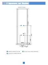
Page 19: ...With battery cabinet 4 Installing the Cabinet on a Concrete Pedestal 14 ...

Page 20: ...il engine port Nylon nuts Inner side of the cabinet door Nylon nuts Cable through components Outer side of the cabinet door Put away the removed nylon nuts among which 3 are used to fasten the cable through ring 4 Installing the Cabinet on a Concrete Pedestal 15 ...

Page 21: ...height using spacers 16 Prevent the battery cabinet from falling when hoisting it The accessories of a battery cabinet include 3 types of spacers These 3 types of spacers have different thicknesses You need to select suitable spacers based on the live network conditions to adjust the steps between cabinets that are installed side by side After the adjustment tighten the nuts 4 Installing the Cabin...

Page 22: ...cket handle recommended length 100 mm on the socket for screw tightening Fastening the Cabinet with the Outer Installation Fastening the Cabinet with the Inner Installation Holes 17 4 Installing the Cabinet on a Concrete Pedestal ...

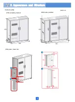
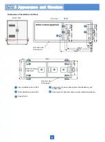
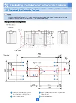
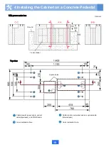
Page 23: ...18 Unit mm 4 Installing the Cabinet on a Concrete Pedestal ...

Page 24: ...m 4 Installing the Cabinet on a Concrete Pedestal With power meter box Remove the plastic fillers from the side panel of the cabinet install the supports of the cable trough Plastic fillers Cable trough support ...

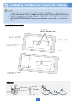
Page 25: ...20 4 Installing the Cabinet on a Concrete Pedestal ...

Page 26: ...the M6 screw to fix the power meter box to the side panel of the cabinet Use the M4 screw to fix the power meter box to the cable trough Seal the gap between the power meter box and the cabinet to prevent vapor from entering the cabinet Waterproof silicone ...

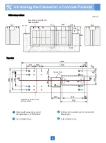
Page 27: ...22 4 Installing the Cabinet on a Concrete Pedestal ...

Page 28: ...23 5 Installing the Cabinet on an Underground Base 5 1 Appearance of the Underground Base Dimensions of the Underground Base Unit mm Top view Installation holes 4 M12 ...

Page 29: ... weight sand weight water weight Lay the concrete on the bottom of the foundation pit Reducing the ratio of water in the concrete can speed up the solidification You can reduce the ratio of water in the concrete under the condition that the concrete can be stirred thoroughly and evenly to improve the strength of the concrete before and after solidification After the concrete is solidified to some ...

Page 30: ... are pre buried use sealing materials to seal the cables or pipes outlet to prevent water intrusion Gently place the underground base on the concrete in the foundation pit and use a spirit level to level the underground base Lay 75 mm deep concrete with the same concrete ratio evenly at the bottom of the underground base Use a spirit level to level the underground base Pre bury cables pipes at the...

Page 31: ...nsure that the tramp down tool does not touch the surface of the underground base If the surface paint of the underground base is scratched repair the paint For details see the Appendix How to Repair the Paint NOTICE Pipe After the underground base is buried it rises above the ground for 300 mm The number and installation positions of pipes in the figure are for reference only and may vary with th...

Page 32: ...of back filled soil outside the base and the ground 50 mm H2 100 mm H3 height difference between the bottom of the pit and the ground 670 mm H3 730 mm Use a spirit level to check the levelness of surfaces X and Y Tramp down the back filled soil After the backfilling ensure that the soil surface does not sink when a person of 80 kg stands on it ...

Page 33: ... on the ground plan to ensure that all doors of the cabinet can be opened without difficulties The accessories of a battery compartment include 3 types of spacers These 3 types of spacers have different thicknesses Select a proper spacer based on the live network environment so that the cabinet bottom is level F01T500 cabinet Place the cabinet on the underground base Bearing capacity of the steel ...

Page 34: ...then install the 4 black plastic covers back Remove the four mounting feet of the cabinet Apply sealing materials such as silica gel and sealing mud at the holes left after the mounting feet are removed and use screw hole plugs to block the holes Fence the cabient after it is installed Waterproof silicone Screw hole plugs ...

Page 35: ... See the meter manual to connect a power meter With power meter box Remove the mechanical part from the cable aperture Remove the plastic fillers from the side panel of the cabinet install the supports of the cable trough Install the lower part of the cable trough Install the upper part of the cable trough Plastic fillers Cable trough support ...

Page 36: ...31 Install the power meter box Seal the power meter box Fence the cabient after it is installed ...

Page 37: ... and reliable in addition it is recommended to install an electrical leakage protective device on the power supply side of the site to protect personnel against the injury caused by the accidental electric shock on the device side The cross sectional area of PGND cable is 25 m 6 1 Routing the Cabinet PGND Cable ...

Page 38: ...33 With power meter box ...

Page 39: ...power supply side of the site Shut off the AC input and attach labels on the switches that will be set during the cabling work Insulate the AC terminals and all unnecessary bare parts The cross sectional area of AC power cable is not less than 10 m 6 2 Connecting Power Cables AC Power Supply Without power meter box ...

Page 40: ...35 With power meter box AC power cables AC power cables ...

Page 41: ...ct the ground cable to the ground bar of the cabinet After wiring install the protective units and short circuiting plugs on the exchange side terminal blocks for remote power supply also called protective terminal blocks and cable side terminal blocks for remote power supply also called multiplexing terminal blocks Otherwise the cabinet cannot be powered on The exchange side terminal blocks and c...

Page 42: ... details about the connections see Diagram of Cable Connections Between the RPS and MDF Lead the RPS power cable copper cable into the cabinet connect the PGND cable in the power cable to the ground bar in the cabinet and the rest of the wires to the device compartment of the cabinet Ground bar Cable side terminal block Exchange side terminal block Cable side terminal block Exchange side terminal ...

Page 43: ...en the RPS and MDF The following figure uses 2 to 1 wire pair connection as an example Install short circuiting plugs on the cable side terminal blocks and protective units on the exchange side terminal blocks Place the cover back and fasten captive screws 190 V Short circuit plug Protective unit Cable side terminal block Wires of the RPS external copper cable Wires of the RPS external copper cabl...

Page 44: ...39 6 Routing Cables 6 3 Diagram of Cable Connections Between the RPS and MDF RPS Power Supply ...

Page 45: ...er off the central office CO RPS before connecting the RPS power cable and power on the CO RPS after cable connection After routing external user cables into the cabinet reserve an extra length so as to clamp the cables to the cable side terminal block on the MDF ...

Page 46: ...ble to the ground bar of the cabinet After wiring install the protective units and short circuiting plugs on the exchange side terminal blocks for remote power supply also called protective terminal blocks and cable side terminal blocks for remote power supply also called multiplexing terminal blocks Otherwise the cabinet cannot be powered on The exchange side terminal blocks and cable side termin...

Page 47: ...r details about the connections see Diagram of Cable Connections Between the RPS and MDF Lead the RPS power cable copper cable into the cabinet connect the PGND cable in the power cable to the ground bar in the cabinet and the rest of the wires to the device compartment of the cabinet Ground bar Cable side terminal block Exchange side terminal block Cable side terminal block Exchange side terminal...

Page 48: ...een the RPS and MDF The following figure uses 2 to 1 wire pair connection as an example Install short circuiting plugs on the cable side terminal blocks and protective units on the exchange side terminal blocks Place the cover back and fasten captive screws 190 V Short circuit plug Protective unit Cable side terminal block Wires of the RPS external copper cable Wires of the RPS external copper cab...

Page 49: ...44 6 Routing Cables 6 7 Diagram of Cable Connections Between the RPS and MDF AC RPR Power Supply ...

Page 50: ...hut off the AC input and attach labels on the switches that will be set during the cabling work Insulate the AC terminals and all unnecessary bare parts The cross sectional area of AC power cable is not less than 10 m 6 6 Connecting Power Cables AC RPR Power Supply Without power meter box With power meter box AC power cables AC power cables ...

Page 51: ...46 Route the input Cables of the AC RPR power supply 6 Routing Cables ...

Page 52: ...47 Connect the monitor cable of the AC RPR power supply Cable connections when the signal transfer box is used for monitoring Cable connections when the CCU is used for monitoring 6 Routing Cables ...

Page 53: ...al Cable side terminal block Impact tool Protective unit After routing external user cables into the cabinet reserve an extra length so as to clamp the cables to the cable side terminal block on the MDF 6 8 Connecting External Subscriber Cables Copper Configuration or Optical Copper Mixed Configuration 6 Routing Cables ...

Page 54: ...49 Shielded cable ground point optional Cable side terminal block Impact tool Protective unit Scenario where fiber patching is not required such as broadband access only scenario 6 Routing Cables ...

Page 55: ...fiber must be 20 times larger than the diameter of the optical cable core or optical fiber Generally the bending radius is larger than or equal to 40 mm Only the qualified personnel are allowed to splice the optical fiber Ensure that the optical fiber is spliced according to the on site requirements and local practice Protection pipe protection pipe 50 Do not look into the optical port without eye...

Page 56: ... mm Only the qualified personnel are allowed to splice the optical fiber Ensure that the optical fiber is spliced according to the on site requirements and local practice Decide whether to deploy a fiber management tray based on site requirements Protection pipe Cable manager Without adapters on the middle panel Protection pipe All fibers must be routed over the cable manager so that the cabinet d...

Page 57: ...rotection pipe Cable manager With adapters on the middle panel Protection pipe Fiber management tray Hose clamp All fibers must be routed over the cable manager so that the cabinet door will not be hindered by protruding fibers when being closed 52 6 Routing Cables ...

Page 58: ...he optical fiber too tightly The bending radius of the optical cable core or optical fiber must be 20 times larger than the diameter of the optical cable core or optical fiber Generally the bending radius is larger than or equal to 40 mm Only the qualified personnel are allowed to splice the optical fiber Ensure that the optical fiber is spliced according to the on site requirements and local prac...

Page 59: ...tical fibers on the baffle plate of the equipment compartment All fibers must be routed over the cablemanager so that the cabinet door will not be hindered by protruding fibers when being closed Connect the other end to the device Bend radius of an optical fiber is greater than or equal to 40mm baffle plate Binding strap of the equipment compartment 54 6 Routing Cables ...

Page 60: ...All fibers must be routed over the cable manager so that the cabinet door will not be hindered by protruding fibers when being closed Fiber management tray Optical fibers of an optical cable Ground point Optical cable Protection pipe Reinforcing core Optical fibers of an optical cable 55 6 Routing Cables ...

Page 61: ... the temperature sensor of the battery compartment because the temperature sensor of the battery compartment is not needed and reserve the cable for the temperature sensor of the battery cabinet The door status sensor cable is available in 2 models The door status sensor cable delivered with the battery cabinet is of model A The model A cable needs to be replaced by a model B cable when the CCU is...

Page 62: ...Cable connections when the CCU is used for monitoring Cable connections when the signal transfer box is used for monitoring 57 6 Routing Cables ...

Page 63: ...58 Item Component Security protection system SPS CCU module Electronic lock Components of the SPS system Appearance of the CCU Layout of the CCU 43 6 220 Unit mm 442 Serial interface boards optional Main control board 7 1 Appearance and Structure ...

Page 64: ...ly to 2 GE ports with the same silkscreen on the active standby boards Need to coordinate the use of photoelectric conversion module with the code 02114632 Then connect the other end labeled as CCU FE0 FE1 of the 2 communication cables to the FE0 and FE1 ports of the CCU Use a Phillips screwdriver to tighten screws on the CCU Device compartment lock MDF compartment lock 7 Installing the Electronic...

Page 65: ... is not in position abutting the lock handle as shown in figure In this case you need to press the lock handle lever until it is in position and then swipe the access card again as shown in figure A B A B NOK Lock handle Open the cabinet door Wear the ESD wrist strap and connect its grounding end to the ESD jack on the cabinet or wear ESD gloves Remove the HW 2802 lock from the cabinet For details...

Page 66: ...e control module removed in step1 on the lock body Use a Phillips screwdriver to tighten the screws that fix the lock tongue Connect the communication terminal of the door lock to the communication cable of the CCU For details on Connections between the 3 compartment door locks and the CCU see Table 1 Verify that the cable of the electric lock does not interfere with the lock rod when the lock rod...

Page 67: ...e the electronic lock side Lock tongue CCU Port Silk Screen CCU Label Connected Component D_COM0 CCU D_COM0 Door of the device compartment D_COM1 CCU D_COM1 Door of the MDF compartment Table1 Connecting cables 7 Installing the Electronic Door Lock System ...

Page 68: ...e condensation see the related label on the cabinet front door During the power on before and after turning on each circuit breaker for the first time you must use a multimeter to check the input and output voltages and ensure that the voltages are normal normal DC voltage range 36 V DC to 72 V DC Turn off the circuit breaker of the output terminal reserved for the CCU on the DC PDB or power syste...

Page 69: ...l numbers of the electric lock cores Steps 1 and 2 are recommended steps and you can perform these 2 steps based on the site requirements Deliver the SPS security keys to the Security Department and deliver the electric lock cores to each site together with the cabinet based on the allocation rule Replace the electric lock cores at a site based on either of the following scenarios Scenario 1 If th...

Page 70: ...eft screw component and secure it on the lock handle Use a box end anti theft wrench to anti clockwise fasten the screw on the anti theft screw component Lock the cabinet door Verify that the cables of the electric lock do not interfere with the lock rod when the lock rod moves ...

Page 71: ...cified in engineering documents Check the installation position 5 The ELU port is connected correctly Check the port connection 6 The door locks are correctly installed and cables are correctly connected Check the door locks and their connections 7 Monitoring cables and AC power cables are not bundled together and the cables are neatly and securely routed Check cable routing 8 All power cables mus...

Page 72: ...package container Do not use together batteries of different types specifications capacities and batches in a group Before powering on the batteries perform the pre installation check Install the batteries according to the field installation environment If the cabinet is powered on within the day when it is installed place the batteries into the battery compartment and connect them If the cabinet ...

Page 73: ...riod since the last charging If the batteries are stored overtime make a record and consult professional personnel for processing Perform the following operations by referring to Maintenance Guide of Outdoor Cabinets If the storage period of the batteries is 8 12 months recharge the batteries If the storage period of the batteries is 12 18 months activate the batteries Battery usability check A ba...

Page 74: ...eries and the power system must be firm and correct Keep a space of at least 10 mm between batteries for heat dissipation After the batteries are installed the battery parameters must be configured during software commissioning Otherwise the battery life may be shortened Secure the battery cable to the positive and negative terminals according to the torque required by the battery vendor The cabin...

Page 75: ...es Serially connect the batteries using battery cables according to the following figure With battery cabinet Mechanical part for positioning batteries Power system 8 Installing Batteries AC Power Supply Place the battery in the battery compartment ...

Page 76: ...the battery cable in the battery cabinet Place the battery whose positive terminal is not connected with any battery cable at this position Connect this cable to the positive terminal of the battery at position A Place the batteries by the left and right positioning bars in the battery cabinet Place the batteries to the battery cabinet and battery compartment connect the battery cable at position ...

Page 77: ...72 8 Installing Batteries AC Power Supply Serially connect the batteries using battery cables according to the following figure ...

Page 78: ... in the middle or scratch on the skin Observe 10 The cross sectional area of the power cable and that of the ground cable comply with the project file satisfying the power distribution requirements of the cabinet Observe 11 Optical fiber headers and board optical ports to be used are protected with protective caps If necessary clean them in compliance with Huawei regulations Observe 12 Cables outs...

Page 79: ...on the cabinet front door During the power on before and after turning on each circuit breaker for the first time you must use a multimeter to check the input and output voltages and ensure that the voltages are normal AC ranges 200 V AC to 240 V AC DC range 42 V DC to 58 V DC After installing the cabinet and powering on the device ensure that the battery switch is in the ON state If the device ne...

Page 80: ...e safety before powering on the device check whether condensation exists in the cabinet Power on the device only after you ensure that no condensation exists For the detailed method of removing condensation see the corresponding label on the cabinet front door Green on for 1s and off for 1s repeatedly LED for fan tray Green on ...

Page 81: ...ays after installation To ensure the safety before powering on the device check whether condensation exists in the cabinet Power on the device only after you ensure that no condensation exists For the detailed method of removing condensation see the corresponding label on the cabinet front door ...

Page 82: ...s only when the device is powered on next time After cables are led in to the MDF compartment seal the cable holes by tightening the strings of the cable sealing bags 4 PCS The cabinet base that contacts with the concrete pedestal must be sealed to prevent moisture air from entering the cabinet Cover the sealing mud onto the cable hole at the bottom of the cabinet to seal the cable hole gap and th...

Page 83: ...14 FAQs for Installation 78 ...

Page 84: ...15 FAQs for Installation 79 ...

Page 85: ...n The paint coating should be thin and even Paint drops are prohibited on the coating The surface should be smooth The color of the re painted spot should be the same as the original color of the cabinet There is no visible chromatic aberration bulge or peeling paint Anhydrous alcohol Choose a suitable paintbrush based on the base color Shake up the paint before painting Dip the paintbrush into th...

Reviews: