Huawei EMU, User Manual
The Huawei EMU User Manual is your go-to resource for complete guidance on operating your Huawei EMU device. Download this comprehensive manual for free from manualshive.com to discover everything you need to know about your Huawei EMU, ensuring a seamless user experience.
Share
Download


Reviews:
No comments
Related manuals for EMU
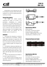
DM-50
Brand: GATT AUDIO Pages: 2
ICON
Brand: Earthworks Audio Pages: 3

LM10
Brand: Samson Pages: 24
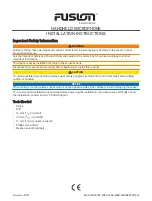
FUSION
Brand: Garmin Pages: 8
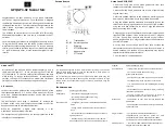
GP3
Brand: IASUS Pages: 2
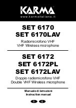
6170
Brand: Karma Pages: 12
AG-MC15P
Brand: Panasonic Pages: 12
WV-SMR10
Brand: Panasonic Pages: 20
Q1
Brand: Samson Pages: 4
P30
Brand: Earthworks Pages: 2
TC25
Brand: Earthworks Pages: 2
SMART
Brand: Hama Pages: 78
Net Mic
Brand: 2N Pages: 4
BM100
Brand: Uniden Pages: 2
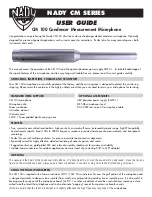
CM 100
Brand: Nady Systems Pages: 2
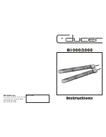
B1000
Brand: C-ducer Pages: 4
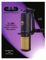
E-200
Brand: CAD Pages: 4
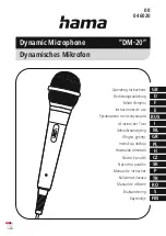
DM-20
Brand: Hama Pages: 38


