HP-00007-01, Appendix 3 30-Jun-2005
HP Restricted
Page 1
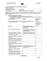
Appendix 3 Product End-of-Life Disassembly instructions
Product Identification:
Marketing Name / Model
Description
RPOS/RP5000
Small Form Factor, ATX, Point-of-Sale
Purpose:
The document is intended for use by end-of-life recyclers or treatment facilities. It provides the
basic instructions for the disassembly of HP products to remove components and materials requiring
selective treatment.
1.0
Items Requiring Selective Treatment
1.1
Items listed below are classified as requiring selective treatment.
1.2
Enter the quantity of items contained within the product which require selective treatment in
the right column, as applicable.
Item Description
Notes
Qty items in
product.
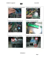
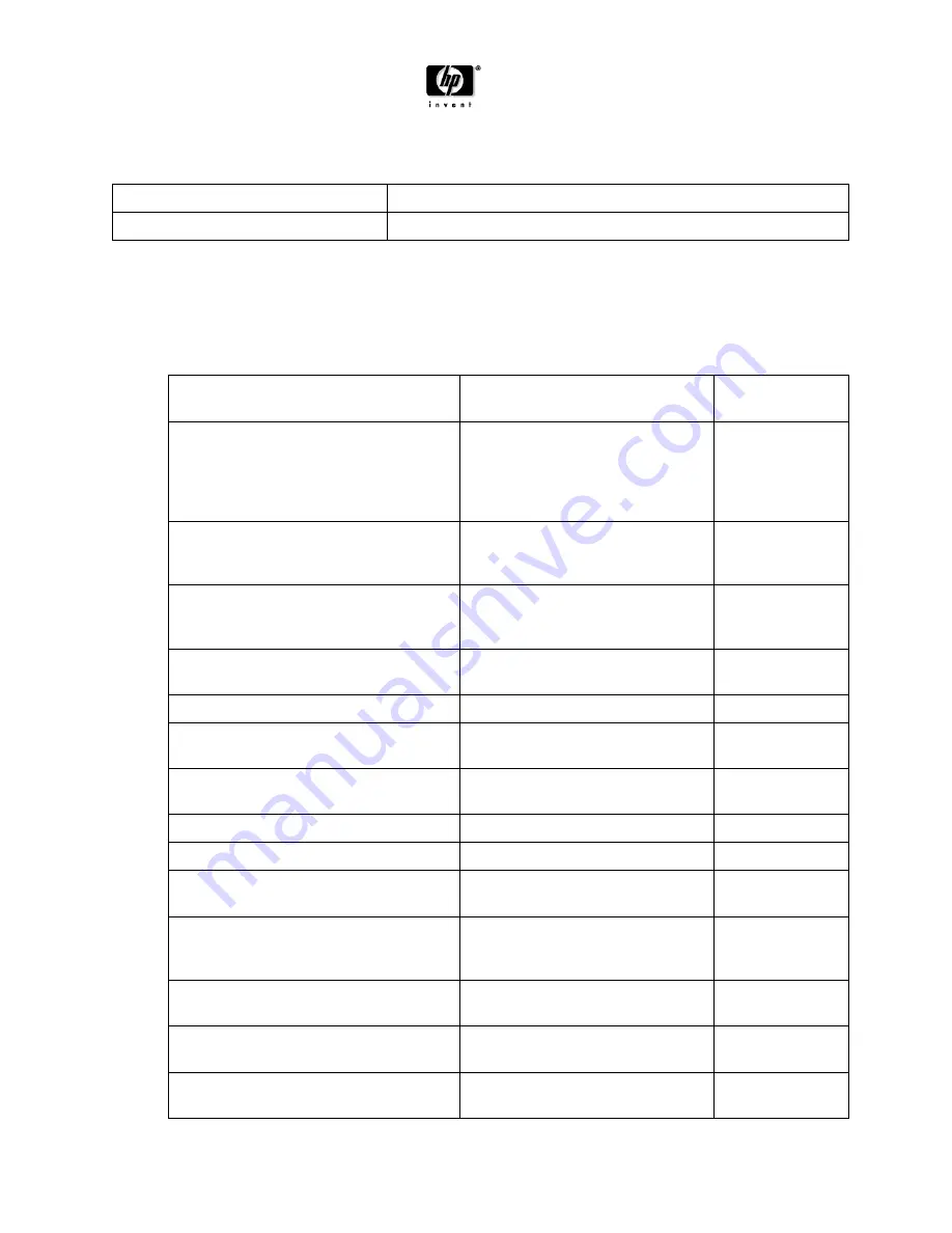
Printed Circuit Boards (PCB) or Printed
Circuit Assemblies (PCA)
With a surface greater than 10
square cm
4 PCS
- system bd
- pwr supply bd
- USB+Power bd
- riser card
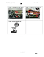
Batteries
All types including standard
alkaline and lithium coin or button
style batteries
1 PCS
Mercury containing components
For example, mercury in lamps,
display backlights, scanner lamps,
switches, batteries
0
Liquid Crystal Displays (LCD) with a
surface greater than 100 square cm
Includes background illuminated
displays with gas discharge lamps
0
Cathode Ray Tubes (CRT)
0
Capacitors / condensers (Containing
PCB / PCT)
0
Electrolytic Capacitors / Condensers
greater than 2.5 cm in diameter or hght
0
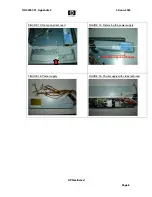
External electrical cables and cords
0
Gas Discharge Lamps
0
Plastics containing Brominated Flame
Retardants
0
Components and parts containing toner
and ink, including liquids, semi-liquids
(gel/paste) and toner
Include the cartridges, print
heads, tubes, vent chambers, and
service stations.
0
Components & waste containing
asbestos
0
Components, parts and materials
containing refractory ceramic fibers
0
Components, parts and materials
containing radioactive substances
0