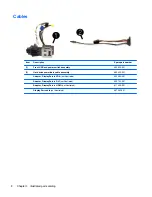
HP RP3, Maintenance And Service Manual
"Get the most out of your HP RP3 with our comprehensive Maintenance and Service Manual. This invaluable manual provides step-by-step instructions for troubleshooting, maintenance, and repair, ensuring optimal performance of your device. Visit our website today to download this manual for free and unlock the full potential of your HP RP3."
Share
Download


Reviews:
No comments
Related manuals for RP3
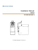
MS500
Brand: Nautilus Hyosung Pages: 23

110 Series
Brand: Sam4s Pages: 106
Class 500
Brand: National Cash Register Pages: 22
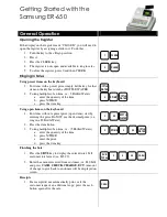
ER-650
Brand: Samsung Pages: 3
ER-290
Brand: Samsung Pages: 66
ER-265
Brand: Sam4s Pages: 106
ER-150
Brand: Samsung Pages: 2

ER-260 SERIES
Brand: Sam4s Pages: 109
ER-390 SERIES
Brand: Sam4s Pages: 206
J3500E
Brand: JCM Pages: 20

WBA Series
Brand: JCM Pages: 92

7448 Workstation
Brand: NCR Pages: 61
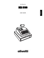
ECR 8100
Brand: Olivetti Pages: 70
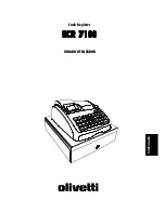
ECR 7100
Brand: Olivetti Pages: 2
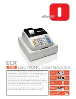
ECR 7100
Brand: Olivetti Pages: 31

ECR 7700
Brand: Olivetti Pages: 38
ECR 6900
Brand: Olivetti Pages: 50

ECR 5500
Brand: Olivetti Pages: 67


