background image

LASERJET PRO MFP

Repair Manual

M521

2

Summary of Contents for LaserJet Pro M521

Page 1: ...LASERJET PRO MFP Repair Manual M521 2 ...

Page 2: ......

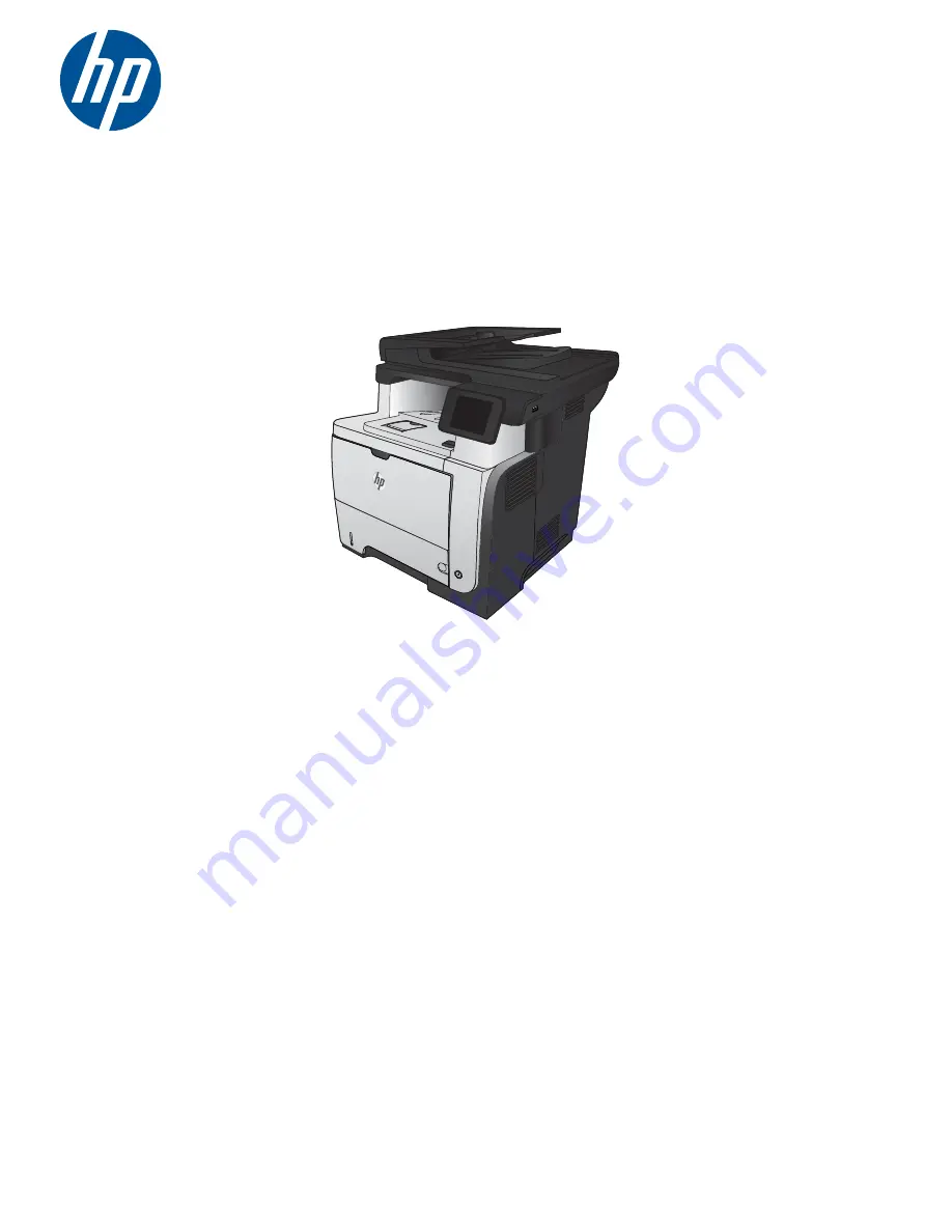
Page 3: ...HP LaserJet Pro MFP M521 Printer Repair Manual ...

Page 4: ...th in the express warranty statements accompanying such products and services Nothing herein should be construed as constituting an additional warranty HP shall not be liable for technical or editorial errors or omissions contained herein Edition 1 12 2012 Part number A8P79 90904 Trademark Credits Adobe Acrobat and PostScript are trademarks of Adobe Systems Incorporated Microsoft Windows Windows X...

Page 5: ... to explain a concept or to complete a task CAUTION Cautions indicate procedures that you should follow to avoid losing data or damaging the product WARNING Warnings alert you to specific procedures that you should follow to avoid personal injury catastrophic loss of data or extensive damage to the product ENWW iii ...

Page 6: ...iv Conventions used in this guide ENWW ...

Page 7: ...C controller connections 7 Formatter connections 9 Parts removal order 10 Removal and replacement procedures 11 Customer self repair CSR assemblies 11 Toner cartridge 11 Tray 2 or Tray 3 assembly 13 Document feeder rollers 14 Document feeder pickup roller 14 Document feeder separation roller 16 Document feeder separation pad 17 External panels covers doors and formatter 18 Formatter cover 18 Forma...

Page 8: ...g cable 64 Wi Fi module and cable 67 Main assemblies 71 Tray 1 pickup roller 71 Tray 1 separation pad 73 Tray 2 or Tray 3 pickup roller 74 Tray 2 or Tray 3 separation pad 76 Tray 2 or Tray 3 base plate roller assembly 76 Transfer roller 78 Fuser 80 Duplex paper feed assembly 83 Registration roller assembly 86 Power switch assembly 88 Interlock switch assembly 89 Tray sensor PCA 91 Main fan 93 Top ...

Page 9: ...s 143 Assembly locations 143 Base product no optional trays or accessories 143 Base product optional trays or accessories 144 Covers 146 Document feeder and scanner assemblies 148 Control panel and USB PCA assemblies 150 Document feeder assemblies 152 Internal assemblies 1 of 6 154 Internal assemblies 2 of 6 156 Internal assemblies 3 of 6 158 Internal assemblies 4 of 6 160 Internal assemblies 5 of...

Page 10: ...viii ENWW ...

Page 11: ...1 Removal and replacement Removal and replacement strategy Service approach Removal and replacement procedures ENWW 1 ...

Page 12: ...t circuit in a PCA Incorrectly routed or loose wire harnesses can interfere with other internal components and can become damaged or broken Frayed or pinched harness wires can be difficult to find When replacing wire harnesses always use the provided wire loops lance points or wire harness guides and retainers NOTE To install a self tapping screw first turn it counterclockwise to align it with the...

Page 13: ...ews or screw threads Figure 1 1 Phillips and Pozidriv screwdriver comparison Types of screws NOTE The illustration in this section are for reference only The screws in your product might look slightly different Illustration Description Size Part number Use Screw M3X6 0515 2908 Used to secure metal components to metal components for example a ground wire to the frame Screw M3X8 0515 4681 Screw tapp...

Page 14: ...14 mm 4 Chapter 1 Removal and replacement ENWW ...

Page 15: ...kstation or mat or use an ESD strap if one is available If an ESD workstation mat or strap is not available ground yourself by touching the sheet metal chassis before touching an ESD sensitive part Remove the toner cartridges See Toner cartridge on page 11 Remove the tray or trays See Tray 2 or Tray 3 assembly on page 13 After performing service Connect the power cable Reinstall the toner cartridg...

Page 16: ...urn 6 Print a demo page and then verify that the print quality is as expected 7 Send a print job from the host computer and then verify that the output meets expectations 8 If necessary restore any customer specified settings 9 Clean the outside of the product with a damp cloth 6 Chapter 1 Removal and replacement ENWW ...

Page 17: ...700 J2701 J2703 J2704 J2308 J2401 J2303 J2306 J2103 J2104 J2102 Item Description Item Description Item Description J2100 Not used J2302 MPT paper out sensor PS205 J2400 Fuser output sensor PS2 TH1 TH2 J2102 Fuser motor M8002 J2303 Face up sensor PS1 Output bin full sensor PS4 J2401 J2103 Main motor M8003 J2304 Environmental sensor TH3 J2700 LVPS ENWW Service approach 7 ...

Page 18: ...J2701 LVPS J2105 Power switch SW240 J2307 Tray detection switch SW235 J2702 LVPS J2200 HVPS J2308 Main fan FM1 J2703 Cartridge door switch SW501 J2201 Paper feeder connector J2310 CST pickup solenoid SL2 J2704 Cartridge door switch SW501 J2301 CST paper out sensor PS3 J2311 MPT pickup solenoid SL1 8 Chapter 1 Removal and replacement ENWW ...

Page 19: ...X J7 POWER J27 J3 J20 SCANNER J19 J18 WIFI J17 THUMB J22 ADF MOTOR J21 ADF SCAN Item Description Item Description J3 Control panel J19 Flatbed scanner J7 Power J20 Flatbed motor J8 LAN J21 ADF Scanner J16 USB Device J22 ADF motor J17 USB J24 Snapper Fax J18 Wifi J27 Video ENWW Service approach 9 ...

Page 20: ...ray 2 3 pickup roller Power switch assy Rear cover assy Right rear cover Rear cover assy Right rear cover Rear cover assy Left cover Formatter cover Dummy cover Rear cover assy Left cover Right rear cover Tray 1 cover Cartridge door assy Interlock switch assy Tray sensor PCA Main fan DC controller Top cover Laser scanner Tag holder assy Tray 1 cover Tray 1 cover Tray 1 cover Tray 1 cover Tray 1 co...

Page 21: ...your clothing wipe it off with a dry cloth and wash clothing in cold water Hot water sets toner into fabric 1 Press the cartridge door release button and then open the cartridge door Make sure that the door is completely open Figure 1 5 Remove the toner cartridge 1 of 2 ENWW Removal and replacement procedures 11 ...

Page 22: ...he cartridge Do not expose the cartridge to strong light Cover the cartridge with a sheet of paper to protect it from light Reinstallation tip Align the toner cartridge with its slot and insert the toner cartridge until it clicks into place Figure 1 6 Remove the toner cartridge 2 of 2 12 Chapter 1 Removal and replacement ENWW ...

Page 23: ...ocedure to remove the Tray 2 or Tray 3 assembly Pull the tray straight out of the product until it stops Carefully lift up on the tray to release it and then remove the tray Figure 1 7 Remove the tray ENWW Removal and replacement procedures 13 ...

Page 24: ...lly place the product front side up so that you can see into the opening where the tray would be installed NOTE Debris can scratch or damage the back of the product Before you place the product front side up remove any debris from the work surface If possible set the product on a clean dry cloth to prevent scratching and damage 2 Open the document feeder cover Figure 1 8 Remove the document feeder...

Page 25: ...the roller out and away from the product to remove it TIP It might be easier to release the tab by using a small flat tip screwdriver Figure 1 9 Remove the document feeder pickup roller 2 of 2 ENWW Removal and replacement procedures 15 ...

Page 26: ...e document feeder cover Figure 1 10 Remove the document feeder separation roller 1 of 2 2 Release one tab and then rotate the roller out and away from the product to remove it TIP It might be easier to release the tab by using a small flat tip screwdriver Figure 1 11 Remove the document feeder separation roller 2 of 2 16 Chapter 1 Removal and replacement ENWW ...

Page 27: ...per handling problems 1 Open the document feeder cover Figure 1 12 Remove the document feeder separation pad 1 of 2 2 Press down on the document feeder separation pad to release the pad and then remove the separation pad Figure 1 13 Remove the document feeder separation pad 2 of 2 ENWW Removal and replacement procedures 17 ...

Page 28: ...ternal panels covers doors and formatter Formatter cover Slide the formatter cover toward the rear of the product to remove Figure 1 14 Remove the formatter cover 18 Chapter 1 Removal and replacement ENWW ...

Page 29: ...Disconnect 10 cables FFCs M521dw or 9 cables FFCs M521dn NOTE To locate the formatter connector locations see Formatter connections on page 9 Figure 1 15 Remove the formatter PCA 1 of 2 3 Remove five screws and then carefully remove the formatter PCA Figure 1 16 Remove the formatter PCA 2 of 2 ENWW Removal and replacement procedures 19 ...

Page 30: ...Formatter cover See Formatter cover on page 18 2 Disconnect one connector on the fax PCA Figure 1 17 Remove the fax PCA and cable 1 of 2 3 Remove four screws and then remove the fax PCA from the product Figure 1 18 Remove the fax PCA and cable 2 of 2 20 Chapter 1 Removal and replacement ENWW ...

Page 31: ...connect board ICB 1 Disconnect two FFCs and two connectors Figure 1 19 Remove the ICB 1 of 2 2 Remove two screws Figure 1 20 Remove the ICB 2 of 2 3 Remove the ICB ENWW Removal and replacement procedures 21 ...

Page 32: ...atter PCA See Formatter PCA on page 19 Fax PCA and cable See Fax PCA and cable on page 20 ICB See Interconnect board ICB on page 21 2 Remove five screws holding the formatter stay to the chassis Figure 1 21 Remove the formatter stay 1 of 1 3 Remove the formatter stay 22 Chapter 1 Removal and replacement ENWW ...

Page 33: ...e one screw callout 1 and release one tab callout 2 Figure 1 22 Remove the dummy cover 1 of 2 2 1 Reinstallation tip Disconnect the control panel cable from the formatter to provide additional access to the tab 3 Remove the dummy cover Figure 1 23 Remove the dummy cover 2 of 2 ENWW Removal and replacement procedures 23 ...

Page 34: ...the rear door Figure 1 24 Remove the rear cover assembly 1 of 8 2 Gently pull down on the door and lower the door until it is fully open Figure 1 25 Remove the rear cover assembly 2 of 8 24 Chapter 1 Removal and replacement ENWW ...

Page 35: ...m snap back toward the product when you release it Figure 1 26 Remove the rear cover assembly 3 of 8 4 Remove two screws NOTE These two screws are of different types Make sure to install them in the correct location Figure 1 27 Remove the rear cover assembly 4 of 8 ENWW Removal and replacement procedures 25 ...

Page 36: ...rear door and then release one tab callout 1 Figure 1 28 Remove the rear cover assembly 5 of 8 1 6 Release one tab callout 1 Figure 1 29 Remove the rear cover assembly 6 of 8 1 26 Chapter 1 Removal and replacement ENWW ...

Page 37: ...er assembly 7 of 8 8 Pull down on the rear cover assembly to remove it Figure 1 31 Remove the rear cover assembly 8 of 8 Reinstallation tip Insert the top of the cover first to make sure the tabs are in place and then rotate the bottom of the cover into place ENWW Removal and replacement procedures 27 ...

Page 38: ...r 1 Before proceeding remove the following Rear cover assembly See Rear cover assembly on page 24 2 Remove one screw callout 1 Figure 1 32 Remove the left cover 1 of 3 1 28 Chapter 1 Removal and replacement ENWW ...

Page 39: ... rail It might be easier to slightly lift up the left side of the product and use a small flat tip screwdriver to release this tab Figure 1 33 Remove the left cover 2 of 3 1 2 3 4 Rotate the rear of the cover slightly away from the product and then slide the cover toward the front of the product to remove it Figure 1 34 Remove the left cover 2 of 3 Reinstallation tip Align the tabs on the front of...

Page 40: ...over assembly on page 24 2 Slide the right rear cover toward the inside of the product to release it Figure 1 35 Remove the right rear cover 1 of 2 3 Rotate the bottom of the cover away from the product and then pull down on the cover to remove it Figure 1 36 Remove the right rear cover 2 of 2 30 Chapter 1 Removal and replacement ENWW ...

Page 41: ...Reinstall the right rear cover Make sure to slide the tab on the top of the cover under the sheet metal clip Figure 1 37 Reinstall the right rear cover ENWW Removal and replacement procedures 31 ...

Page 42: ... 2 Carefully release two retaining arms callout 1 Figure 1 38 Remove Tray 1 cover 1 of 3 1 3 Slightly lift the cover to a 45 degree angle and then slide it toward the left side of the product TIP If you lower the tray too far it will not slide off of the hinge pins Figure 1 39 Remove Tray 1 cover 2 of 3 32 Chapter 1 Removal and replacement ENWW ...

Page 43: ...4 Remove the Tray 1 cover Figure 1 40 Remove Tray 1 cover 3 of 3 ENWW Removal and replacement procedures 33 ...

Page 44: ... 28 Tray 1 cover See Tray 1 cover on page 32 TIP The cartridge door assembly can be removed without removing the Tray 1 cover However it is easier to remove and reinstall the door assembly when the Tray 1 cover is not installed 2 Remove one spring callout 1 Figure 1 41 Remove the cartridge door assembly 1 of 3 1 34 Chapter 1 Removal and replacement ENWW ...

Page 45: ... damage it Figure 1 42 Remove the cartridge door assembly 2 of 3 1 4 After releasing from the hinge pins move the cartridge door to the right to release the pressure on the link arm Rotate the assembly down and then separate the link arm callout 1 from the assembly Remove the cartridge door assembly Figure 1 43 Remove the cartridge door assembly 3 of 3 1 ENWW Removal and replacement procedures 35 ...

Page 46: ... assembly on page 24 Left cover See Left cover on page 28 Document feeder scanner assembly See Document feeder scanner assembly on page 46 Tray 1 cover See Tray 1 cover on page 32 Cartridge door assembly See Cartridge door assembly on page 34 2 Remove two screws on the front of the product Figure 1 44 Remove the right cover assembly 1 of 5 36 Chapter 1 Removal and replacement ENWW ...

Page 47: ...ight side of the product Figure 1 45 Remove the right cover assembly 2 of 5 4 Remove one screw from the upper right side of the product Figure 1 46 Remove the right cover assembly 3 of 5 ENWW Removal and replacement procedures 37 ...

Page 48: ...oduct Do not dislodge the power switch assembly when you rotate the cover assembly away from the product Figure 1 47 Remove the right cover assembly 4 of 5 6 If necessary remove two screws callout 1 release two tabs callout 2 and then slide the front right cover toward the top of the right side cover to release it Figure 1 48 Remove the right cover assembly 5 of 5 1 2 38 Chapter 1 Removal and repl...

Page 49: ... at the top The top of the cover should slide over the chassis and the lower section of the cover should slide behind the chassis Figure 1 49 Reinstall the right cover assembly correct alignment 1 of 3 Figure 1 50 Reinstall the right cover assembly incorrect alignment 2 of 3 ENWW Removal and replacement procedures 39 ...

Page 50: ...2 Make sure the two tabs are securely inserted Figure 1 51 Reinstall the right cover assembly 3 of 3 40 Chapter 1 Removal and replacement ENWW ...

Page 51: ...over assembly on page 24 Left cover See Left cover on page 28 Right rear cover See Right rear cover on page 30 Tray 1 cover See Tray 1 cover on page 32 Cartridge door assembly See Cartridge door assembly on page 34 Right cover assembly See Right cover assembly on page 36 2 Remove one screw Figure 1 52 Remove the lower right cover 1 of 3 ENWW Removal and replacement procedures 41 ...

Page 52: ...t cover callout 2 toward the front of the product and then rotate the cover away from the product Figure 1 53 Remove the lower right cover 2 of 3 1 2 4 Remove the lower right cover Figure 1 54 Remove the lower right cover 3 of 3 42 Chapter 1 Removal and replacement ENWW ...

Page 53: ... the three tabs callout 2 along the bottom of the cover Figure 1 55 Reinstall the lower right cover 1 of 2 2 1 2 Rotate the cover up to engage the tabs with the slots and then slide the cover toward the front of the product to install it Figure 1 56 Reinstall the lower right cover 2 of 2 ENWW Removal and replacement procedures 43 ...

Page 54: ...able on page 20 ICB See Interconnect board ICB on page 21 Formatter stay See Formatter stay on page 22 Rear cover assembly See Rear cover assembly on page 24 Right rear cover See Right rear cover on page 30 Right cover assembly See Right cover assembly on page 36 2 Remove three screws Figure 1 57 Remove the I O plate 1 of 2 44 Chapter 1 Removal and replacement ENWW ...

Page 55: ...ed to pull outward on the lower right cover callout 1 to release the sheet metal bracket Reinstallation tip When you reinstall the bracket make sure that the tab is engaged in the slot in the chassis callout 2 Figure 1 58 Remove the I O plate 2 of 2 1 2 ENWW Removal and replacement procedures 45 ...

Page 56: ...ee Dummy cover on page 23 Rear cover assembly See Rear cover assembly on page 24 Left cover See Left cover on page 28 2 Disconnect four FFCs the FFC holder held in place by one screw and one tab and three connectors M521dw or two connectors M521dn from the formatter PCA Figure 1 59 Remove the document feeder scanner assembly 1 if 7 46 Chapter 1 Removal and replacement ENWW ...

Page 57: ...heir retainers Figure 1 60 Remove the document feeder scanner assembly 2 of 7 4 Disconnect one screw and then remove the USB ground wire Figure 1 61 Remove the document feeder scanner assembly 3 of 7 ENWW Removal and replacement procedures 47 ...

Page 58: ... assembly 4 of 7 6 Remove one screw on the rear right side of the document feeder scanner assembly callout 1 and then remove the grounding screw on the rear left side of the document feeder scanner assembly callout 2 Figure 1 63 Remove the document feeder scanner assembly 5 of 7 2 1 48 Chapter 1 Removal and replacement ENWW ...

Page 59: ...der scanner ground screw shown still installed in this photo Figure 1 64 Remove the document feeder scanner assembly 6 of 7 8 Slide the document feeder scanner assembly back and then pull up to remove Figure 1 65 Remove the document feeder scanner assembly 7 of 7 ENWW Removal and replacement procedures 49 ...

Page 60: ...bottom of the document feeder scanner assembly with the slots on the chassis Figure 1 66 Reinstall the document feeder scanner assembly 1 of 3 2 Ensure the FFCs and cables are routed through the retainers on the right side of the product Figure 1 67 Reinstall the document feeder scanner assembly 2 of 3 50 Chapter 1 Removal and replacement ENWW ...

Page 61: ...der ground wire tuck the grounding wire to the left side so it does not interfere with reinstallation of the left cover assembly Figure 1 68 Reinstall the document feeder scanner assembly 3 of 3 ENWW Removal and replacement procedures 51 ...

Page 62: ...ced 1 Before proceeding remove the following Document feeder scanner assembly See Document feeder scanner assembly on page 46 2 Carefully place the document feeder scanner assembly upside down on a flat surface 3 Remove three screws and remove the scanner rear cover Figure 1 69 Remove the Document feeder whole unit kit and scanner whole unit kit 1 of 6 52 Chapter 1 Removal and replacement ENWW ...

Page 63: ...d FFC from the document feeder scanner assembly and remove it from the channel beneath the scanner rear cover Figure 1 70 Remove the Document feeder whole unit kit and scanner whole unit kit 2 of 6 ENWW Removal and replacement procedures 53 ...

Page 64: ... rear cover NOTE Replace the cable ties to secure the wire harness when reinstalling the document feeder scanner whole unit Figure 1 71 Remove the Document feeder whole unit kit and scanner whole unit kit 3 of 6 Figure 1 72 Remove the Document feeder whole unit kit and scanner whole unit kit 4 of 6 54 Chapter 1 Removal and replacement ENWW ...

Page 65: ...ire harness through the slot in the scanner assembly to separate the document feeder assembly from the scanner assembly Figure 1 74 Remove the Document feeder whole unit kit and scanner whole unit kit 6 of 6 Document feeder assembly and scanner assembly reinstallation tips 1 Install new cable ties for the wire harness 2 Fit the ferrite core into its slot callout 1 route the wire harness callout 2 ...

Page 66: ...3 Route the FFC callout 3 and reattach it Figure 1 75 Document feeder assembly and scanner assembly reinstallation tips 1 3 2 56 Chapter 1 Removal and replacement ENWW ...

Page 67: ...ews and the document feeder hinge assembly Figure 1 76 Remove the document feeder hinge assembly Control panel top cover 1 Release two tabs on the under side of the control panel assembly Figure 1 77 Remove the control panel top cover 1 of 2 ENWW Removal and replacement procedures 57 ...

Page 68: ...2 Lift the top cover up to remove Figure 1 78 Remove the control panel top cover 2 of 2 58 Chapter 1 Removal and replacement ENWW ...

Page 69: ...e 57 2 Press forward on the control panel sub cover and remove the sub cover Figure 1 79 Remove the control panel 1 of 3 3 Remove the ground screw and wire the screw holding the control panel to the tray and one FFC Figure 1 80 Remove the control panel 2 of 3 4 Slide the control panel assembly forward and remove ENWW Removal and replacement procedures 59 ...

Page 70: ...nd wire screw and remove the ground wire Disconnect one screw near the front of the USB PCA subassembly Figure 1 81 Remove the USB PCA 1 of 4 2 Disconnect the USB cable Figure 1 82 Remove the USB PCA 2 of 4 TIP When reinstalling the USB PCA assembly connect the USB cable before installing the grounding screw and the screw near the front of the USB PCA assembly 60 Chapter 1 Removal and replacement ...

Page 71: ...crews and then remove the USB PCA from the sheet metal bracket Figure 1 84 Remove the USB PCA 4 of 4 Control panel FFC 1 Before proceeding remove the following Document feeder scanner assembly See Document feeder assemblies and scanner on page 46 Control panel top cover See Control panel top cover on page 57 ENWW Removal and replacement procedures 61 ...

Page 72: ...parate the black adhesive attached scanner and motor FFCs and Wi Fi module cables from the scanner lower cover Figure 1 85 Remove the control panel FFC 1 of 6 3 Remove three screws from the scanner lower cover Figure 1 86 Remove the control panel FFC 2 of 6 62 Chapter 1 Removal and replacement ENWW ...

Page 73: ...ol panel FFC through the openings in the lower cover as you are removing the lower cover Figure 1 87 Remove the control panel FFC 3 of 6 5 Press forward on the control panel sub cover and then remove the sub cover Figure 1 88 Remove the control panel FFC 4 of 6 ENWW Removal and replacement procedures 63 ...

Page 74: ...move the control panel FFC from the document feeder scanner assembly Figure 1 90 Remove the control panel FFC 6 of 6 USB cable and USB grounding cable 1 Before proceeding remove the following Document feeder scanner assembly See Document feeder assemblies and scanner on page 46 64 Chapter 1 Removal and replacement ENWW ...

Page 75: ...te the black adhesive attached scanner and motor FFCs from the scanner lower cover Figure 1 91 Remove the USB cable and USB grounding cable 1 of 5 3 Remove three screws from the scanner lower cover Figure 1 92 Remove the USB cable and USB grounding cable 2 of 5 ENWW Removal and replacement procedures 65 ...

Page 76: ...nel FFC through the openings in the lower cover as you are removing the lower cover Figure 1 93 Remove the USB cable and USB grounding cable 3 of 5 5 Disconnect the USB cable connector from the USB PCA Figure 1 94 Remove the USB cable and USB grounding cable 4 of 5 66 Chapter 1 Removal and replacement ENWW ...

Page 77: ...SB cable re installation When reinstalling the USB cable align the white mark on the cable with the slot near the Wi Fi module Figure 1 96 Reinstall USB cable Wi Fi module and cable 1 Before proceeding remove the following Document feeder scanner assembly See Document feeder assemblies and scanner on page 46 ENWW Removal and replacement procedures 67 ...

Page 78: ...e black adhesive attached scanner and motor FFCs and Wi Fi module FFCs from the scanner lower cover Figure 1 97 Remove the Wi Fi module and cable 1 of 6 3 Remove three screws from the scanner lower cover Figure 1 98 Remove the USB cable and USB grounding cable 2 of 6 68 Chapter 1 Removal and replacement ENWW ...

Page 79: ...l panel FFC through the openings in the lower cover as you are removing the lower cover Figure 1 99 Remove the Wi Fi module and cable 3 of 6 5 Remove one screw and then remove the Wi Fi module mounting bracket Figure 1 100 Remove the Wi Fi module and cable 4 of 6 ENWW Removal and replacement procedures 69 ...

Page 80: ... Wi Fi module from the mounting bracket Figure 1 101 Remove the Wi Fi module and cable 5 of 6 7 Disconnect the Wi Fi cable from the Wi Fi module Figure 1 102 Remove the Wi Fi module and cable 6 of 6 70 Chapter 1 Removal and replacement ENWW ...

Page 81: ...r Skin oils deposited on the roller might cause print quality problems 1 Press the cartridge door release button and then open the cartridge door Make sure that the door is completely open Figure 1 103 Remove the Tray 1 pickup roller 1 of 2 ENWW Removal and replacement procedures 71 ...

Page 82: ...ate the roller out and away from the product to remove it TIP It might be easier to release the tabs by using a small flat tip screwdriver Figure 1 104 Remove the Tray 1 pickup roller 2 of 2 72 Chapter 1 Removal and replacement ENWW ...

Page 83: ...ms 1 Press the cartridge door release button and then open the cartridge door Make sure that the door is completely open Figure 1 105 Remove the Tray 1 separation pad 1 of 2 2 Release two tabs callout 1 and then remove the separation pad Figure 1 106 Remove the Tray 1 separation pad 2 of 2 1 ENWW Removal and replacement procedures 73 ...

Page 84: ...you can see into the opening where the tray would be installed NOTE Debris can scratch or damage the back of the product Before you place the product front side up remove any debris from the work surface If possible set the product on a clean dry cloth to prevent scratching and damage 2 Release the roller bushing rotate the busing up and then slide the bushing off of the roller shaft Figure 1 107 ...

Page 85: ...e guard when the bushing is removed Figure 1 108 Remove the Tray 2 or Tray 3 pickup roller 2 of 3 1 4 Slide the roller toward the left side of the product rotate the right end of the roller away from the product and then remove the roller assembly Figure 1 109 Remove the Tray 2 or Tray 3 pickup roller 3 of 3 ENWW Removal and replacement procedures 75 ...

Page 86: ...lems 1 Remove the tray See Tray 2 or Tray 3 assembly on page 13 2 Remove two screws callout 1 and then remove the separation pad callout 2 Figure 1 110 Remove the Tray 2 or Tray 3 separation pad 1 2 Tray 2 or Tray 3 base plate roller assembly 1 Remove the tray See Tray 2 or Tray 3 assembly on page 13 76 Chapter 1 Removal and replacement ENWW ...

Page 87: ...slide the assembly toward the outside of the product to release it Figure 1 111 Tray 2 or Tray 3 base plate roller assembly 1 of 2 2 1 3 Remove the base plate roller assembly Figure 1 112 Tray 2 or Tray 3 base plate roller assembly 2 of 2 ENWW Removal and replacement procedures 77 ...

Page 88: ...re that the door is completely open NOTE If you did not remove the toner cartridge before servicing the product remove it now Figure 1 113 Remove the transfer roller 1 of 3 2 Release two tabs callout 1 at the left end of the roller slightly lift the end of the roller up and then slide the roller callout 2 toward the left to release it Remove the roller Figure 1 114 Remove the transfer roller 2 of ...

Page 89: ...3 If necessary remove the gear the bushing and the spring and then install them on a replacement roller Figure 1 115 Remove the transfer roller 3 of 3 ENWW Removal and replacement procedures 79 ...

Page 90: ...over on page 30 2 Release two tabs callout 1 on the duplex paper feed guide and then slide the guide toward the rear of the product to remove it Reinstallation tip Make sure that both tabs snap back into place when reinstalling the duplex paper feed guide Figure 1 116 Remove the fuser 1 of 4 1 80 Chapter 1 Removal and replacement ENWW ...

Page 91: ...rs callout 1 and then release one wire harness from the retainer callout 2 Figure 1 117 Remove the fuser 2 of 4 1 2 4 Remove four screws callout 1 Figure 1 118 Remove the fuser 3 of 4 1 ENWW Removal and replacement procedures 81 ...

Page 92: ... out of the back of the product CAUTION To avoid damaging the fuser the cartridge door assembly must be closed before you remove the fuser Figure 1 119 Remove the fuser 4 of 4 82 Chapter 1 Removal and replacement ENWW ...

Page 93: ...ear cover on page 30 2 Release two tabs callout 1 on the duplex paper feed guide and then slide the guide toward the back of the product to remove it Reinstallation tip Make sure that both tabs snap back into place when reinstalling the duplex paper feed guide Figure 1 120 Remove the duplex paper feed assembly 1 of 5 1 ENWW Removal and replacement procedures 83 ...

Page 94: ...re 1 121 Remove the duplex paper feed assembly 2 of 5 1 4 Use a small flat tip screwdriver to carefully pry the sheet metal tab on the assembly away from the hinge pin to release it Figure 1 122 Remove the duplex paper feed assembly 3 of 5 84 Chapter 1 Removal and replacement ENWW ...

Page 95: ...e pin to release it Figure 1 123 Remove the duplex paper feed assembly 4 of 5 6 Pull the duplex paper feed assembly out of the back of the product Figure 1 124 Remove the duplex paper feed assembly 5 of 5 ENWW Removal and replacement procedures 85 ...

Page 96: ... Left cover on page 28 2 Unhook the clasp on the registration roller assembly gear callout 1 and then slide the gear off of the shaft Figure 1 125 Remove the registration roller assembly 1 of 3 1 3 Open the cartridge door and then remove four screws Figure 1 126 Remove the registration roller assembly 2 of 3 86 Chapter 1 Removal and replacement ENWW ...

Page 97: ...4 Lift the registration roller assembly out of the product gear end first Figure 1 127 Removing the registration roller assembly 3 of 3 ENWW Removal and replacement procedures 87 ...

Page 98: ...sembly on page 24 Left cover See Left cover on page 28 Tray 1 cover See Tray 1 cover on page 32 Cartridge door assembly See Cartridge door assembly on page 34 Right cover assembly See Right cover assembly on page 36 2 Disconnect one connector callout 1 remove one screw callout 2 and then remove the power switch assembly Figure 1 128 Remove the power switch assembly 1 of 2 1 2 88 Chapter 1 Removal ...

Page 99: ...ar cover assembly See Rear cover assembly on page 24 Left cover See Left cover on page 28 Tray 1 cover See Tray 1 cover on page 32 Cartridge door assembly See Cartridge door assembly on page 34 Right cover assembly See Right cover assembly on page 36 2 Disconnect one connector callout 1 Figure 1 129 Remove the interlock switch assembly 1 of 3 1 ENWW Removal and replacement procedures 89 ...

Page 100: ...interlock switch is still connected to the product by two wires Figure 1 130 Remove the interlock switch assembly 2 of 3 1 4 Release two tabs callout 1 and then carefully remove two wire connectors Figure 1 131 Remove the interlock switch assembly 3 of 3 1 90 Chapter 1 Removal and replacement ENWW ...

Page 101: ... 23 Rear cover assembly See Rear cover assembly on page 24 Left cover See Left cover on page 28 Tray 1 cover See Tray 1 cover on page 32 Cartridge door assembly See Cartridge door assembly on page 34 Right cover assembly See Right cover assembly on page 36 2 Disconnect one connector Figure 1 132 Remove the tray sensor PCA 1 of 3 ENWW Removal and replacement procedures 91 ...

Page 102: ...3 Release one tab Figure 1 133 Remove the tray sensor PCA 2 of 3 4 Remove the PCA Figure 1 134 Remove the tray sensor PCA 3 of 3 92 Chapter 1 Removal and replacement ENWW ...

Page 103: ...Rear cover assembly on page 24 Left cover See Left cover on page 28 Tray 1 cover See Tray 1 cover on page 32 Cartridge door assembly See Cartridge door assembly on page 34 Right cover assembly See Right cover assembly on page 36 2 Disconnect one connector and then release the wire harnesses from the retainers Figure 1 135 Remove the main fan 1 of 3 ENWW Removal and replacement procedures 93 ...

Page 104: ...he air must flow into the product Make sure that the label side of the fan is toward the inside of the product when the fan is reinstalled Figure 1 136 Remove the main fan 2 of 3 1 2 4 To remove the main fan and fan duct Remove one self tapping screw callout 1 and one metal screw callout 2 and then remove the main fan and fan duct together Figure 1 137 Remove the main fan 3 of 3 1 2 94 Chapter 1 R...

Page 105: ...age 23 Rear cover assembly See Rear cover assembly on page 24 Left cover See Left cover on page 28 Document feeder scanner assembly See Document feeder scanner assembly on page 46 2 From the right side of the product remove two self tapping screws Figure 1 138 Remove the top cover 1 of 4 ENWW Removal and replacement procedures 95 ...

Page 106: ...f the product remove two self tapping screws Figure 1 139 Remove the top cover 2 of 4 4 Separate each side of the top cover from the chassis Figure 1 140 Remove the top cover 3 of 4 96 Chapter 1 Removal and replacement ENWW ...

Page 107: ...e front of the cover callout 2 to remove Figure 1 141 Remove the top cover 4 of 4 1 2 Reinstall the top cover Make sure the tabs on the chassis are correctly inserted into the slots on the cover Figure 1 142 Reinstall the top cover ENWW Removal and replacement procedures 97 ...

Page 108: ...ssembly See Rear cover assembly on page 24 Left cover See Left cover on page 28 Document feeder scanner assembly See Document feeder scanner assembly on page 46 Top cover See Top cover on page 95 2 Release one tab callout 1 on the air duct and then lift the air duct callout 2 out of the product Figure 1 143 Remove the laser scanner 1 of 5 1 2 98 Chapter 1 Removal and replacement ENWW ...

Page 109: ...allout 1 and one FFC callout 2 Reinstallation tip Make sure that you correctly reconnect the FFC when the laser scanner is installed If the FFC is not correctly reconnected a 51 1 ERROR will appear on the control panel display Figure 1 145 Remove the laser scanner 3 of 5 1 2 ENWW Removal and replacement procedures 99 ...

Page 110: ...e four screws callout 1 Figure 1 146 Remove the laser scanner 4 of 5 1 6 Lift the laser scanner up and out of the product Figure 1 147 Remove the laser scanner 5 of 5 100 Chapter 1 Removal and replacement ENWW ...

Page 111: ...on page 28 Document feeder scanner assembly See Document feeder scanner assembly on page 46 Top cover See Top cover on page 95 2 Disconnect one connector callout 1 remove one screw callout 2 and release one tab callout 3 Release the wire harness callout 4 from its holders and the DC controller and then remove the tag holder assembly Figure 1 148 Remove the tag holder assembly 1 3 2 4 ENWW Removal ...

Page 112: ... 1 cover See Tray 1 cover on page 32 Cartridge door assembly See Cartridge door assembly on page 34 Right cover assembly See Right cover assembly on page 36 Lower right cover See Lower right cover on page 41 2 Disconnect 17 connectors and three FFCs NOTE One connector callout 1 remains empty NOTE To locate DC controller connector locations see DC controller connections on page 7 Figure 1 149 Remov...

Page 113: ...ck switch assembly TIP It might be easier to release these connectors by first removing the interlock switch See Interlock switch assembly on page 89 Figure 1 150 Remove the DC controller 2 of 6 Figure 1 151 Remove the DC controller 3 of 6 ENWW Removal and replacement procedures 103 ...

Page 114: ...re 1 152 Remove the DC controller 4 of 6 5 DC controller and sheet metal plate Do the following a Remove two screws callout 1 and then remove the fan and duct assembly callout 2 Figure 1 153 Remove the DC controller 5 of 6 1 2 104 Chapter 1 Removal and replacement ENWW ...

Page 115: ...b Remove two screws callout 1 and then remove the PCA and sheet metal plate Figure 1 154 Remove the DC controller 6 of 6 1 ENWW Removal and replacement procedures 105 ...

Page 116: ...e Left cover on page 28 Right rear cover See Right rear cover on page 30 Tray 1 cover See Tray 1 cover on page 32 Cartridge door assembly See Cartridge door assembly on page 34 Right cover assembly See Right cover assembly on page 36 Lower right cover See Lower right cover on page 41 Document feeder scanner assembly See Document feeder scanner assembly on page 46 Top cover See Top cover on page 95...

Page 117: ... metal bracket callout 3 TIP If the wire harness holder callout 2 becomes dislodged replace it as shown below Figure 1 156 Remove the LVPS 2 of 10 1 3 2 4 Remove two screws and the plastic retainer Figure 1 157 Remove the LVPS 3 of 10 ENWW Removal and replacement procedures 107 ...

Page 118: ...10 6 Remove the main fan See Main fan on page 93 7 Disconnect eight connectors and two FFCs from the DC controller NOTE To locate DC controller connector locations see DC controller connections on page 7 Figure 1 159 Remove the LVPS 5 of 10 108 Chapter 1 Removal and replacement ENWW ...

Page 119: ...re harness from the holders Figure 1 160 Remove the LVPS 6 of 10 9 Remove six screws callout 1 and disconnect one connector callout 2 Figure 1 161 Remove the LVPS 7 of 10 2 1 ENWW Removal and replacement procedures 109 ...

Page 120: ...f 8 11 Tip the LVPS away from the product callout 1 and then disconnect one FFC callout 2 Figure 1 163 Remove the LVPS 9 of 10 2 1 Reinstallation tip Make sure to reconnect the FFC A 51 error will occur if it is not connected 110 Chapter 1 Removal and replacement ENWW ...

Page 121: ...VPS The black plastic cap can become dislodged when removing the LVPS Reattach the cap before reinstalling the assembly NOTE Be sure to reconnect the FFC A 51 error will occur if it is not connected Figure 1 165 Reinstall the LVPS ENWW Removal and replacement procedures 111 ...

Page 122: ...r on page 32 Right cover assembly See Right cover assembly on page 36 Cartridge door assembly See Cartridge door assembly on page 34 Lower right cover See Lower right cover on page 41 Document feeder scanner assembly See Document feeder scanner assembly on page 46 Duplex paper feed assembly See Duplex paper feed assembly on page 83 Top cover See Top cover on page 95 DC controller See DC controller...

Page 123: ...ily be dislodged if the cover is removed at this time Figure 1 166 Remove the Tray 2 paper pickup assembly 1 of 10 3 Remove one screw callout 1 and then remove the base plate callout 2 Reinstallation tip Be sure to correctly align the base plate It should match the base plate at the rear of the product Figure 1 167 Remove the Tray 2 paper pickup assembly 2 of 10 2 ENWW Removal and replacement proc...

Page 124: ...lly The solenoid and cable remain attached to the guide during removal Figure 1 168 Remove the Tray 2 paper pickup assembly 3 of 10 1 2 5 Remove one screw callout 1 and then remove the left side guide callout 2 Figure 1 169 Remove the Tray 2 paper pickup assembly 4 of 10 1 2 114 Chapter 1 Removal and replacement ENWW ...

Page 125: ...he Tray 2 paper pickup assembly 5 of 10 1 2 7 Put the product on its side so that the gear cover faces up Remove three screws callout 1 and the gear cover Reinstallation tip Note the location of the FFC callout 2 and the shaft callout 3 for reinstallation Figure 1 171 Remove the Tray 2 paper pickup assembly 6 of 10 2 1 3 ENWW Removal and replacement procedures 115 ...

Page 126: ...igure 1 172 Remove the Tray 2 paper pickup assembly 7 of 10 9 Release one tab callout 1 and then remove one gear callout 2 Figure 1 173 Remove the Tray 2 paper pickup assembly 8 of 10 1 2 116 Chapter 1 Removal and replacement ENWW ...

Page 127: ...the Tray 2 paper pickup assembly Rotate the left side of the assembly away from the product first and then remove the right side of the assembly Reinstallation tip Reinstall the right side of the assembly first and then installl the left side of the assembly Figure 1 175 Remove the Tray 2 paper pickup assembly 10 of 10 ENWW Removal and replacement procedures 117 ...

Page 128: ...cover assembly on page 36 Lower right cover See Lower right cover on page 41 Document feeder scanner assembly See Document feeder scanner assembly on page 46 Top cover See Top cover on page 95 DC controller See DC controller on page 102 Low voltage power supply See Low voltage power supply LVPS on page 106 2 Carefully unwind the wire harness callout 1 from the retainer on the gear cover callout 2 ...

Page 129: ... 2 of 3 2 1 3 4 For the Tray 2 pickup solenoid Remove one screw callout 1 and then remove the solenoid callout 2 For the Tray 1 pickup solenoid Remove one screw callout 3 and then remove the solenoid callout 4 Figure 1 178 Remove the Tray 1 or Tray 2 pickup solenoid 3 of 3 6 1 3 4 5 2 TIP Thread the FFC callout 6 through the gear cover when reinstalling and make sure to reinstall the gear callout ...

Page 130: ...age 32 Cartridge door assembly See Cartridge door assembly on page 34 Right cover assembly See Right cover assembly on page 36 Lower right cover See Lower right cover on page 41 Document feeder scanner assembly See Document feeder scanner assembly on page 46 Top cover See Top cover on page 95 DC controller See DC controller on page 102 Low voltage power supply See Low voltage power supply LVPS on ...

Page 131: ...e door assembly See Cartridge door assembly on page 34 Right cover assembly See Right cover assembly on page 36 Lower right cover See Lower right cover on page 41 Document feeder scanner assembly See Document feeder scanner assembly on page 46 Top cover See Top cover on page 95 DC controller See DC controller on page 102 Low voltage power supply See Low voltage power supply LVPS on page 106 Fuser ...

Page 132: ...2 of 4 4 Release four wire harness holders from the chassis and then rotate the output bin roller assembly up to expose the pendulum assembly TIP Use needle nose pliers to release the wire harness holders Figure 1 182 Remove the pendulum assembly 3 of 4 122 Chapter 1 Removal and replacement ENWW ...

Page 133: ...5 Remove one e clip callout 1 and the assembly callout 2 Figure 1 183 Remove the pendulum assembly 4 of 4 1 2 ENWW Removal and replacement procedures 123 ...

Page 134: ... 1 cover on page 32 Cartridge door assembly See Cartridge door assembly on page 34 Right cover assembly See Right cover assembly on page 36 Lower right cover See Lower right cover on page 41 Document feeder scanner assembly See Document feeder scanner assembly on page 46 Top cover See Top cover on page 95 DC controller See DC controller on page 102 Low voltage power supply See Low voltage power su...

Page 135: ...the wire harness through the opening in the chassis callout 2 Figure 1 185 Remove the sub fan and fan duct 2 of 5 1 2 4 Release the wire harness from the retainers callout 1 Figure 1 186 Remove the sub fan and fan duct 3 of 5 1 ENWW Removal and replacement procedures 125 ...

Page 136: ...e 1 187 Remove the sub fan and fan duct 4 of 5 1 6 To remove the fan only Release the metal static clip release two tabs callout 1 and then remove the sub fan Reinstallation tip If you install a replacement sub fan the air must flow into the product Arrows embossed on the fan frame indicate air flow direction Figure 1 188 Remove the sub fan and fan duct 5 of 5 1 126 Chapter 1 Removal and replaceme...

Page 137: ...einstall the sub fan Make sure to correctly reinstall the metal static clip Figure 1 189 Reinstall the sub fan 1 of 2 Figure 1 190 Reinstall the sub fan 2 of 2 ENWW Removal and replacement procedures 127 ...

Page 138: ...artridge door assembly on page 34 Right cover assembly See Right cover assembly on page 36 Lower right cover See Lower right cover on page 41 Document feeder scanner assembly See Document feeder scanner assembly on page 46 Top cover See Top cover on page 95 DC controller and sheet metal plate See DC controller on page 102 Low voltage power supply See Low voltage power supply LVPS on page 106 2 Rel...

Page 139: ...3 Release the wire harness from the retainers callout 1 and then remove the sensor Figure 1 192 Remove the environmental sensor 2 of 2 1 ENWW Removal and replacement procedures 129 ...

Page 140: ... Tray 1 cover on page 32 Cartridge door assembly See Cartridge door assembly on page 34 Right cover assembly See Right cover assembly on page 36 Lower right cover See Lower right cover on page 41 Document feeder scanner assembly See Document feeder scanner assembly on page 46 Duplex paper feed assembly See Duplex paper feed assembly on page 83 Top cover See Top cover on page 95 DC controller and s...

Page 141: ...over are not captive and can easily be dislodged if the cover is removed Figure 1 193 Remove the HVPS 1 of 12 3 Place the product on its rear side Remove one screw and then remove the base plate callout 2 Reinstallation tip Be sure to correctly align the base plate It should match the base plate at the rear of the product Figure 1 194 Remove the HVPS 2 of 12 2 ENWW Removal and replacement procedur...

Page 142: ...e callout 2 CAUTION Use the caution The solenoid is still attached Figure 1 195 Remove the HVPS 3 of 12 1 2 5 Remove one screw callout 1 and then remove the left side guide callout 2 Figure 1 196 Remove the HVPS 4 of 12 1 2 132 Chapter 1 Removal and replacement ENWW ...

Page 143: ...197 Remove the HVPS 5 of 12 7 Remove one screw callout 1 release one tab callout 2 and then slide the guide toward the front of the product to release it Figure 1 198 Remove the HVPS 6 of 12 1 2 ENWW Removal and replacement procedures 133 ...

Page 144: ...t the sub fan and environmental sensor hang from their wire harnesses Figure 1 199 Remove the HVPS 7 of 12 2 1 9 Remove two screws callout 1 and then disconnect one connector callout 2 Figure 1 200 Remove the HVPS 8 of 12 2 1 134 Chapter 1 Removal and replacement ENWW ...

Page 145: ...g guide callout 2 CAUTION When you place the product face side up do not damage the rear door link arm on the left side of the product NOTE The positioning guide might appear to still be fastened to the product You might have to use slight force to separate it from the product Figure 1 202 Remove the HVPS 10 of 12 1 2 ENWW Removal and replacement procedures 135 ...

Page 146: ...ve the HVPS 11 of 12 2 1 13 Remove three screws callout 1 and then remove the HVPS callout 2 NOTE Disconnect three connectors and one FFC callout 3 on the HPVS as you separate the it from the product Figure 1 204 Remove the HVPS 12 of 12 2 1 3 136 Chapter 1 Removal and replacement ENWW ...

Page 147: ...install the HVPS Make sure the HVPS is installed as straight as possible and that it aligns correctly with the grounding springs Figure 1 205 Reinstall the HVPS ENWW Removal and replacement procedures 137 ...

Page 148: ...138 Chapter 1 Removal and replacement ENWW ...

Page 149: ...agrams Assembly locations Covers Document feeder and scanner assemblies Control panel and USB PCA assemblies Document feeder assemblies Internal assemblies 1 of 6 Internal assemblies 2 of 6 Internal assemblies 3 of 6 Internal assemblies 4 of 6 Internal assemblies 5 of 6 Internal assemblies 6 of 6 Input devices Alphabetical parts list Numerical parts list ENWW 139 ...

Page 150: ...220 v 6A 8121 0729 Argentina 220 v 10A 8121 0731 Korea EU generic 220 v 10A 8121 0733 Denmark 220 v 10A 8121 0734 Thailand Philippines 220 110 v 8121 0735 South America Chile Peru 220 v 10A 8121 0737 South Africa 220 v 10A 8121 0738 Switzerland 220 v 10A 8121 0739 UK Asia Pacific 220 v 10A 8121 0740 North America 110 v 13A 8121 0837 Australia New Zealand 220 v 10A 8121 0943 China 220 v 10A 8121 09...

Page 151: ...A8P80 65010 Complete 500 sheet feeder for Tray 3 includes cassette CE530 69001 ADF whole unit kit A8P79 65014 Scanner flatbed whole unit kit A8P79 65015 ADF roller maintenance kit A8P79 65001 ADF separation pad maintenance kit A8P79 65010 Fax two ports relevant kit A8P79 65019 Service PM kit CF116 67903 ENWW Order parts by authorized service providers 141 ...

Page 152: ...rvice troubleshooting manual A8P79 90906 Fasteners used in this product NOTE The screw illustrations in the following table are for reference only Screws might vary in size and appearance from those shown in this table Illustration Description Size Part number Use Screw M3X6 0515 2908 Used to secure metal components to metal components for example a ground wire to the frame Screw M3X8 0515 4681 Sc...

Page 153: ...n the product and their component parts A parts list table follows each exploded view assembly diagram Each table lists the item number the associated part number and the description of each part If a part is not listed in the table then it is not a field replacement unit FRU Assembly locations Base product no optional trays or accessories Figure 2 1 Base product no optional trays or accessories 1...

Page 154: ...al trays or accessories Figure 2 2 Base product optional trays or accessories Table 2 5 Optional 500 sheet input tray Item Description 1 Connector 2 Tray 2 or Tray 3 3 Positioning pin 144 Chapter 2 Parts and diagrams ENWW ...

Page 155: ...ENWW Assembly locations 145 ...

Page 156: ...Covers Figure 2 3 Covers A01 A02 A03 A04 A04 A05 A05 A06 A06 A06 1 2 3 4 5 6 7 8 9 10 11 146 Chapter 2 Parts and diagrams ENWW ...

Page 157: ...RC2 7675 000CN 1 4 Cover formatter RC3 1863 010CN 1 5 Door cartridge assembly RM1 8502 000CN 1 6 Cover kit Tray 1 A8P80 65010 1 7 Multipurpose lifting plate assembly RM1 6325 000CN 1 8 Cover top assembly RM1 8516 000CN 1 9 Cover left assembly RM1 8517 000CN 1 10 Cover rear assembly RM1 8518 000CN 1 11 Cover dummy RC3 1920 000CN 1 ENWW Covers 147 ...

Page 158: ...Document feeder and scanner assemblies Figure 2 4 Document feeder and scanner assemblies 1 2 3 5 4 148 Chapter 2 Parts and diagrams ENWW ...

Page 159: ...emblies Ref Description Part number Qty 1 ADF assembly A8P79 60120 1 2 Control panel assembly A8P79 60115 1 3 Scanner assembly A8P79 60121 1 4 Wi Fi module 1150 7957 1 5 Wi Fi cable A8P80 60101 1 ENWW Document feeder and scanner assemblies 149 ...

Page 160: ...Control panel and USB PCA assemblies Figure 2 5 Control panel assembly 3 1 2 4 150 Chapter 2 Parts and diagrams ENWW ...

Page 161: ...l panel assembly Ref Description Part number Qty 1 Control panel assembly A8P79 60115 1 2 Control panel FFC A8P79 60106 1 3 USB PCA CF368 60001 1 4 USB cable A8P79 60102 1 ENWW Control panel and USB PCA assemblies 151 ...

Page 162: ...Document feeder assemblies Figure 2 6 Document feeder assemblies 1 3 2 5 4 152 Chapter 2 Parts and diagrams ENWW ...

Page 163: ...roller maintenance kit A8P79 65001 1 2 ADF separation pad maintenance kit A8P79 65010 1 3 ADF assembly A8P79 60120 1 4 ADF hinge assembly left CZ271 60020 1 5 ADF hinge assembly right A8P79 60011 1 Not shown ADF whole unit kit A8P79 65014 1 ENWW Document feeder assemblies 153 ...

Page 164: ... 6 J8001 J12 J8010 J2104 J100 J1702 J2401 PS8001 J8001 J2304 A02 A14 A09 A13 A17 A16 A18 A20 A06 A27 A10 A01 A05 A04 A03 A07 A08 A28 A22 A29 A23 A19 A25 A26 A24 A21 A1 1 A1 1 A1 1 A1 1 A1 1 A1 1 A1 1 A1 1 A15 A12 3 1 2 5 4 4 6 154 Chapter 2 Parts and diagrams ENWW ...

Page 165: ...r Qty 1 Tag holder assembly RM1 8521 000CN 1 2 Laser scanner RM1 6322 000CN 1 3 Photo interrupter IC WG8 5935 000CN 1 4 Stopper bushing arm RC2 7928 000CN 2 5 Cable flat RK2 4218 000CN 1 6 Sensor environmental PCA RM1 8622 000CN 1 ENWW Internal assemblies 1 of 6 155 ...

Page 166: ...es 2 of 6 SL1 J231 1 SL2 J2310 Z TO FIGURE 104 A29 A09 A09 A09 A09 A09 A09 A09 A03 A07 A06 A06 A05 A05 A20 A10 A13 A14 A15 A16 A08 A04 A1 1 A18 A19 A17 A12 A21 A01 A02 A09 A09 A22 A23 A24 A25 A26 A27 A30 A30 A30 A28 1 2 156 Chapter 2 Parts and diagrams ENWW ...

Page 167: ...Table 2 11 Internal assemblies 2 of 6 Ref Description Part number Qty 1 Tray 1 solenoid RK2 1490 000CN 1 2 Tray 2 solenoid RK2 1492 000CN 1 ENWW Internal assemblies 2 of 6 157 ...

Page 168: ...Internal assemblies 3 of 6 Figure 2 9 Internal assemblies 3 of 6 A02 A02 A04 A12 A13 A14 A05 A03 A10 A1 1 A02 A06 A07 A09 A08 A01 1 3 5 5 6 4 8 5 2 7 158 Chapter 2 Parts and diagrams ENWW ...

Page 169: ...er multipurpose RL1 2412 000CN 1 3 Transfer lower guide assembly RM1 6315 000CN 1 4 Cassette Tray 2 RM1 8512 000CN 1 5 Base plate roller assembly RM1 6306 000CN 4 6 Roller transfer RM1 6321 000CN 1 7 Pad multipurpose separation RC2 8575 000CN 1 8 Separation holder assembly RM1 6303 000CN 1 ENWW Internal assemblies 3 of 6 159 ...

Page 170: ...ernal assemblies 4 of 6 Z FM2 J8010 PS225 J513 PS215 J507 J1610 A01 A19 A19 A06 A06 A04 A03 A05 A14 A05 A14 A14 A08 A06 A06 A06 A06 A02 A16 A17 A18 A12 A1 1 A05 A15 A07 A20 A21 A10 A09 A13 1 9 3 4 2 5 6 7 8 160 Chapter 2 Parts and diagrams ENWW ...

Page 171: ...0CN 1 3 Paper feed guide assembly RM1 6270 000CN 1 4 Position guide assembly RM1 6273 000CN 1 5 High voltage power supply HVPS PCA RM1 8519 000CN 1 6 Top sensor PCA RM1 8617 000CN 1 7 Paper width sensor PCA RM1 8618 000CN 1 8 Switch assembly RM1 8515 000CN 1 9 Pendulum service kit RM1 6598 000CN 1 ENWW Internal assemblies 4 of 6 161 ...

Page 172: ... PS3 J2301 PS205 J2302 FM1 J2308 J18 J2400 SW501 J2306 J2304 J22 A17 A13 A13 A13 A13 A13 A15 A16 A14 A13 A03 A01 A06 A18 A02 A13 A10 A10 A10 A10 A1 1 A1 1 A04 A05 A08 A12 A20 A07 A19 5 2 9 3 4 1 6 10 12 16 17 18 15 14 13 1 1 7 8 162 Chapter 2 Parts and diagrams ENWW ...

Page 173: ...witch assembly RM1 8499 000CN 1 9 Assembly cassette pick up roller Tray 2 3 pickup roller RM1 6323 000CN 1 10 Formatter standard A8P80 60001 1 10 Formatter China only A8P79 60003 1 11 2 ports stay FMTR A8P79 00015 1 12 ICB A8P79 60002 1 A01 I O Plate 2 ports A8P79 00016 1 13 Fax PCA U S CF206 60001 1 13 Fax PCA Europe CF207 60001 1 13 Fax PCA Brazil CF208 60001 1 14 Fax cable A8P79 60105 1 15 Vide...

Page 174: ...nal assemblies 6 of 6 J8007 J8002 M8002 J8002 J4 J3 J2303 J2201 J2102 PS4 J4 PS1 J3 SW 235 J2307 A15 A12 A05 A15 A15 A15 A04 A10 A07 A02 A02 A08 A14 A16 A15 A03 A11 A09 A17 A06 6 A13 A01 A01 A01 2 1 3 3 5 4 5 164 Chapter 2 Parts and diagrams ENWW ...

Page 175: ...ay sensor PCA RM1 8620 000CN 1 2 Fuser motor assembly RM1 8523 000CN 1 3 Paper delivery roller assembly RM1 6301 000CN 4 4 Face down roller assembly RM1 6311 000CN 1 5 Photo interrupter IC WG8 5935 000CN 2 6 Spring torsion RC2 8554 000CN 1 ENWW Internal assemblies 6 of 6 165 ...

Page 176: ...Input devices 500 sheet input tray Tray 3 Figure 2 13 500 sheet input tray Tray 3 1 2 3 4 166 Chapter 2 Parts and diagrams ENWW ...

Page 177: ...3 Ref Description Part number Qty 1 Optional 500 sheet tray and feeder unit CE530 69001 1 2 Base plate roller assembly RM1 6306 000CN 4 3 Separation holder assembly RM1 6303 000CN 1 4 Cassette Tray 3 RM1 6279 000CN 1 ENWW Input devices 167 ...

Page 178: ...e 153 Assembly cassette pick up roller Tray 2 3 pickup roller RM1 6323 000CN Internal assemblies 5 of 6 on page 163 Base plate roller assembly RM1 6306 000CN Internal assemblies 3 of 6 on page 159 Base plate roller assembly RM1 6306 000CN 500 sheet input tray Tray 3 on page 167 Cable flat RK2 4218 000CN Internal assemblies 1 of 6 on page 155 Cassette Tray 2 RM1 8512 000CN Internal assemblies 3 of ...

Page 179: ...0CN Internal assemblies 4 of 6 on page 161 Fax PCA Brazil CF208 60001 Internal assemblies 5 of 6 on page 163 Fax PCA Europe CF207 60001 Internal assemblies 5 of 6 on page 163 Fax PCA U S CF206 60001 Internal assemblies 5 of 6 on page 163 Fax cable A8P79 60105 Internal assemblies 5 of 6 on page 163 Ferrite core 9170 2640 Internal assemblies 5 of 6 on page 163 Formatter China only A8P79 60003 Intern...

Page 180: ... sheet input tray Tray 3 on page 167 Pad multipurpose separation RC2 8575 000CN Internal assemblies 3 of 6 on page 159 Paper delivery roller assembly RM1 6301 000CN Internal assemblies 6 of 6 on page 165 Paper feed guide assembly RM1 6270 000CN Internal assemblies 4 of 6 on page 161 Paper width sensor PCA RM1 8618 000CN Internal assemblies 4 of 6 on page 161 Pendulum service kit RM1 6598 000CN Int...

Page 181: ...Tag holder assembly RM1 8521 000CN Internal assemblies 1 of 6 on page 155 Top sensor PCA RM1 8617 000CN Internal assemblies 4 of 6 on page 161 Transfer lower guide assembly RM1 6315 000CN Internal assemblies 3 of 6 on page 159 Tray 2 paper pickup assembly RM1 8505 000CN Internal assemblies 5 of 6 on page 163 Tray sensor PCA RM1 8620 000CN Internal assemblies 6 of 6 on page 165 Tray 1 solenoid RK2 ...

Page 182: ...A8P79 60101 Power cable ICB to formatter Internal assemblies 5 of 6 on page 163 A8P79 60102 USB cable Control panel assembly on page 151 A8P79 60105 Fax cable Internal assemblies 5 of 6 on page 163 A8P79 60106 Control panel FFC Control panel assembly on page 151 A8P79 60115 Control panel assembly Document feeder and scanner assemblies on page 149 A8P79 60115 Control panel assembly Control panel as...

Page 183: ...rnal assemblies 5 of 6 on page 163 CF368 60001 USB PCA Control panel assembly on page 151 CZ271 60020 ADF hinge assembly left Document feeder assemblies on page 153 RC2 7673 000CN Cover right rear Covers on page 147 RC2 7675 000CN Cover handle right Covers on page 147 RC2 7928 000CN Stopper bushing arm Internal assemblies 1 of 6 on page 155 RC2 8554 000CN Spring torsion Internal assemblies 6 of 6 ...

Page 184: ... on page 167 RM1 6306 000CN Base plate roller assembly Internal assemblies 3 of 6 on page 159 RM1 6306 000CN Base plate roller assembly 500 sheet input tray Tray 3 on page 167 RM1 6311 000CN Face down roller assembly Internal assemblies 6 of 6 on page 165 RM1 6315 000CN Transfer lower guide assembly Internal assemblies 3 of 6 on page 159 RM1 6321 000CN Roller transfer Internal assemblies 3 of 6 on...

Page 185: ...page 147 RM1 8518 000CN Cover rear assembly Covers on page 147 RM1 8519 000CN High voltage power supply HVPS PCA Internal assemblies 4 of 6 on page 161 RM1 8521 000CN Tag holder assembly Internal assemblies 1 of 6 on page 155 RM1 8523 000CN Fuser motor assembly Internal assemblies 6 of 6 on page 165 RM1 8615 000CN DC controller PCA Internal assemblies 5 of 6 on page 163 RM1 8617 000CN Top sensor P...

Page 186: ...176 Chapter 2 Parts and diagrams ENWW ...

Page 187: ...nd cable removing 20 formatter cover removing 18 formatter PCA removing 19 fuser removing 80 fuser motor removing 120 H high voltage power supply HVPS removing 130 I interlock switch assembly removing 89 L laser scanner removing 98 left cover removing 28 location covers 146 internal assemblies 154 optional trays or accessories base product 144 low voltage power supply removing 106 M main fan remov...

Page 188: ...enoid 118 Tray 2 separation holder 76 Tray 3 base plate roller 76 Tray 3 pickup roller 14 74 Tray 3 separation holder 76 tray cassette 13 tray sensor PCA 91 USB cover 57 repair approach 5 replacing parts cautions for 2 service approach 5 right cover assembly removing 36 right handle cover removing 41 right rear cover removing 30 S screwdrivers required 3 screws part numbers 142 replacing 2 types o...

Page 189: ......

Page 190: ... 2012 Hewlett Packard Development Company L P www hp com A8P79 90904 A8P79 90904 A8P79 90904 ...

Reviews: