background image


hp server rx4610 

Service Manual 


Online Version: 1.0 

Last Updated: June  2001 

Summary of Contents for Integrity rx4610

Page 1: ...hp server rx4610 Service Manual Online Version 1 0 Last Updated June 2001 ...

Page 2: ... This document contains proprietary information that is protected by copyright All rights are reserved No part of this document may be photocopied reproduced or translated to another language without the prior written consent of Hewlett Packard Company Torx is a registered trademark of CamCar Textron Inc Hewlett Packard Company Network Server Division Technical Communications MS 45SLE 10955 Tantau...

Page 3: ...tion 9 Introduction 9 Mass Storage 9 Mass Storage Guidelines 9 Memory Guidelines 10 Accessory Board Guidelines 10 Technical Specifications 10 Environment 10 Hardware 11 Processor Memory Set 11 Connector Pinouts 14 Mini DIN PS 2 Connectors 14 Serial Port Connector 14 Parallel Port Connector 15 USB Connector 16 Video Connector Accessory Board 16 LAN Connector Accessory Board 17 Connector Pinouts and...

Page 4: ...35 Sensor Codes 35 Event Description Codes 39 BIOS Error Codes Messages 40 Beep Codes 45 Beep Codes and Interpretation 45 Types of Memory Tests 46 First Row Memory Test 46 Base Memory Test 47 Extended Memory Test 51 Memory Test Duration 53 Aborting the Memory Test 53 Setup Dialog 53 Memory Testing Error Codes Messages 54 5 Troubleshooting 56 Preventive Maintenance Procedures 56 Troubleshooting Tip...

Page 5: ... 172 mm Fans 83 Installing the 172 mm Fans 83 Hot Swapping the 120 mm Fans 84 Removing the 120 mm Fans 84 Installing the 120 mm Fans 85 Hot Swapping a Hard Drive 86 Determining Drive Status 86 Removing a Hard Disk Drive 86 Installing a Hard Disk Drive 87 Mounting a Hard Disk Drive in a Carrier 88 Hot Swapping Power Supplies 90 Determining Power Supply Status 90 Removing a Power Supply 91 Installin...

Page 6: ...ermal Dummy 106 Removing a Processor 106 Installing a CPU Thermal Dummy 107 Installing an Additional Processor 108 Firmware and Software Changes 111 Upgrading the Firmware 111 Reinstalling the NOS 111 Removing and Installing Memory Boards 111 Removing Memory Boards 111 Installing Memory Boards 112 Installing and Removing DIMMs 113 Memory Guidelines 113 Installing DIMMs 113 Removing DIMMs 114 Remov...

Page 7: ...oard 126 PCI Hot Plug LED Board 126 Removing the PCI Hot Plug LED Board 126 Installing the PCI Hot Plug LED Board 127 Legacy I O Board 128 Removing the Legacy I O Board 128 Installing the Legacy I O Board 129 Changing the Legacy I O Board Battery 131 Power Distribution Board T Docking 132 Removing the Power Distribution Board T Docking 132 Installing the Power Distribution Board T Docking 134 Inde...

Page 8: ...8 ...

Page 9: ...l information on the installation process which the end users follow All documents are needed for complete servicing information Front Panel Control and Indicators The chassis front exposes power supplies fans and the system controls and indicators Figure 1 and Table 1 provide detail on the components controls and indicators visible from the front of the chassis LCDDISPLA Y P OW ER P W R P W R A C...

Page 10: ...n lit continuously it indicates a power failure 10 Fan Fail LED amber When flashing it indicates a fan failure 11 General Fault LED amber When lit continuously it indicates a hot plug PCI fault 12 Front panel LCD Displays information about processor type and POST codes Status LEDs for SCSI Drives 13 Drive Power LED green When lit continuously it indicates the presence of the drive and power to the...

Page 11: ... details the back of the chassis while Figure 3 details the Legacy I O Panel that resides in the upper right corner of the chassis rear AC Input Power Connector PCI Add in Board Hot Plug PCI Status LED AC Input Power Connector Figure 2 Chassis Back View 1 AC Input Power Connector 2 PCI Add In Board Expansion Slots 3 Hot Plug PCI Status LEDs 4 AC Input Power Connector ...

Page 12: ...er 1 General Information 4 Figure 3 Legacy I O Panel 1 Keyboard 2 Mouse 3 Parallel Port 4 External SCSI 5 ICMB Port 2 6 ICMB Port 1 7 Video Port 8 Ethernet Port 9 USB Ports 10 Serial Port 2 11 Serial Port 1 ...

Page 13: ...dle exposed to the front of the chassis Drives can consume up to 24 watts of power and must be specified to run at a maximum ambient temperature of 40 C 104 F DVD Drive The server supports a slimline IDE DVD drive This peripheral mounts directly above the top left power bay on the front of the chassis The drive is mounted on a removable tray that facilitates system assembly and service Power Suppl...

Page 14: ...our as you face the front of the chassis However installation order for the power supplies is as shown in Figure 4 beginning with 1 and ending with 4 Thus a system with only three power supplies has an empty bay three 4 in the figure Blanks must be installed in any bays that do not have a power supply 1 3 4 2 Figure 4 Power Supply Order ...

Page 15: ...itch on the front panel 8 Verify that the power on light on the front panel is lit After a few seconds the power on self test POST begins When you press the power button on the control panel the HP Server powers up and loads the operating system The system runs a set of power on self tests POST during this process For details refer to Chapter 4 Diagnostics Powering Down the HP Server 1 Log off all...

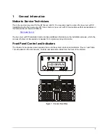
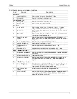
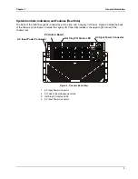
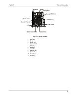
Page 16: ...Chapter 1 General Information 8 ...

Page 17: ... interface with two IDE buses The primary IDE 0 bus supports the IDE diskette drive and the secondary IDE 1 bus supports the DVD drive Refer to System Board Layout in Appendix A Specifications SCSI Device Selection A Qlogic ISP12160A Ultra3 SCSI chip is a highly integrated bus master dual channel SCSI I O processor for SCSI initiator and target applications The chip supports dual channel Ultra3 Ul...

Page 18: ...I Boards For a list of tested PCI boards check for compatibility under the Hardware Tested Products list for the HP Server rx4610 under the Service and Support topic for the specific NOS used in the server at HP s web site http www hp com CAUTION Some accessory board outputs may exceed U S National Electrical code NFPA 70 Class 2 or limited power source limits and must use appropriate inter connec...

Page 19: ... in a inch carrier One IDE diskette drive in a inch carrier Two 3 5 inch wide by 1 0 inch low voltage differential SCSI LVDS hard disk drives mounted side by side Eight 64 bit 66 MHz Hot Plug PCI I O expansion slots Two 64 bit 33 MHz Non hot Plug PCI expansions slots Cooling system Four 172 mm fans and two 120 mm fans circulate cooling air through the server The server requires a minimum of five f...

Page 20: ...port external devices This board contains all legacy I O connections and plugs into an edge connector on the I O baseboard PS 2 compatible keyboard and mouse ports PS 2 compatible parallel port The PCI enhanced Integrated Drive Electronics interface has two IDE buses supporting the diskette drive Primary IDE 0 and DVD drive Secondary IDE 1 Two universal serial bus ports Legacy I O board Two PS 2 c...

Page 21: ...0x480 200 Hz 200 Hz 200 Hz 800x600 200 Hz 200 Hz 160 Hz 1024x768 150 Hz 150 Hz 120 Hz 1152x864 120 Hz 120 Hz 85 Hz 1280x1024 100 Hz 100 Hz 85 Hz Power Supply Specifications Parameter Characteristics Input Type Auto ranging Input Maximum Range 100 to 127 VAC 5 0 A at 50 60 Hz 200 to 240 VAC 2 8 A at 50 60 Hz Operating Current 100 VAC 5 3 A 120 VAC 4 6 A 200 208 VAC 3 2 A 220 230 VAC 2 8 A In rush C...

Page 22: ...nnector Mini DIN Connector Pinouts for the Mouse and Keyboard female Pin Number Signal Description 1 Data signal 2 Not used 3 Ground 4 Power 5 V dc 5 Clock signal 6 Not used Serial Port Connector 5 4 3 2 1 9 8 7 6 Figure 6 Serial Port Connector Serial Port Connector male Pinouts Pin Number Signal Description 1 Data carrier detect 2 Receive data 3 Transmit data 4 Data term ready 5 Signal ground 6 D...

Page 23: ... Connector female Pinouts Pin Number Signal Description Pin Number Signal Description 1 Strobe5 10 Acknowledgeb 2 Data bit 0a 11 Busy 3 Data bit 1a 12 Paper end 4 Data bit 2a 13 Select 5 Data bit 3a 14 Auto line feedb 6 Data bit 4a 15 Error1 7 Data bit 5a 16 Initialize printerb 8 Data bit 6a 17 Select inb 9 Data bit 7a 18 25 Signal ground a All data bits are sent to a printer in an 8 bit parallel ...

Page 24: ...5 pin analog display pinout configuration The pinouts for your monitor may vary For the pinouts for your monitor refer to the manual provided with your monitor 1 2 3 4 5 6 7 8 9 10 11 12 13 14 15 Figure 9 Video Connector Video Connector female Pinouts Pin Number Function Pin Number Function 1 Red 9 Key no pin 2 Green 10 Sync return ground 3 Blue 11 Monitor ID bit 0 4 Monitor ID bit 2 12 Monitor ID...

Page 25: ... Information 17 LAN Connector Accessory Board 8 1 GRN LED YEL LED Figure 10 LAN Connector LAN Connector Pinouts Pin Number Signal Description 1 Data signal 2 Not used 3 Ground 4 Power 5 V dc 5 Clock signal 6 8 Not used ...

Page 26: ...reen 10 GND 3 Blue 11 NC 4 N C 12 DDCDAT 5 GND 13 HSYNC 6 GND 14 VSYNC 7 GND 15 DDCCLK 8 GND Keyboard and Mouse The PS 2 compatible connectors share a common housing but they are not functionally equivalent 3 4 6 5 2 1 Figure 12 Keyboard and Mouse Connector Pinouts Table 3 Keyboard and Mouse Connector Pinouts Pin Keyboard signal Pin Mouse signal 1 KEYDAT 1 MSEDAT 2 NC 2 NC 3 GND 3 GND 4 FUSED_VCC ...

Page 27: ...40 DB 0 7 S7 DB 1 41 S41 DB 1 8 S8 DB 2 42 S42 DB 2 9 S9 DB 3 43 S43 DB 3 10 S10 DB 4 44 S44 DB 4 11 S11 DB5 45 S45 DB 5 12 S12 DB 6 46 S46 DB 6 13 S13 DB 7 47 S47 DB 7 14 S14 DB P 48 S48 DB P 15 S15 49 S49 16 S16 DIFFSENS 50 S50 17 S17 TERMPWR 51 S51 TERMPWR 18 S18 TERMPWR 52 S52 TERMPWR 19 S19 RESERVED 53 S53 RESERVED 20 S20 54 S54 21 S21 ATN 55 S55 ATN 22 S22 S22 56 S56 23 S23 BSY 57 S57 BSY 24...

Page 28: ...ns of 1280 x 1024 and below The following table shows what is supported and what is unsupported Areas of the table that appear in gray are unsupported 2D Modes for 64 bit SDR SD SGRAM 100 MHz Buffer Memory MB 4 8 16 32 Color Depth bpp Display Mode Refresh Rate Hz 8 16 2 4 32 8 16 2 4 32 8 16 2 4 32 8 16 24 32 640 x 480 60 200 800 x 600 48 180 1024 x 768 43 140 1152 x 864 43 100 43 47 60 70 74 75 8...

Page 29: ... SGRAM 100 MHz cont Buffer Memory MB 4 8 16 32 Color Depth bpp Display Mode Refres h Rate Hz 8 16 24 32 8 16 24 32 8 16 24 32 8 16 24 32 43 60 70 72 75 85 90 100 120 1024 x 768 140 43 47 60 70 74 75 85 90 1152 x 864 100 43 47 60 70 74 75 85 90 1280 x 1024 100 ...

Page 30: ...Chapter 3 Parts Information 22 3 Parts Information Exploded View Hot Swap and Display 2 5 3 1 1 4 6 Figure 14 Hot Swap Components ...

Page 31: ...Chapter 3 Parts Information 23 Exploded View Processor Memory Access 3 Figure 15 Processor Memory Complex Access ...

Page 32: ...Chapter 3 Parts Information 24 Exploded View Processor Memory Complex 7 8 9 10 12 11 13 28 29 Figure 16 Processor Memory Complex ...

Page 33: ...Chapter 3 Parts Information 25 Exploded View Server Management Boards 13 Figure 17 Server Management Boards Exploded View ...

Page 34: ...Chapter 3 Parts Information 26 Exploded View Power Distribution Board and IDE Drives 23 24 25 26 27 30 Figure 18 T Docking Board and IDE Drives Replaceable Parts List ...

Page 35: ...e new board Ensure all jumper and switch settings on the old board are transferred to the new board Use the tables below to obtain the correct name and location of the part you need Then go to the HP PartSurfer site to order the part http outfield external hp com cgi bin spi main pl This part is not on an exploded view Parts List Identifier Figure 14 Hot Swap Components Item No Part Description 1 ...

Page 36: ...U Airflow Baffle Power Supply Filler Panel 13 3 3V D2D 28 CPU Thermal Dummy 29 CPU Board Figure 17 Server Management Boards Item No Description 14 Sideplane Board 15 5V D2D 16 Thermal Sheetmetal Kit includes D2D cover CPU Airflow Baffle Power Supply Filler Panel 17 I O Baseboard 18 External SCSI Cable 19 Legacy I O Board 20 I O Card Guide 21 Rocker Switch 22 RH AC Inlet Cable 30 Internal Power Cab...

Page 37: ...24 Power Dist Board T Dock 25 Server Mgmt Cable 26 DVD Assy 27 LS 120 Assy 12V D2D LS 120 Connector Board DVD Connector Board Hot Plug PCI Board DVD Cable LS 120 Cable HPI Cables Racking Item No Part Description Rack Kit Rail Kit Front Bezel Side Handles Kit Front Handles Kit Other Cables Item No Part Description Power Cords ...

Page 38: ......

Page 39: ...p com Quick Start Use the following steps to quickly setup and run tests For more detailed information on any of the steps refer to subsequent sections 1 Boot to the Extensible Firmware Interface EFI shell 2 Create a directory called efi intel service diagnostics on the target hard drive 3 Copy the distributed FieldDiags binary file fielddiags efi to the root directory of the target 4 Execute the ...

Page 40: ...drive If the directory does not exist refer to Installing the Diagnostic Software for instructions on how to setup the diagnostic software 3 Enter the following command to start the application fielddiags Command Syntax The field diagnostics test Command line syntax is as follows path FIELDDIAGS LOG path logfile log CFG path configfile cfg Where Items enclosed within square brackets are optional I...

Page 41: ... General User Interface The rx4610 Platform Diagnostic Tests use a single screen from which you can choose execution options enable or disable tests for execution and define test parameters The screen consists of four areas from top to bottom Execution Options Test Selection and Results Test Parameters User Interface Help The keys used to navigate the application are listed in Table 4 1 below Tabl...

Page 42: ...he arrow keys to highlight the appropriate parameter and then press the Enter key The application presents a dialog box in which you can enter the data number of loops or time in minutes Entering a zero for either parameter causes the application to ignore the parameter Running a set of selected tests always causes the application to complete at least one loop Upon completion of each loop the appl...

Page 43: ...he type command from within the EFI Shell As an alternative to renaming or moving a default log file you can use the LOG command line option when you invoke the diagnostic test software to create and place the generated log file Diagnostics Description POST The diagnostics Power On Self Test POST run automatically each time the HP Server is powered on These diagnostics which reside in the BIOS ROM...

Page 44: ...ge 07 Baseboard 1 5 Volt 08 Baseboard 1 8 Volt 0A Baseboard 2 8 Volt 0B Baseboard 3 3 Volt 0C Baseboard 3 3 Volt SB 0D Baseboard 5 Volt 0E Baseboard 5 Volt SB 0F Baseboard 12 Volt 10 Baseboard 12 Volt 11 Processor Board 1 5 Volt 12 Processor Board 1 8 Volt 13 Processor Board 3 3 Volt 15 SCSI TERM Volt 00 16 SCSI TERM Volt 01 17 SCSI TERM Volt 02 18 SCSI TERM Volt 10 19 SCSI TERM Volt 11 1A SCSI TE...

Page 45: ... right rear 1F F120 Tach Fan 5 top rear 20 F120 Tach Fan 6 top front 06 Security Violation Attempt 04 Secure Mode Violation Attempt 07 Processor 35 Processor 0 Status 36 Processor 1 Status 37 Processor 2 Status 38 Processor 3 Status 08 Power Supply 4E Power Supply 1 4F Power Supply 2 50 Power Supply 3 51 Power Supply 4 52 Upper Memory Board D2D_0 53 Upper Memory Board D2D_1 54 Lower Memory Board D...

Page 46: ...l Diag Int 15 Module Board 5D Processor Board Present 5E Upper Memory Board Present 5F Lower Memory Board Present 21 Slot Connector 39 Hot Plug PCI Slot 3 3A Hot Plug PCI Slot 4 3B Hot Plug PCI Slot 5 3C Hot Plug PCI Slot 6 3D Hot Plug PCI Slot 7 3E Hot Plug PCI Slot 8 3F Hot Plug PCI Slot 9 40 Hot Plug PCI Slot 10 23 Watchdog 03 BMC Watchdog C7 OEM C7 2B Processor 0 Fan Boost Temperature 2C Proce...

Page 47: ...sing of a threshold or the removal of a device Event Description Event Type Definition 01 N A Threshold crossed 02 N A Transition to idle active or busy 03 N A State asserted or deasserted 04 N A Predictive failure asserted or deasserted 05 N A Limit exceeded 06 1 N A Performance lag 07 1 N A Presence Disabled IERR Thermal Trip or FRB3 08 N A Device added or removed 09 N A Device enabled or disabl...

Page 48: ... Error 0117 Pri Master Drive ATAPI Incompatible 0118 Pri Slave Drive ATAPI Incompatible 0119 Sec Master Drive ATAPI Incompatible 011A Sec Slave Drive ATAPI Incompatible 011B CMOS Date Time Not Set 011E Cache Memory Error 0120 NVRAM cleared By jumper 0121 Password cleared By jumper 0141 PCI Memory Conflict 0142 PCI IO Conflict 0143 PCI IRQ Conflict 0144 Shadow of PCI ROM Failed 0145 PCI ROM not fou...

Page 49: ...s speed ratio Processor L2 cache disabled 8192 L2 cache size mismatch 8193 CPUID Processor stepping are different 8194 CPUID Processor family are different 8195 Front side bus speed mismatch System Halted 8196 CPUID Processor model are different 8300 Baseboard Management Controller failed to function 8305 Hotswap Controller failed to function 84F1 Intelligent System Monitoring Forced Shutdown 84F2...

Page 50: ...in memory subsystem Lower Board DIMM 22 8C67 Error in memory subsystem Lower Board DIMM 23 8C68 Error in memory subsystem Lower Board DIMM 24 8C69 Error in memory subsystem Lower Board DIMM 25 8C6A Error in memory subsystem Lower Board DIMM 26 8C6B Error in memory subsystem Lower Board DIMM 27 8C6C Error in memory subsystem Lower Board DIMM 28 8C6D Error in memory subsystem Lower Board DIMM 29 8C6...

Page 51: ...em Upper Board DIMM 25 8C8A Error in memory subsystem Upper Board DIMM 26 8C8B Error in memory subsystem Upper Board DIMM 27 8C8C Error in memory subsystem Upper Board DIMM 28 8C8D Error in memory subsystem Upper Board DIMM 29 8C8E Error in memory subsystem Upper Board DIMM 30 8C8F Error in memory subsystem Upper Board DIMM 31 8C90 Error in memory subsystem Upper Board DIMM 32 8C91 DIMMs mapped ou...

Page 52: ...Chapter 4 Diagnostics 44 8CA0 DIMMs mapped out Upper Board 29 32 FFFE Invalid Error Number FFFF Reached Termination during Error Processing ...

Page 53: ...ode ouccrs during system power on 1 5 5 1 CPU board interlock failure Verify CPU board inserted fully 1 5 4 2 OR 1 5 4 4 1 Power Supply Configuration Failed to retain 3 1 redundancy 1 Redundant 2 1 Processor1 Power Good failed due to power pod failure or not connected to 48V 2 2 Processor2 Power Good failed due to power pod failure or not connected to 48V 2 3 Processor3 Power Good failed due to po...

Page 54: ... 8 10 5 Lower 13 16 11 6 Lower 21 24 12 7 Lower 29 32 13 0 Lower 1 4 14 1 Lower 9 12 15 2 Lower 17 20 16 3 Lower 25 28 Upon completion of the first row memory test the memory testing continues with the base memory test If the first row test fails there are several possible failing cases Two failing scenarios are described in the following sections Case 1 The first row memory test encounters a MBE ...

Page 55: ...er Notification This memory test occurs during POST and prior to video sync Therefore any error found during this test will result in the following message displayed on the LCD panel and the system will halt First row test displayed on the upper LCD line 0064MB displayed on the lower LCD line ALL DIMM MAP OUT displayed on the upper LCD line Example 1 Consider a system that is populated with only o...

Page 56: ...his message can go by very fast Later an error message for the defective DIMM will be displayed on the video as follows 8C9X DIMMS mapped out Upper Board n n 3 Where n refers to the DIMM number Example Consider a system that is populated with two rows of 256 MB DIMMS in the upper board rows 1 4 and 5 8 If a single bit memory error was detected in DIMM 5 during the first row memory test and if no e...

Page 57: ...er LCD line RESETTING SYSTEM displayed on the lower LCD line prior to resetting if an error was found Upon reset you will see the following messages on the LCD First row test displayed on the upper LCD line 0064 MB displayed on the lower LCD line ALL DIMM MAP OUT displayed on the upper LCD line Example Consider a system is populated with two rows of 256 MB DIMMS in the upper board row 1 4 and row ...

Page 58: ...played on the lower LCD line BASE MEMORY TEST displayed on the upper LCD line ERRORS IN MEMORY displayed on the upper LCD line RESETTING SYSTEM displayed on the lower LCD line prior to resetting if an error was found Upon reset you will see the following messages on the LCD First row test displayed on the upper LCD line 0064 MB displayed on the lower LCD line BASE MEMORY TEST displayed on the uppe...

Page 59: ...ng System Event Log Intel s Server Management software specifically DPC can be used for this to determine the location of the row of defective DIMMs from the SELViewer Utility or by running either the Intel Server Control ISC or Direct Platform Control DPC to read the System Event Log SEL Replace the defective DIMMs in the example it is 5 8 On replacing the DIMMs make sure the size and HP part num...

Page 60: ...up and its final value will always be equal to the Configured line assuming all the memory is good this will be 62 GB in this example A second set of messages will be seen later in the POST which indicates where the memory test found errors The sequence is as follows Error in memory subsystem Lower Upper Board DIMM XX ERRORS FOUND IN MEMORY SUBSYSTEM FAILING ROWS WILL BE MAPPED OUT ON THE NEXT RES...

Page 61: ...rst Error Logging For the extended memory test four error records will be written for multi bit errors one for each DIMM For single bit errors during the extended memory test error records will be one per DIMM By specifications the DIMM number will be one less than the silk screened number on the printed circuit board Please refer to Error Log Format Specification Version 0 7 for details on the fo...

Page 62: ...T This may lead to data corruption and loss and HP DOES NOT RECOMMEND that this feature be disabled in the BIOS The Clear Bad Memory Row Info is used to clear the history and retest all memory This option is used when defective memory has been replaced and the user wishes to place it in service again This option automatically goes back to disabled after the next boot Memory Testing Error Codes Mes...

Page 63: ...r in memory subsystem Lower Board DIMM 30 8C6F Error in memory subsystem Lower Board DIMM 31 8C70 Error in memory subsystem Lower Board DIMM 32 8C71 Error in memory subsystem Upper Board DIMM 1 8C72 Error in memory subsystem Upper Board DIMM 2 8C73 Error in memory subsystem Upper Board DIMM 3 8C74 Error in memory subsystem Upper Board DIMM 4 8C75 Error in memory subsystem Upper Board DIMM 5 8C76 E...

Page 64: ...ard DIMM 31 8C90 Error in memory subsystem Upper Board DIMM 32 8C91 DIMMs mapped out Lower Board 1 4 8C92 DIMMs mapped out Lower Board 9 12 8C93 DIMMs mapped out Lower Board 17 20 8C94 DIMMs mapped out Lower Board 25 28 8C95 DIMMs mapped out Lower Board 5 8 8C96 DIMMs mapped out Lower Board 13 16 8C97 DIMMs mapped out Lower Board 21 24 8C98 DIMMs mapped out Lower Board 29 32 8C99 DIMMs mapped out ...

Page 65: ...g benzene trichlorethylene ammonia dilute ammonia or acetone These chemicals could damage the keyboard s plastic surfaces HP recommends the periodic cleaning of tape heads capstans and guides on HP drive units and those products using high density data cartridges and mini data cartridges This maintenance procedure prolongs tape and head life and helps reduce read write errors due to dust and oxida...

Page 66: ...m telephone ringing voltages Disconnect the power cord to avoid exposure to high energy levels that may cause burns when parts are short circuited by metal objects such as tools or jewelry 3 Simplify the HP Server configuration to the minimum required A monitor one flexible disk drive one DVD drive one hard disk drive keyboard mouse and NIC Remove all third party options and reinstall one at a tim...

Page 67: ...C DC Converter on the Power Distribution Board is properly installed 4 Check that the DC DC Converter on the I O Baseboard is plugged into the 3 3V number one connector 5 Check for a Power Pod failure on a Processor If the HP Server Powers On but then Shuts Down with a Fault Light Use this checklist to check for the following problems when the HP Server powers on and then off 1 Check that a conduc...

Page 68: ...onal c If the HP Server still is not operational turn off the monitor the HP Server and all external devices and check the internal hardware as follows i Unplug the power cord and all telephone cables ii Swap out the Legacy I O Card and reboot the HP Server iii Check that all accessory boards DC DC Converters power pods and processors are firmly seated in their slots iv Verify that the DIMMs are i...

Page 69: ... and processors are firmly seated in their slots 2 Replace the Power Pod 3 Replace the DC DC Converters If the HP Server s SCSI Drives Are Not Recognized Check the following if the SCSI drives are not recognized during POST 1 Check the seating of the Internal SCSI Cable between the I O Board and the Power Distribution Board T Docking 2 Check that the SCSI drives are enabled in the BIOS Setup If th...

Page 70: ... the updated BIOS release notes clear the CMOS for the first time Password Problems This section describes some common password problems Resetting Lost Passwords If you have forgotten the User or Administrator password you can reset each one The User password can be reset if you know the Administrator password but the Administrator password can only be reset by a switch on the system board User Pa...

Page 71: ... new Administrator password 11 Choose the Exit option and save the changes to save the new password General HP Server Problems No lights are on and no error message appears If the HP Server does not work no lights are on including backlighting on models with LCDs and no error message appears check the following 1 Verify that power is good and available 2 Make sure that the HP Server is turned on t...

Page 72: ... seconds and plug the power cords in and turn it on Verify the failure 3 If the problem persists replace the system board 4 Once a problem has been found with a part verify that it is the problem or the only problem by reinstalling the part and replicating the error The HP Server does not start boot Locate the memory modules SIMMs DIMMs NOTE The POST error messages reflect which modules are defect...

Page 73: ...erver PCBs DC power supply cables to disk drives and or mass storage cages 4 If the fans aren t audible and the above steps are verified check that power is getting to all fans Servers have multiple fans All fans run when power is turned on all are off when the power is off 5 With the power supply connected to the system board check the power supply s voltages If voltages are not present a Turn of...

Page 74: ...rify the monitor starts displaying normally 6 If the problem persists and if the power cord is detachable try a known good power cord 7 Unplug the power cord and wait 30 seconds Plug in the power cord and turn on the HP Server Wait a full 2 minutes Check that the monitor starts displaying normally 8 Check the monitor display to see if the system memory count takes place correctly a Turn the HP Ser...

Page 75: ...omputer c Check for bent pins on the connectors 15 If the customer has installed a video board instead of using the built in video make sure all jumpers and switches are set properly on the installed video board See the manual for the video board 16 If the monitor displays a badly scrambled image that looks to be the current screen image then the monitor is not synchronizing correctly If a video b...

Page 76: ...ation or the clock stops you should replace the battery or install an external battery WARNING There is a danger of explosion if the battery is incorrectly installed For your safety never attempt to recharge disassemble or burn the old battery Replace only with the same or equivalent type recommended by the manufacturer Dispose of used batteries according to the manufacturer s instructions Symptom...

Page 77: ... correct port setting when you configured the printer The printer must be configured correctly for the HP Server and for the application You may need to change some switch settings on the printer 10 Ensure you have not disabled the I O ports Run the Setup Utility press F2 during the boot process and verify the I O port status 11 Ensure the server s printer port is working properly by running anoth...

Page 78: ...a known good cable 8 If the problem persists replace the system board 9 Once a suspect part has been found verify that it is the problem by reinstalling the part and duplicating the error Symptom The mouse does not work or is intermittent The HP Server automatically detects a mouse when one is installed If the mouse or other input device is not working perform the following 1 Review the Troublesho...

Page 79: ...o a flexible disk Ensure diskette is not write protected Ensure disk drive is properly configured with the Setup utility Make sure that Start from Flexible Disk option is disabled 6 Verfiy all internal drive cables are securely attached and functional Inspect the cables and reseat the connectors at both ends 7 If the cables are securely attached and the drive still does not work replace the cables...

Page 80: ...D disk is in the DVD drive 3 Verify that all internal drive cables are securely attached and functional 4 If the drive is a Hewlett Packard DVD drive review the DVD Installation Guide for any special installation instructions 5 Try installing a known good DVD drive 6 f the problem persists check for environmental problems that can damage disk media and disk drive heads Environmental problems resul...

Page 81: ...nnected to a connector on the controller bus termination for that connector is disabled Verify that the last device on the bus is terminated 8 Ensure no device is set to SCSI ID7 this is the SCSI ID used by the SCSI controller 9 Verify all SCSI devices are either single ended or differential SCSI devices depending on the HP Server model and that any bus does not contain both types 10 Verify the SC...

Page 82: ...xternal SCSI cables 10 Check that all SCSI devices are connected to power and power on all SCSI devices before or at the same time as the HP Server to ensure a stable SCSI bus 11 Watch the boot screen for all SCSI devices to be displayed For example in a HP Server with 1 SCSI controller and 2 hard disk drives one with ID 0 and one with ID 1 if a valid device is found at device address 0 but not at...

Page 83: ... Verify that the SCSI ID and other switch settings are correct and get specific information or verification that the problem is the SCSI bus 3 If an accessory board was added recently check if there is a resource conflict between the new board and an existing accessory board Also if you have changed the options on an existing board there may be a resource conflict a Remove the new board and restar...

Page 84: ... CPU board Memory Problems The memory modules are DIMMs NOTE If the POST displayed at power on time indicates a defective memory module replace it 1 Review the Troubleshooting Checklist before you continue 2 If memory problems are being experienced power the HP Server off and on This performs a cold restart rather than a warm restart as it does when you press Ctrl Alt Del Check the System Event Lo...

Page 85: ...r cable 3 Verify there are no resource conflicts between the NIC and any other accessories in the HP Server Check the Setup Utility 4 Check the LEDs on the adapter at the back of the computer to see if any show activity No lit LEDs probably indicate a bad network cable hub connection or other network error 5 Ensure you re using the latest and correct drivers Verify the drivers are intended for thi...

Page 86: ......

Page 87: ...bladed screwdriver Jumper removal tool or needle nosed pliers Antistatic wrist strap and conductive foam pad recommended Pen or pencil Equipment log as you integrate new parts into the system add information about them to your equipment log Record the model and serial number of the system all installed options and any other pertinent information specific to the system Safety Before You Remove Serv...

Page 88: ...t in the processor memory complex Allow all fans to continue to run until they shut down on their own after power has been turned off After the fans stop the power cords can be removed CAUTION Electrostatic discharge ESD and ESD protection ESD can damage disk drives boards and other parts We recommend that you do all procedures in this chapter only at an ESD protected workstation If one is not ava...

Page 89: ...do not operate the server with the cover removed Always reinstall them before turning on the server A B C Figure 19 rx4610 Covers Rear half of the cover 120 mm fan cover Top cover Removing the Top Cover To remove the cover follow these steps 1 Turn off all peripheral devices connected to the server 2 Power down the server by pressing and holding the Power button on the Front Control Panel You may ...

Page 90: ...ou have not left loose tools or parts inside the system 3 Check that cables add in boards and other components are properly installed 4 Make sure that the 120 mm fan cover is lifted and open 5 Fold the rear part of the top cover open and set it down on the chassis aligning the hooks on both sides of the front half of the cover 6 Place your hands on the sides of the chassis near the hinge of the re...

Page 91: ...idual fan LEDs may be seen through view ports in the fan covers Removing the 172 mm Fans To remove the 172 mm fan complete the following steps 1 Observe all standard safety and ESD precautions 2 Slide the server out of the rack far enough to expose the fan access doors near the front sides of the chassis CAUTION Do not leave the door open for an extended time Cooling of the system could be reduced...

Page 92: ...thout shutting down power to the system If it is a failed fan the amber LED will be illuminated on the front panel and the amber LED on the failed fan itself will be illuminated The individual fan LEDs may be seen through view ports in the fan covers Removing the 120 mm Fans To remove the 120mm fan complete the following procedure 1 Slide the server out of the rack far enough to expose the fan acc...

Page 93: ...the top of the chassis 2 Unscrew the thumbscrew on the front of the fan access door and lift the door open 3 Slide the new fan into place with the connector oriented to engage the socket inside of the fan enclosure 4 Push the fan assembly firmly into the enclosure to seat the connector 5 Close the fan access door and tighten the thumbscrew 6 Slide the chassis back into the rack ...

Page 94: ... faulty Amber LED Right Description and Action If Required On Off Off Drive is present with power On Blinking Off Drive is present with power and is being accessed Off Off On Steady amber fault light indicates drive has a problem On Off Slow Blinking Drive SHOULD NOT be replaced at this time A slowly blinking amber fault light indicates that a drive that has just been replaced is in recovery mode ...

Page 95: ... procedure 1 Remove the plastic bezel on the front of the server 2 Orient the new drive s carrier and drive assembly in front of the bay guide rails so that the latch is toward the top Make sure that the carrier is placed correctly into the guide rails to avoid damage CAUTION Do not press on the perforated metal bracket of the carrier when you push the assembly into the bay or you may damage the m...

Page 96: ...e Record the model and serial numbers of the drive in your equipment log Orient the drive carrier so that the handle is toward your left and the metal EMI ESD fingers are toward your right Orient the drive so that both the following are true The drive s label faces away from the carrier heatsink toward the carrier fingers The drive s connector faces away from the carrier handle CAUTION Be careful ...

Page 97: ...Chapter 6 Replacing Parts 89 Figure 24 Hard Disk Carrier Figure 25 Mounting Hard Disk Drive to Carrier Assembly ...

Page 98: ...ation order 1 3 4 2 If only 3 power supplies are operational place a filler panel over the fourth bay in the installation order Figure 26 Power Supply Installation Order Determining Power Supply Status When the amber power supply failure LED on the front of the chassis turns on determine which power supply is defective by checking the three status LEDs on each supply Each power supply has three LE...

Page 99: ...tem Figure 27 Removing a Power Supply 3 Pull the power supply straight forward out of the chassis Set it aside Installing a Power Supply The power supply bay should not be vacant for more than five minutes when server power is on Disruption of the airflow may cause system cooling to fall below acceptable levels To install the new power supply complete the following procedure 1 Remove the new power...

Page 100: ...ide of the chassis 8 Release the plastic retaining mechanism I O Card Guide that secures the end of the board nearest the front of the chassis 9 Carefully grasp the adapter board and gently slide it up and out of the system Make sure that you do not scrape the board against other components 10 Store the board in an antistatic protective wrapper 11 Install an expansion slot over the vacant slot by ...

Page 101: ...ettings according to the board manufacturer s instructions See Appendix B for the equipment log form 7 Skip to step 8 if you are installing a board in an empty slot To replace a board or install a different board in an occupied slot after the LED shows which slot is powered down press the center of the PHP mechanism to disengage it from the LED board 8 Be sure that the plastic retaining mechanism ...

Page 102: ...he chassis up until it clicks into place This position both secures the end of the board and allows it to be activated with the operating system or GUI application 14 Close the rear part of the top cover and tighten the two thumbscrews 15 Connect any required cabling to the add in board 16 If your server is operating use the operating system or GUI application to power up the PCI I O slot into whi...

Page 103: ...slot hinge Access is now available to the two non hot plug PCI slots and the Legacy I O board 9 Label and disconnect all peripheral cables attached to the board you are going to remove 10 Release the plastic retaining mechanism I O Card Guide that secures the end of the board nearest the front of the chassis 11 Press the center of the rocker switch that secures the end of the board nearest the rea...

Page 104: ...umber to be used See Figure 30 PCI Hot Plug Slots Non PCI Hot Plug Slots Figure 30 Accessory Slots NOTE Refer to the Readme file for the Tested Products List that shows specific slot recommendations for a particular PCI board type 7 Lift the rear cover to expose the non hot plug PCI adapter board cover 8 Loosen the screw that secures the non hot plug PCI adapter board cover 9 Grasp the cover by it...

Page 105: ...ng careful not to touch the components or gold edge connectors on the add in board remove it from its protective wrapper and place it component side up on a nonconductive antistatic surface 14 Record the serial number of the board in your equipment log See Appendix B for the equipment log 15 Press the PCI adapter board down firmly until it seats in its slot 16 Close the plastic latching mechanism ...

Page 106: ...ont bezel 3 Remove each hard disk drive from the drive bay by first grasping its handle and depressing the drive locking tab and then sliding the drive out of the bay 4 Remove the four 2 Phillips screws from the top and bottom of the drive bay 5 Grasp the bay by the Front Panel display housing and gently pull the drive bay out of the chassis Figure 32 Hard Disk Bay Installing the Hard Disk Bay To ...

Page 107: ...nel mounting on the Hard Disk Bay These screws are located on the inside of the Front Panel Board 5 Remove the Front Panel Board from the Hard Disk Bay assembly and place it on an ESD protected work surface 1 Disconnect the cable 2 Remove the two screws Figure 33 The Front Panel Board Installing the Front Panel Board To install the new Front Panel Board complete the following steps 1 Using two Phi...

Page 108: ...e drive s data and power cables from cable adapter PCB at the rear of the drive 4 Loosen the thumbscrew found at the rear of the drive carrier assembly 5 Slide the drive and the drive carrier assembly toward the rear of the chassis so that the front part of the drive clears the opening in the chassis 6 Remove the drive carrier assembly with the drive in it from the chassis 7 Place the drive in an ...

Page 109: ...ng the HP Server s Main Cover in Chapter 2 3 Disconnect the drive s data and power cables from the drive cable adapter PCB at the rear of the drive 4 Loosen the thumbscrew found at the rear of the drive carrier assembly 5 Slide the drive and drive carrier assembly towards the rear of the chassis so that the front part of the drive clears the opening in the chassis 6 Place the drive in an antistati...

Page 110: ...oving and Replacing the HP Server s Main Cover Connecting External SCSI Devices The second SCSI channel B is connected directly to the external VHD Very High Density 68 pin SCSI connector on the rear panel All external SCSI devices are connected to the HP Server using this external connector but the external SCSI devices must provide the necessary termination at the end of the SCSI chain If no ext...

Page 111: ...ts such as tools or jewelry 2 Disconnect the power cables and any external cables connected to the system If necessary label each cable to expedite re assembly WARNING Make sure that the rack is anchored securely so that it does not tip when the server is extended from the rack 3 Pull the chassis out of the rack to expose the Processor Memory Bay on the right side of the chassis as you face its fr...

Page 112: ...assis so that they are engaged at the same time seating the Complex into the Sideplane board 4 Fasten the four screws on the left side of the chassis to hold the Processor Memory Complex in place 5 Locate the Processor Memory Complex Cover and orient it such that the right side of the cover is just to the left of the right side of the bay 6 Press the cover s edge past the chassis and slide the cov...

Page 113: ... sure that all pins face the center For partial shipments load toward the center of the clamshell Finally be sure that all locking features are fully mated along the perimeter of the clamshell Attaching a Heat Sink to a Microprocessor The Intel Itanium Processor requires a heat sink to dissipate energy The heat sink resides on top of the processor Before adding a Microprocessor to your system you ...

Page 114: ...s or CPU thermal dummies in the Processor Memory Complex To remove the baffle press the flexible retaining tabs in as you slide the baffle out You need this sheet metal baffle out of the way to access some of the captive screws in the next step 6 Loosen the captive screws in the top of the triple beam and lift it up and away from the Processor Memory Complex 7 Lift the blanks out of the complex Re...

Page 115: ...ket and remove it from the system 11 Place the cartridge on a clean ESD protective surface Installing a CPU Thermal Dummy CPU thermal dummies must be installed where a processor is absent to properly direct cooling airflow Complete the following procedure to install a CPU thermal dummy 1 Observe the safety and ESD precautions at the beginning of this chapter 2 If you are installing a CPU thermal d...

Page 116: ... 1 Unpack the processor shipping box and check the contents against its packing list 2 If the HP Server is already installed and operating shut down the NOS according to directions in your NOS documentation 3 Press the power switch on the HP Server s control panel when prompted by the operating system Normally this completes the shutdown procedure WARNING Power supplies will continue to provide st...

Page 117: ... the Processor Baseboard Ensure that the engaging tab is to the rear of the retention module RM and then slide it forward to engage its connector on the processor Figure 40 Connecting the Power Pod 11 Place the triple beam into position by lowering it down over the processors power pod or the CPU thermal dummy ...

Page 118: ...g a CPU thermal dummy skip this step Otherwise connect the Y cable to each power pod 13 Insert the sheet metal baffle at the front of the processors or CPU thermal dummies in the Processor Memory Complex To insert the baffle press the flexible retaining tabs in as you slide the baffle into place 14 Be sure to close the plastic latch to secure the Processor Memory Complex halves 15 Insert the Proce...

Page 119: ...oards exist one plugged in to each side of the processor board the top and the underside of the Processor Memory Complex The following procedure describes the removal process for either memory board To remove the memory board complete the following procedure 1 Open and remove the Processor Memory Complex 2 If desired remove the DIMMs from the memory board you are removing 3 Remove the DC DC conver...

Page 120: ...oard connector and guide pins 4 Engage both guide pins at the same time Ensure that the memory board remains parallel to the Processor Baseboard NOTE Both extraction levers must be depressed evenly while inserting the Memory Board The Memory Board must remain parallel to the Processor Baseboard during insertion 5 Slowly depress the levers until the Memory Board connector fully engages 6 Tighten th...

Page 121: ...hat the same size DIMM is used in any given row by using the same HP part number To ensure optimum performance when two boards are installed the memory on each board must be equal that is the DIMMs must be the same type and quantity Ensure both latches close on the DIMM when completely installed When handling DIMMs observe anti static precautions to avoid damage Installing DIMMs To install DIMMs c...

Page 122: ...ion Sequence 7 Insert the bottom edge of the DIMM into the socket and press down firmly until the DIMM is seated correctly 8 Push the plastic ejector levers on the socket ends to the upright position Repeat the DIMM installation steps for each DIMM you wish to install Removing DIMMs You may need to remove a DIMM module to downsize your memory configuration or to replace a defective DIMM 1 If the s...

Page 123: ...essor Memory Complex 3 Loosen the slide clamp screw that secures the converters but do not remove it Loosening the upper screw allows you to remove the upper converters while loosing the lower screw allows you to remove the lower converters 4 With the converters to be removed located on the top of the unit slide the clamp upward that secures that pair of converters 5 Pull each converter straight o...

Page 124: ...mory board beneath the complex turn the complex over and then replace the converters 6 Reinstall the Processor Memory Complex as described in Installing the Processor Memory Complex Figure 45 Memory Board DC to DC Converters Installing the Processor Baseboard The Processor Baseboard resides between the two halves of the Processor Memory Complex Removal of the Processor Baseboard involves disassemb...

Page 125: ... four to remove components and hardware from this side of the Processor Baseboard 7 With all components and hardware removed from both sides of the Processor Memory Complex carefully turn it over again so that it is oriented with its face up 8 Loosen the two captive screws securing the Processor Baseboard between the two halves of the Processor Memory Complex 9 Open the four plastic latches that s...

Page 126: ...rocessor Memory Complex over so that you can work on the underside 7 Locate and place the triple beam into position Do not install microprocessors or power pods NOTE Securing the triple beam into position without the microprocessors and power pods reduces the possibility of stress occurring on the Processor Baseboard when you install microprocessors and the memory board on the topside Secure the t...

Page 127: ...d work surface The bottom half has wider rails as compared to the top half Be sure that the rail side of the complex is in contact with the work surface 2 Carefully place the Processor Baseboard topside up into position on the bottom half of the Processor Memory Complex 3 Place the top half of the Processor Memory Complex over the Processor Baseboard Be sure that the guide pin relations are correc...

Page 128: ... that you can work on the topside 11 Install the processors and power pods into the top half of the Processor Memory Complex as described in Installing an Additional Processor 12 Install the triple beam and metal baffle 13 Install the memory board into the top half of the Processor Memory Complex as described in Removing and Installing Memory Boards 14 Install the Processor Memory Complex into the...

Page 129: ... Bay 5 Carefully place the SCSI Backplane on a clean anti static work surface or in anti static packaging Figure 48 Removing the SCSI Backplane Installing the SCSI Backplane Board To install the SCSI Backplane Board complete the following procedure 1 Carefully align the SCSI Backplane in the slots to the rear of the Hard Disk Bay Be sure that the four holes in the SCSI Backplane align with the hol...

Page 130: ...ing its screw and unhinging the cover 5 Remove the top cover as described in Removing the Top Cover 6 Remove the Legacy I O board as described in Removing the Legacy I O Board 7 Disconnect the cable to the external SCSI port from the I O Baseboard Disconnect the external SCSI cable from I O Baseboard Remove protective Sideplane cover Figure 49 Removing the SCSI Cable from the I O Baseboard 8 Loose...

Page 131: ...s on the sides of the I O Baseboard to pull it clear of the connector on the Sideplane 18 Once loose slide the I O Baseboard in the direction of the levers against the chassis frame Figure 51 I O Baseboard Removal 19 Lift the connector end out of the chassis first followed by the rest of the I O Baseboard 20 Place on a clean ESD protected work surface 21 Remove the nine screws and the two hex jack...

Page 132: ...thumbscrews that secure the shield and the I O Baseboard in the chassis 10 Connect the PCI LED cable 11 Install the DC DC converters on the Sideplane The voltages are marked on the power supplies and near the sockets on the baseboard 12 Install the protective cover over the DC to DC converters on the Sideplane and secure the cover with the thumbscrew 13 Connect the cable to the external SCSI port ...

Page 133: ...wer Distribution Board T Docking as described in Removing the Power Distribution Board T Docking in this chapter 4 Remove the Processor Memory Complex as described in Removing the Processor Memory Complex NOTE Do not remove the screws that hold the Sideplane to the mounting plate 5 Loosen the captive thumbscrews on the Sideplane that secure it and its mounting plate to the chassis Loosen the three...

Page 134: ...ocessor Memory Complex PCI Hot Plug LED Board The PCI Hot Plug LED Board resides just on the inside of the top rear of the chassis This board enables PCI hot plug boards to be plugged into and out of the system without it being shut down Removing the PCI Hot Plug LED Board To remove the PCI Hot Plug LED Board complete the following procedure 1 Observe all safety and ESD precautions for handling el...

Page 135: ...complete the following steps 1 Observe all safety and ESD precautions for handling electronic components 2 Carefully place the PCI Hot Plug LED Board on the inside back of the server chassis in such a way as to line up the four black pin receptacles with their respective holes NOTE It is suggested that you place a piece of paper on the inside of the chassis just below the board as you insert the b...

Page 136: ...assis out of the rack as far as it will go 5 Label and disconnect all peripheral cables attached to the Legacy I O board s back panel on the back of the system 6 Loosen the two thumbscrews in the back of the chassis that secure the rear cover 7 Lift the rear cover to expose the non hot plug PCI adapter board cover 8 Loosen the screw that secures the non hot plug PCI adapter board cover 9 Grasp the...

Page 137: ...at secures the end of the board nearest the front of the chassis is open so that it will allow a board to be inserted NOTE Being careful not to touch the components or gold edge connectors on the I O Legacy board remove it from its protective wrapper and place it component side up on a nonconductive antistatic surface within reach of the primary and secondary IDE cables in the server 3 Record the ...

Page 138: ...screw 10 Close the rear part of the top cover and secure it by tightening the two thumbscrews in the back 11 Attach any peripherals to the rear panel of the Legacy I O board 12 Install the power cords to the system 13 Push the system into the equipment rack 14 Power on the system 15 Turn on all peripheral devices connected to the system that you shut down during this procedure ...

Page 139: ...bserve the safety and ESD precautions at the beginning of this chapter 2 Remove the Legacy I O board as described in Removing and Installing the Legacy I O Board 3 Insert the tip of a small flat bladed screwdriver or equivalent under the plastic tab on the snap on plastic retainer holding the battery on the Legacy I O board 4 Gently push down on the screwdriver to lift the battery 5 Remove the bat...

Page 140: ...down for several seconds Removing the power cords ensures that the server is not under standby power WARNING Make sure that the rack is anchored securely so it will not tip when the server chassis is extended 4 Remove the top cover as described in Removing the Top Cover 5 Remove all power supplies as described in Hot Swapping Power Supplies 6 Disconnect the data and power cables from the DVD and t...

Page 141: ...sen the two top captive screws from the AC Power Distribution Bracket Lift the AC distribution bracket out of the way and disconnect the AC input cables from both connectors Figure 56 Removing the AC Distribution Bracket 13 Loosen the six captive thumbscrews securing the Power Distribution Board plastic overlay Remove the overlay 14 Remove the two hot swap drives from the Hard Drive Bay 15 Remove ...

Page 142: ...the emptied Hard Drive Bay 17 Lift the small handle mounted to the top of the Power Distribution Board T Docking near the Sideplane to disengage the Power Distribution Board T Docking from the Sideplane 18 Grasp the Power Distribution Board T Docking by the right rear edge and lift up to remove it from the chassis Figure 58 Removing the Power Distribution Board T Docking Installing the Power Distr...

Page 143: ...d T Docking You can make the connection through the emptied Hard Drive Bay 5 Reinsert the Hard Drive Bay and secure the four front screws 6 Reinsert the two hot swap drives into the Hard Drive Bay 7 Connect the Internal SCSI cable to the I O Baseboard 8 Install the 120 mm fan cable into the top of the Power Distribution Board T Docking 9 Connect the DC DC converter to the top of the Power Distribu...

Page 144: ...Chapter 6 Replacing Parts 136 ...

Page 145: ...0 system 11 cooling and airflow 81 covers removable 81 CPU thermal dummies 106 D DC outputs 5 DC to DC Converters 115 Diagnostic Tests 31 diagnostics 31 35 DIMM configurations 114 DIMM slots 114 DIMMs removing 114 DIMMs Removing 114 diskette drive ejector button 2 media supported 5 drive 5 25 inch bays 5 diskette media supported 5 drive carriers 87 drive fault light slow blinking 86 drive types su...

Page 146: ...ce 56 memory problems 76 Memory Board DC DC Converters 115 Memory Boards 111 memory module description 12 Mini DIN Connectors 14 mouse problems 70 N Network Interface Card 77 problems 77 NIC 77 problems 77 non hot plug PCI adapter board cover 96 Non Hot Swap Drives 99 NOS additional processor installation 111 P parallel port connectors 15 parts information 22 parts list 26 password problems 63 PCI...

Page 147: ...enabling disabled processors 61 sheet metal baffle 106 Sideplane 125 Sideplane DC DC Converters 123 slide clamp See Memory Board DC to DC Converters slot cover EMI interference prevention 97 slot covers 97 Speaker 45 specification 10 standby current 108 status indicators drive activity LED green 2 drive fault LED yellow 2 drive power LED green 2 switches NMI 2 power 2 power on off 79 80 reset 2 sy...

Reviews: