HP HP 8904A, Operation And Calibration Manual
The HP HP 8904A Service Manual is available for free download at manualshive.com, allowing users to access the comprehensive manual for this high-quality product. This manual provides detailed instructions and insights, enabling users to enhance their understanding of the HP HP 8904A and its optimal usage.
Share
Download


Reviews:
No comments
Related manuals for HP 8904A
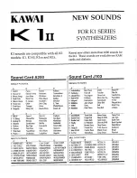
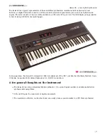
K1
Brand: Kawai Pages: 6
CS-80
Brand: Yamaha Pages: 13

ANTIPHON
Brand: Dreadbox Pages: 21

K3
Brand: Kawai Pages: 35
K3
Brand: Kawai Pages: 19

Polaris
Brand: Fender Pages: 68
120X
Brand: dbx Pages: 12

CS-10
Brand: Yamaha Pages: 19

DX100
Brand: Yamaha Pages: 36
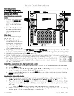
Bitbox
Brand: 1010 Music Pages: 2

Spherical Wavetable Navigator
Brand: 4ms Company Pages: 4

P-300
Brand: Yamaha Pages: 61
WAVE
Brand: P.P.G. Pages: 4

Virus TI
Brand: Access Pages: 186
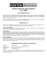
9308
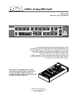
Brand: Paia Pages: 6

RM
Brand: Daedalus Pages: 40
proteus 2000
Brand: E-Mu Pages: 10

CAT
Brand: Octave Pages: 38


