background image

Maintenance and Service Guide

HP EliteDesk 800 G3 TWR Business PC

HP EliteDesk 880 G3 TWR Business PC

Summary of Contents for EliteDesk 800 G3

Page 1: ...Maintenance and Service Guide HP EliteDesk 800 G3 TWR Business PC HP EliteDesk 880 G3 TWR Business PC ...

Page 2: ... describes features that are common to most models Some features may not be available on your computer In accordance with Microsoft s support policy HP does not support the Windows 8 or Windows 7 operating system on products configured with Intel and AMD 7th generation and forward processors or provide any Windows 8 or Windows 7 drivers on http www support hp com Not all features are available in ...

Page 3: ... another hard surface such as an adjoining optional printer or a soft surface such as pillows or rugs or clothing to block airflow Also do not allow the AC adapter to contact the skin or a soft surface such as pillows or rugs or clothing during operation The device and the AC adapter comply with the user accessible surface temperature limits defined by the International Standard for Safety of Info...

Page 4: ...iv Safety warning notice ...

Page 5: ...Electrostatic discharge information 11 Generating static 11 Preventing electrostatic damage to equipment 12 Personal grounding methods and equipment 12 Grounding the work area 12 Recommended materials and equipment 13 Operating guidelines 13 Routine care 14 General cleaning safety precautions 14 Cleaning the Computer Case 14 Cleaning the keyboard 14 Cleaning the monitor 15 Cleaning the mouse 15 Se...

Page 6: ...ions 36 System board connections 37 Installing and removing drives 38 Removing a 5 25 inch drive 38 Installing a 5 25 inch drive 39 Removing a 9 5 mm slim optical drive 41 Installing a 9 5 mm slim optical drive 42 Installing a 9 5 mm slim optical drive 43 Removing a 3 5 inch hard drive 45 Installing a 3 5 inch hard drive 46 Removing a 2 5 inch hard drive 50 Installing a 2 5 inch hard drive 51 Remo...

Page 7: ...g media card reader problems 96 Solving display problems 97 Solving audio problems 101 Solving printer problems 103 Solving keyboard and mouse problems 104 Solving Hardware Installation Problems 106 Solving Network Problems 107 Solving memory problems 110 Solving CD ROM and DVD problems 111 Solving USB flash drive problems 113 Solving front panel component problems 115 Solving Internet access prob...

Page 8: ...er boot order 134 Removing the HP Recovery partition select products only 135 Backing up restoring and recovering in Windows 7 135 Creating recovery media and backups 135 Guidelines 136 Creating recovery media with HP Recovery Disc Creator 136 Creating recovery media 136 Backing up your information 136 Performing a system recovery 137 Using the Windows recovery tools 137 Using f11 recovery tools s...

Page 9: ...Appendix D Specifications 151 TWR Specifications 151 Index 153 ix ...

Page 10: ...x ...

Page 11: ...ng on the model For support assistance and to learn more about the hardware and software installed on your computer model run the HP Support Assistant utility NOTE This computer model can be used in a tower orientation or a desktop orientation Standard configuration features 1 ...

Page 12: ...h HP Sleep and Charge 3 SD card reader optional 9 USB 2 0 port 4 Power button 10 USB 3 x ports 2 5 Hard drive activity light 11 USB Type C charging port 6 Audio out headphone Audio in microphone combo jack NOTE The light on the power button is normally white when the power is on If it is flashing red there is a problem with the computer and it is displaying a diagnostic code Refer to the Maintenan...

Page 13: ... device is plugged into either audio jack a dialog box will appear on the monitor screen asking if you want to use the jack for a microphone or a headphone You can also reconfigure the jacks at any time by double clicking the Audio Manager icon in the Windows taskbar When a graphics card is installed in one of the system board slots the video connectors on the graphics card and or the integrated g...

Page 14: ...ach computer has a unique serial number and a product ID number that are located on the exterior of the computer Keep these numbers available for use when contacting customer service for assistance 4 Chapter 1 Product features ...

Page 15: ...for your computer go to http partsurfer hp com select your country or region and then follow the on screen instructions Item Description 1 Front bezel HP EliteDesk 800 G3 models HP EliteDesk 880 G3 models 2 Access panel 3 System board includes replacement thermal material 4 Fan sink includes replacement thermal material 95 W 65 W 5 Power supply 500W 90 efficient TWR chassis spare parts 5 ...

Page 16: ...cessor Intel Core i5 7600 processor Intel Core i5 7500 processor Intel Core i3 7320 processor Intel Core i3 7300 processor Intel Core i3 7100 processor Intel Core i7 6700 processor Intel Core i5 6600 processor Intel Core i5 6500 processor Intel Core i3 6100 processor Intel Pentium G4620 processor Intel Pentium G4600 processor Intel Pentium G4560 processor Intel Celeron G3950 processor Intel Celero...

Page 17: ...sensor 4 Hood lock 5 Speaker Secure Digital SD card reader Optical drive latch Bezel dust filter Bezel blank main Bezel blank slim optical drive Rubber feet Hard drive grommet Mouse PS2 optical USB laser USB optical USB antimicrobial USB washable TWR chassis spare parts 7 ...

Page 18: ...16 G5 Nvidia GTX 1080 8 GB FH PCIe x16 Graphics card holder bracket WLAN modules Intel 8265 802 11AC 2x2 Wi Fi Bluetooth M 2 Combo Card non VPro Intel 7265 802 11AC 2x2 Wi Fi Bluetooth M 2 Combo Card non VPro Intel 3168 802 11AC 2x2 Wi Fi Bluetooth M 2 Combo Card non VPro Option boards HDMI option board DisplayPort option board USB 3 1 Type C option board VGA option board Serial port Serial PS2 po...

Page 19: ...traight end 1 angled end SATA data cable 14 inch 1 straight end 1 angled end SATA data cable RF solution 14 inch 1 straight end 1 angled end SATA data cable 15 inch 1 straight end 1 angled end SATA data cable RF solution 15 inch 1 straight end 1 angled end Serial port cable Serial PS2 port cable DisplayPort cable 1 8 m DVI to DVI cable Internal antennas Antenna cover Adapters DisplayPort to HDMI 1...

Page 20: ... hybrid SSD 3 5 inch 500 GB 7200 rpm 3 5 inch 500 GB 7200 rpm 7 mm 500 GB 7200 rpm OPAL2 self encrypting drive SED 500 GB 5400 rpm FIPS 500 GB 5400 rpm hybrid SSD Solid state drives 2280 2 5 inch 512 GB FIPS 140 2 256 GB FIPS 140 2 256 GB 128 GB Solid state drives 2280 NVMe M 2 1 TB TLC 512 GB MLC 512 GB TLC 256 GB MLC 256 GB TLC 256 GB PCIe Optical drives 9 5 mm DVD RW drive DVD ROM drive 10 Chap...

Page 21: ...e may function normally for a while but it has been degraded in the internal layers reducing its life expectancy Networks built into many integrated circuits provide some protection but in many cases the discharge contains enough power to alter device parameters or melt silicon junctions Generating static The following table shows that Different activities generate different amounts of static elec...

Page 22: ...t snugly into the banana plug connector on the grounding mat or workstation Heel straps Toe straps Boot straps can be used at standing workstations and are compatible with most types of shoes or boots On conductive floors or dissipative floor mats use them on both feet with a maximum of one megohm 10 resistance between the operator and ground Static Shielding Protection Levels Method Voltage Antis...

Page 23: ...d cold Operate the computer on a sturdy level surface Leave a 10 2 cm 4 inch clearance on all vented sides of the computer and above the monitor to permit the required airflow Never restrict the airflow into the computer by blocking any vents or air intakes Do not place the keyboard with the keyboard feet down directly against the front of the desktop unit as this also restricts airflow Occasional...

Page 24: ...uted with water Rinse well by wiping it with a cloth or swab dampened with clear water For stubborn stains use isopropyl rubbing alcohol No rinsing is needed as the alcohol will evaporate quickly and not leave a residue After cleaning always wipe the unit with a clean lint free cloth Occasionally clean the air vents on the computer Lint and other foreign matter can block the vents and limit the ai...

Page 25: ...ouse ensure that the power to the computer is turned off Clean the mouse ball by first removing the retaining plate and the ball from the housing Pull out any debris from the ball socket and wipe the ball with a clean dry cloth before reassembly To clean the mouse body follow the procedures in Cleaning the Computer Case on page 14 Service considerations Listed below are some of the considerations ...

Page 26: ...applies to failed drives as well as replacement spares If a drive must be mailed place the drive in a bubble pack mailer or other suitable protective packaging and label the package Fragile Handle With Care Do not remove hard drives from the shipping package for storage Keep hard drives in their protective packaging until they are actually mounted in the computer Avoid dropping drives from any hei...

Page 27: ...ble as it is fully backwards compatible with the SATA 1 5 Gb s drives Current HP desktop products ship with SATA 6 0 Gb s hard drives SATA data cables are susceptible to damage if overflexed Never crease a SATA data cable and never bend it tighter than a 30 mm 1 18 in radius The SATA data cable is a thin 7 pin cable designed to transmit data for only a single drive SMART ATA drives The Self Monito...

Page 28: ...arts are moved When folding a flat ribbon cable never fold to a sharp crease Sharp creases may damage the wires Some flat ribbon cables come prefolded Never change the folds on these cables Do not bend any cable sharply A sharp bend can break the internal wires Never bend a SATA data cable tighter than a 30 mm 1 18 in radius Never crease a SATA data cable Do not rely on components like the drive c...

Page 29: ...er 5 Turn off the computer and any peripheral devices that are connected to it CAUTION Turn off the computer before disconnecting any cables Regardless of the power on state voltage is always present on the system board as long as the system is plugged into an active AC outlet In some systems the cooling fan is on even when the computer is in the Standby or Suspend modes The power cord should alwa...

Page 30: ...reparation for disassembly on page 19 2 Slide the access panel release lever to the left 1 so that it locks into place Then slide the access panel back 2 and lift it off the computer 3 To replace the access panel reverse the disassembly procedures 20 Chapter 4 Removal and replacement procedures Microtower MT chassis ...

Page 31: ...aration for disassembly on page 19 2 Remove the access panel Access panel on page 20 3 Lift up the three tabs on the top of the bezel 1 and then rotate the bezel off the chassis 2 To replace the front bezel reverse the disassembly procedures Front bezel 21 ...

Page 32: ...disassembly on page 19 2 Remove the access panel Access panel on page 20 3 Remove the silver 6 32 security screw located inside the front bezel 4 Replace the front bezel 5 Install the security screw through the inside front of the chassis into the front bezel to secure the bezel in place 6 Replace the computer access panel 22 Chapter 4 Removal and replacement procedures Microtower MT chassis ...

Page 33: ...nel Access panel on page 20 3 Remove the front bezel Front bezel on page 21 4 To remove a 5 25 inch optical drive bezel blank press inward on the two tabs on the right side of the blank 1 and then rotate the blank off the front bezel 2 To remove a slim optical drive bezel blank press inward on the tab on the right side of the blank 1 and then rotate the blank away from the front bezel 2 and slide ...

Page 34: ... from HP To remove clean and replace the dust filter 1 Prepare the computer for disassembly Preparation for disassembly on page 19 2 To remove the dust filter use your fingers to separate the filter from the front bezel at the tab locations shown below 3 Use a soft brush or cloth to clean dust from the filter If heavily soiled rinse the filter clean with water To replace the filter reverse the rem...

Page 35: ...A The system will automatically operate in single channel mode dual channel mode or flex mode depending on how the DIMMs are installed NOTE Single channel and unbalanced dual channel memory configurations will result in inferior graphics performance The system will operate in single channel mode if the DIMM sockets are populated in one channel only The system will operate in a higher performing du...

Page 36: ...ble metals in contact with each other Static electricity can damage the electronic components of the computer or optional cards Before beginning these procedures ensure that you are discharged of static electricity by briefly touching a grounded metal object When handling a memory module be careful not to touch any of the contacts Doing so may damage the module 1 Prepare the computer for disassemb...

Page 37: ...tches are in the closed position 3 6 Replace the computer access panel 7 Reconnect the power cord and turn on the computer 8 Lock any security devices that were disengaged when the access panel was removed The computer should automatically recognize the additional memory the next time you turn on the computer Memory 27 ...

Page 38: ...ide the drive cage back and lift it out of the chassis 3 4 Use a soft brush or cloth to clean dust from the filter If heavily soiled rinse the filter clean with water To replace the drive cage reverse the removal procedures When replacing the drive cage align the rivets on the front of the cage with the slots on the chassis press the front of the cage down into the slots and then slide the cage fo...

Page 39: ...Drive cage 29 ...
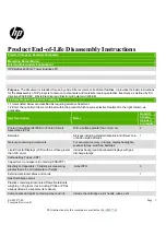
Page 40: ... vacant expansion socket on the system board and the corresponding expansion slot on the back of the computer chassis 4 Release the slot cover retention latch that secures the slot covers by lifting the tab on the latch and rotating the latch to the open position 5 Before installing an expansion card remove the expansion slot cover or the existing expansion card NOTE Before removing an installed e...

Page 41: ...ot covers must be removed with a screwdriver Insert a flat bladed screwdriver into the slots on the rear of the slot cover 1 and rock the slot cover back and forth 2 to break it free from the chassis Expansion cards 31 ...

Page 42: ... until the connectors pull free from the socket Lift the card straight up 2 and then away from the inside of the chassis 3 to remove it Be sure not to scrape the card against other components NOTE If the card is full length you may need to remove the drive cage to remove the card 6 Store the removed card in anti static packaging 7 If you are not installing a new expansion card install an expansion...

Page 43: ... the expansion card socket 9 To install a full length expansion card you must remove the hard drive cage to allow room for installing the card Drive cage on page 28 a To install a full length expansion card hold the card just above the expansion socket on the system board then move the card toward the rear of the chassis 1 so that the bottom of the bracket on the card slides into the small slot on...

Page 44: ...onnect internal cables to the system board if needed 12 Replace the computer access panel 13 Reconnect the power cord and turn on the computer 14 Lock any security devices that were disengaged when the computer access panel was removed 15 Reconfigure the computer if necessary 34 Chapter 4 Removal and replacement procedures Microtower MT chassis ...

Page 45: ...ews installed on top of the drive bay IMPORTANT To prevent loss of work and damage to the computer or drive If you are inserting or removing a drive shut down the operating system properly turn off the computer and unplug the power cord Do not remove a drive while the computer is on or in standby mode Before handling a drive be sure that you are discharged of static electricity While handling a dr...

Page 46: ... 5 mm slim optical drive bay 5 3 5 inch primary hard drive bay NOTE The drive configuration on your computer may be different than the drive configuration shown above To verify the type and size of the storage devices installed in the computer run Computer Setup 36 Chapter 4 Removal and replacement procedures Microtower MT chassis ...

Page 47: ... SATA3 Light blue Slim optical drive 6 DIMM4 Channel A DIMM4 White Memory module 7 DIMM3 Channel A DIMM3 Black Memory module 8 DIMM2 Channel B DIMM2 White Memory module 9 DIMM1 Channel B DIMM1 Black Memory module 10 Battery BAT Black Battery 11 SATA 3 0 SATA1 Light blue Any SATA device other than the primary hard drive 12 SATA 3 0 SATA0 Dark blue Primary hard drive 13 M 2 WLAN WLAN Black M 2 WLAN ...

Page 48: ...cess panel Access panel on page 20 3 Remove the front bezel Front bezel on page 21 4 Disconnect the power cable 1 and data cable 2 from the rear of the drive IMPORTANT When removing the cables pull the tab or connector instead of the cable itself to avoid damaging the cable 5 Push the green drivelock mechanism towards the optical drive 1 and then slide the drive from the drive bay 2 38 Chapter 4 R...

Page 49: ...lank remove the bezel blank See Removing bezel blanks on page 23 for more information 4 If you are installing an optical drive install four M3 metric mounting screws not provided in the lower holes on each side of the drive NOTE When replacing an optical drive transfer the four M3 metric mounting screws from the old drive to the new one IMPORTANT Use only 5 mm long screws as mounting screws Longer...

Page 50: ... flat bladed screwdriver into the slots on the front of the shield 1 and rock the shield back and forth 2 to break it free from the chassis 6 Slide the drive into the drive bay making sure to align the mounting screws with the mounting slots until the drive snaps into place 40 Chapter 4 Removal and replacement procedures Microtower MT chassis ...

Page 51: ... Reassemble the computer Removing a 9 5 mm slim optical drive CAUTION All removable media should be taken out of a drive before removing the drive from the computer 1 Prepare the computer for disassembly Preparation for disassembly on page 19 2 Remove the access panel Access panel on page 20 3 Disconnect the power cable 1 and data cable 2 from the rear of the drive IMPORTANT When removing the cabl...

Page 52: ...ess panel Access panel on page 20 3 Remove the front bezel Front bezel on page 21 If you are installing a drive in a bay covered by a bezel blank remove the bezel blank See Removing bezel blanks on page 23 for more information 4 Disconnect the power cable 1 and data cable 2 from the rear of the drive IMPORTANT When removing the cables pull the tab or connector instead of the cable itself to avoid ...

Page 53: ...sembly Preparation for disassembly on page 19 2 Remove the access panel Access panel on page 20 3 If you are installing a slim optical drive in a bay covered by a bezel blank remove the front bezel and then remove the bezel blank See Removing bezel blanks on page 23 for more information 4 Align the small pin on the release latch with the small hole on the side of the drive and press the latch firm...

Page 54: ...le 1 and data cable 2 to the rear of the optical drive 7 Connect the opposite end of the data cable to one of the light blue SATA connectors on the system board NOTE Refer to System board connections on page 37 for an illustration of the system board drive connectors 8 Reassemble the computer 44 Chapter 4 Removal and replacement procedures Microtower MT chassis ...

Page 55: ... disassembly Preparation for disassembly on page 19 2 Remove the access panel Access panel on page 20 3 Remove the drive cage Drive cage on page 28 4 Remove the drive from the drive cage by pulling the release tab away from the drive 1 and sliding the drive out of the bay 2 5 Remove the four mounting screws two on each side from the old drive You will need these screws if you install a new drive D...

Page 56: ... the hard drive bays Refer to Installing and removing drives on page 38 for an illustration of the extra 6 32 mounting screws location If you are replacing a drive transfer the mounting screws from the old drive to the new drive Install four silver and blue 6 32 mounting screws two on each side of the drive You can also install a 2 5 inch hard drive into a 3 5 inch drive bay using an adapter brack...

Page 57: ... Secure the drive to the bay adapter bracket by installing four black M3 adapter bracket screws through the underside of the bracket and into the drive Drives 47 ...

Page 58: ...he drive cage if it was not already removed Drive cage on page 28 5 Slide the drive into the drive bay making sure to align the mounting screws with the mounting slots until the drive snaps into place 6 Replace the drive cage Drive cage on page 28 48 Chapter 4 Removal and replacement procedures Microtower MT chassis ...

Page 59: ...e data cable to the appropriate system board connector NOTE You must connect the primary hard drive data cable to the dark blue connector labeled SATA0 to avoid any hard drive performance problems If you are adding a second hard drive connect the data cable to one of the light blue SATA connectors 9 Reassemble the computer Drives 49 ...

Page 60: ...0 3 Disconnect the power cable 1 and data cable 2 from the rear of the hard drive 4 Pull the release lever at the rear of the drive outward 1 and pull the rear of the drive outward 2 Then slide the front of the drive forward until it stops and pull the drive up and out of the drive bay 3 50 Chapter 4 Removal and replacement procedures Microtower MT chassis ...

Page 61: ... drive NOTE M3 metric mounting screws can be purchased from HP When replacing a drive transfer the four mounting screws from the old drive to the new drive 4 Align the front mounting screws on the drive with the J slots on the sides of the drive bay Press the front of the drive into the drive bay and then slide the drive forward 1 Then press the rear of the drive into the drive bay 2 so that the d...

Page 62: ...n the system board 6 Reassemble the computer Removing and installing an M 2 SSD storage card NOTE The computer supports 2230 and 2280 M 2 SSD cards 1 Prepare the computer for disassembly Preparation for disassembly on page 19 2 Remove the access panel Access panel on page 20 3 Remove the drive cage Drive cage on page 28 4 To remove an M 2 SSD card remove the screw that secures the card 1 lift the ...

Page 63: ...ard into the system board connector while holding the card at approximately a 30 angle 1 Press the other end of the card down 2 and then secure the card with the screw 3 6 Replace the drive cage Drive cage on page 28 and reassemble the computer Drives 53 ...

Page 64: ...AN antenna cable labeled 1 connects to the WLAN module Main terminal labeled 1 The WLAN antenna cable labeled 2 connects to the WLAN module Aux terminal labeled 2 4 Remove the Phillips PM2 0 3 0 screw 2 that secures the WLAN module to the computer The edge of the module opposite the slot rises away from the computer 5 Remove the WLAN module 3 by pulling the module away from the slot at an angle NO...

Page 65: ...sassembly on page 19 2 Remove the computer access panel Access panel on page 20 3 Remove the front bezel Front bezel on page 21 4 Remove the drive cage Drive cage on page 28 5 From the inside of the computer disconnect the cables from the following system board connectors FRONT USB blue connector PB LED black connector FRONT USB 3 1 blue connector FRONT USB 3 1 TYPE C black connector FRONT USB yel...

Page 66: ...vary 7 Rotate the right side of the assembly away from the computer and then pull the assembly out of the front of the chassis while threading the cables through the hole in the front of the chassis To reinstall the assembly reverse the removal procedure 56 Chapter 4 Removal and replacement procedures Microtower MT chassis ...

Page 67: ... if you cannot warm the fan sink prior to removal Inadvertently removing the processor can damage the pins 1 Prepare the computer for disassembly Preparation for disassembly on page 19 2 Remove the access panel Access panel on page 20 3 Loosen the four silver captive Torx T15 screws 1 that secure the fan sink to the system board CAUTION Remove fan sink retaining screws in diagonally opposite pairs...

Page 68: ...ease has been applied to the top of the processor CAUTION Fan sink retaining screws should be tightened in diagonally opposite pairs as in an X to evenly seat the fan sink on the processor This is especially important as the pins on the socket are very fragile and any damage to them may require replacing the system board 58 Chapter 4 Removal and replacement procedures Microtower MT chassis ...

Page 69: ...N Do NOT handle the pins in the processor socket These pins are very fragile and handling them could cause irreparable damage Once pins are damaged it may be necessary to replace the system board The heat sink must be installed within 24 hours of installing the processor to prevent damage to the processor s solder connections Reverse the removal procedure to install a new processor NOTE After inst...

Page 70: ...panel on page 20 3 Remove the drive cage Drive cage on page 28 4 Disconnect the speaker cable from the system board connector labeled SPKR 1 5 Remove the Torx T15 screw 2 that secures the speaker to the chassis 6 Slide the speaker to the right and the remove the speaker from the chassis 3 To replace the speaker reverse the removal procedures 60 Chapter 4 Removal and replacement procedures Microtow...

Page 71: ...move the access panel Access panel on page 20 3 Remove the three silver Phillips screws that secure the fan to the rear of chassis 4 Disconnect the fan control cable 1 from the system board connector labeled CHFAN2 5 Lift the fan out of the chassis 2 To install the fan assembly reverse the removal procedure Be sure to orient the air flow out of the chassis Rear fan 61 ...

Page 72: ...ccess panel on page 20 3 From the rear of the chassis remove the two security screws that secure the hood lock 4 From the inside of the chassis disconnect the cable from the system board connector labeled HLCK 1 5 Remove the hood lock from the inside of the computer 2 To install the hood lock reverse the removal procedure 62 Chapter 4 Removal and replacement procedures Microtower MT chassis ...

Page 73: ... 19 2 Remove the access panel Access panel on page 20 3 Disconnect the cable from the system board connector labeled HSENSE 1 4 Slide the hood sensor out of the slot on the rear of the chassis 2 A tool such as a screwdriver may be required to pry the hood sensor from the slot To install the hood sensor reverse the removal procedure Hood sensor 63 ...

Page 74: ...isassembly on page 19 2 Remove the access panel Access panel on page 20 3 Remove the drive cage Drive cage on page 28 4 Remove the three Torx T15 screws that connect the power supply to the rear of the chassis 5 From the inside of the chassis remove the power supply cables from the clips built into the bottom of the chassis 6 Disconnect the power supply cables from the following system board conne...

Page 75: ...7 Disconnect the power supply cables from the following system board connectors PWRCPU PWR Power supply 65 ...

Page 76: ...ower supply 1 slide the power supply toward the front of the computer 2 and then lift the power supply out of the chassis To install the power supply reverse the removal procedure 66 Chapter 4 Removal and replacement procedures Microtower MT chassis ...

Page 77: ... a serial port expansion board To remove the option board 1 Prepare the computer for disassembly Preparation for disassembly on page 19 2 Remove the access panel Access panel on page 20 3 Remove the two Phillips screws 1 that secure the board to the system board 4 Lift to disengage the board from the system board connector and then remove the option board from the computer 2 To install the option ...

Page 78: ...disassembly Preparation for disassembly on page 19 2 Remove the access panel Access panel on page 20 3 Remove the drive cage Drive cage on page 28 4 From the front of the computer remove the Torx T15 screw that secures the antenna to the computer NOTE Chassis color may vary 68 Chapter 4 Removal and replacement procedures Microtower MT chassis ...

Page 79: ...5 From the inside rear of the computer press the tab that secures the antenna cover to the computer 6 From the outside rear of the computer rotate the cover up and off the computer Antennas 69 ...

Page 80: ...e the Torx T15 screw that secures the antenna to the computer 8 From inside of the computer disconnect both antennas from the WLAN module 1 70 Chapter 4 Removal and replacement procedures Microtower MT chassis ...

Page 81: ...ape that secures them to the computer 2 and then thread both antennas through the holes front and rear from the inside to outside of the computer 3 Reverse the removal procedure to install the WLAN antennas and transceivers Antennas 71 ...

Page 82: ... page 52 WLAN module WLAN module on page 54 Heat sink Fan sink on page 57 Processor Processor on page 59 4 Disconnect all cables connected to the system board noting their location for reinstallation 5 Remove the eight Torx T15 screws that secure the system board to the chassis 6 Lift the board up and out of the computer When reinstalling the system board first insert the I O panel back into the s...

Page 83: ...te Speaker X1PCIEXP1 Black Expansion card FRONT USB3 0 Blue Front I O power switch X16PCIEXP White Expansion card SD RDR Black Card reader COMB Black Optional second serial port EXT Black Extension board HLCK Black Hood lock SATA3 Light blue Any SATA Device other than the primary hard drive PWRCPU White 4 pin processor power SATA0 Dark blue Primary hard drive System board 73 ...

Page 84: ... O DIMM4 White Memory module SATA2 Light blue Any SATA Device other than the primary hard drive DIMM3 Black Memory module PSWD Green Clear system passwords DIMM2 White Memory module CMOS Yellow Reset CMOS DIMM1 Black Memory module BAT Black RTC battery PB LED Black Front I O power switch HSENSE White Hood sensor PWRCMD White Power supply THUNDERBOLT Black Thunderbolt connector SATAPWR0 Black Drive...

Page 85: ... different types of boot sources Configure features such as Secure Boot power management virtualization support and language and keyboard type used in Setup and POST Replicate the system setup by saving system configuration information on a USB device and restoring it on one or more computers Enable or disable DriveLock security or securely erase a hard drive when supported by drive Using Computer...

Page 86: ...anced and Main menus to those previously saved by Save Custom Defaults select Apply Custom Defaults and Exit If no custom defaults have been saved then factory defaults are used NOTE Settings in the Security menu are not modified by Apply Defaults Those values are reset by Restore Security Settings to Factory Defaults at the bottom of the Security menu NOTE Not all settings shown in the following ...

Page 87: ...e Firmware System BIOS version ME Firmware version Intel only Video BIOS version Reference code version Super I O Firmware version USB Type C controller s firmware version Service Born on date Serial number SKU number UUID Universally Unique Identifier Asset tracking number Feature byte Build ID Product family System board ID System board CT number Communication Integrated MAC Address System Diagn...

Page 88: ...r the minimum BIOS version that can be rolled back to Unrestricted rollback to older BIOS Restricted rollback to older BIOS Allow BIOS updates using a network BIOS Update Preferences Allows the administrator to select the source of network updates www hp com or another network server and allows configuration of a periodic check for updates including policies for Check for updates and prompt the us...

Page 89: ... password which controls access to the following features Setup Menu F10 3rd Party Option ROM Management F3 Update system ROM WMI commands that change system settings BIOS Configuration Utility BCU Alternative power on password NOTE Creating a BIOS user disables the Fast Boot option NOTE If the password is set it is required to change Computer Setup options update the BIOS and make changes to cert...

Page 90: ...o allows you to recover the last known good MBR should changes to the MBR be detected when the system is restarted NOTE Most operating systems control access to the MBR of the current bootable disk the BIOS cannot prevent changes that may occur while the operating system is running Restores the backup Master Boot Record to the current bootable disk Default is disabled Only appears if all of the fo...

Page 91: ... devices clears BIOS passwords not including DriveLock and restores settings in the Security menu to factory defaults Computer Setup Advanced NOTE Support for specific Computer Setup options may vary depending on the hardware configuration Table 5 3 Computer Setup Advanced for advanced users Option Heading Display Language Lets you select the language of the menus in F10 Setup and the keyboard lay...

Page 92: ...OS booting preventing firmware attacks UEFI and Windows Secure Boot only allow code signed by pre approved digital certificates to run during the firmware and OS boot process Legacy Support Enable and Secure Boot Disable Legacy Support Disable and Secure Boot Enable Legacy Support Disable and Secure Boot Disable Default is Legacy Support Disable and Secure Boot Disable Secure Boot Key Management L...

Page 93: ...sec Built In Device Options Embedded LAN Controller Select to show the device in the operating system Default is enabled Wake On LAN Lets you either disable the Wake On LAN feature or configure where the computer boots including the network or hard drive Default is Boot to Network Dust Filter Select to enable the Dust Filter replacement reminder which can be set for 15 30 60 90 120 or 180 days The...

Page 94: ... USB Type C Controller Firmware Update Default is enabled Option ROM Launch Policy These policies control whether Legacy Option ROMs or UEFI drivers are loaded Default is All legacy for Windows 7 and other non Windows configurations Default is All UEFI for Windows 10 or later Configure Option ROM Launch Policy All legacy All UEFI All UEFI except video Power Management Options Runtime Power Managem...

Page 95: ...e Default is disabled USB Redirection Support enable disable Default is enabled USB redirection allows USB devices plugged into a client computer to be transparently redirected to the guest operating system Unconfigure AMT on next boot Do Not Apply Apply Default is Do Not Apply SOL Terminal Emulation Mode ANSI VT100 Default is ANSI SOL terminal emulation mode is only activated during remote AMT re...

Page 96: ... to Removable Media option creates a file named HPSETUP TXT on an inserted USB flash media device This file can be edited to change the settings on Restore An asterisk marks the selected option for a setting NOTE It is recommended that you save any modified computer configuration settings to a USB flash media device and save the device for possible future use To restore the configuration insert th...

Page 97: ...d The flashing lights are error codes that will help you diagnose the problem Refer to POST error messages and diagnostic front panel LEDs and audible codes on page 118 for more information If the screen is blank plug the monitor into a different video port on the computer if one is available Or replace the monitor with a monitor that you know is functioning properly If you are working on a networ...

Page 98: ... green monitor light is on Check the Power LED on the front of the computer to see if it is flashing red The flashing lights are error codes that will help you diagnose the problem Refer to POST error messages and diagnostic front panel LEDs and audible codes on page 118 for more information Turn up the brightness and contrast controls of the monitor if the monitor is dim Press and hold any key If...

Page 99: ... is always applied to the system board To reduce the risk of personal injury from electrical shock and or hot surfaces be sure to disconnect the power cord from the wall outlet and allow the internal system components to cool before touching Cannot access the Computer Setup F10 Utility when booting the computer Cause Solution The Computer Setup F10 Utility is set to fast boot causing the F10 acces...

Page 100: ...sure the external speakers are properly connected and powered on and that the speakers volume control is set correctly 3 Use the system volume control available in the operating system to make sure the speakers are not muted or to increase the volume Cannot remove computer cover or access panel Cause Solution Smart Cover Lock featured on some computers is locked Unlock the Smart Cover Lock using C...

Page 101: ...Utility click Open Task Manager c Select applications that you do not want to launch automatically and the click Disable Some software applications especially games are stressful on the graphics subsystem 1 Lower the display resolution for the current application or consult the documentation that came with the application for suggestions on how to improve performance by adjusting parameters in the...

Page 102: ...e system board turns on 3 Replace the system board OR Press and hold the power button for less than 4 seconds If the hard drive LED does not turn on white then 1 Check that the unit is plugged into a working AC outlet 2 Open the access panel and check that the power button cable is properly connected to the system board 3 Check that the power supply cables are properly connected to the system boar...

Page 103: ...or other system fan spins If the fan does not spin make sure the fan cable is plugged onto the system board header 3 If fan a plugged in and not spinning replace it Power LED flashes Red four times once every second followed by a two second pause and the computer beeps four times Beeps stop after fifth iteration but LEDs continue flashing Computer powered off automatically and the Power LED flashe...

Page 104: ... from the list of applications In the left column expand This PC right click on a drive select Properties and then select the Tools tab Under Error checking click Check Drive not found identified Cause Solution Cable could be loose Check cable connections The system may not have automatically recognized a newly installed device See reconfiguration directions in the Solving Hardware Installation Pr...

Page 105: ...ed Boot Options and ensure the bootable hard drive is listed immediately under the Hard Drive entry Computer will not boot from hard drive Cause Solution The device is attached to a SATA port that has been hidden in Computer Setup 1 Check SATA cable connections 2 Run the Computer Setup utility and ensure Device Available is selected for the device s SATA port in Advanced Port Options Boot order is...

Page 106: ...ous section for a list of compatible cards Media card is locked Locking the media card is a safety feature that prevents writing to and deleting from an SD Memory Stick PRO card If using an SD card make sure that the lock tab located on the right of the SD card is not in the locked position If using a Memory Stick PRO card make sure that the lock tab located on the bottom of the Memory Stick PRO c...

Page 107: ...that the monitor light is on Bad monitor Try a different monitor The cable connections are not correct Check the cable connection from the monitor to the computer and to the electrical outlet You may have a screen blanking utility installed or energy saver features are enabled Press any key or click the mouse button and type your password if set System ROM is corrupted system is running in Boot Bl...

Page 108: ...e Solution Pre video memory error 1 Reseat DIMMs Power on the system 2 Replace DIMMs one at a time to isolate the faulty module 3 Replace third party memory with HP memory 4 Replace the system board Blank screen and the power LED flashes Red six times once every second followed by a two second pause and the computer beeps six times Beeps stop after fifth iteration but LEDs continue flashing Cause ...

Page 109: ...displaying requested resolution Change requested resolution Graphics card is bad Replace the graphics card The picture is broken up rolls jitters or flashes Cause Solution The monitor connections may be incomplete or the monitor may be incorrectly adjusted 1 Be sure the monitor cable is securely connected to the computer 2 In a two monitor system or if another monitor is in close proximity be sure...

Page 110: ...e mode Safe Mode displays in the corners of your monitor To exit safe mode restart your computer and let Windows start normally To enter Safe Mode in Windows 10 1 Log into the computer using an Administrator account 2 Type msconfig in the taskbar search box and then select msconfig from the list of applications 3 Click the Boot tab select Safe boot and then click OK High pitched noise coming from ...

Page 111: ...and then select Character Map from the list of applications Solving audio problems If the computer has audio features and you encounter audio problems see the common causes and solutions listed in the following table Headset microphone connected to the front is not working or is very quiet Cause Solution The front Headset connector supports CTIA Cellular Telephone Industries Association style head...

Page 112: ... speaker in Computer Setup Select Advanced Built in Device Options The application is set to use a different audio device than speakers Some graphics cards support audio over the DisplayPort connection if applicable so multiple audio devices may be listed in Device Manager Make sure the correct device is being used To access Device Manager in Windows 7 click Start select Control Panel and then sel...

Page 113: ...ed the correct audio device The operating system controls may be set to use a different audio device as the default output device than what is expected Set the operating system to use the correct audio device Solving printer problems If you encounter printer problems see the documentation that came with the printer and to the common causes and solutions listed in the following table Printer will n...

Page 114: ...correctly Symptoms include lagging mouse movement jumpy mouse keyboard or no function of mouse keyboard and external drive Cause Solution If your computer is equipped with USB 3 0 ports connected USB 3 0 devices can interfere with the wireless keyboard USB receiver Connect the wireless keyboard USB receiver to a USB 2 0 port that is separated from ports with USB 3 0 devices If you still experience...

Page 115: ...e menu and then press Enter 3 Use the arrow keys to select Shut Down and then press Enter 4 After the shutdown is complete plug the mouse connector into the back of the computer or the keyboard and restart Program in use has stopped responding to commands Shut down the computer using the keyboard then restart the computer Mouse may need cleaning Remove the roller ball cover on the mouse and clean ...

Page 116: ...s not turned on Turn off the computer turn on the external device then turn on the computer to integrate the device with the computer system When the system advised you of changes to the configuration you did not accept them Reboot the computer and follow the instructions for accepting the changes A plug and play board may not automatically configure when added if the default configuration conflic...

Page 117: ...arty memory with HP memory 4 Replace the system board Solving Network Problems Some common causes and solutions for network problems are listed in the following table These guidelines do not discuss the process of debugging the network cabling Table 6 2 Solving Network Problems Network driver does not detect network controller Cause Solution Network controller is disabled 1 Run Computer Setup and ...

Page 118: ...roperly loaded Reinstall network drivers System cannot autosense the network Disable auto sensing capabilities and force the system into the correct operating mode Diagnostics reports a failure Cause Solution The cable is not securely connected Ensure that the cable is securely attached to the network connector and that the other end of the cable is securely attached to the correct device The cabl...

Page 119: ...install the network drivers using the Recovery Disc Set in Windows 7 If necessary download the softpaq from the web from a different computer The cable is not securely connected Ensure that the cable is securely attached to the network connector and that the other end of the cable is securely attached to the correct device The network controller is defective Contact an authorized service provider ...

Page 120: ... firmware for Out of Band OOB third party data storage and other management functions System will not boot or does not function properly after installing additional memory modules Cause Solution A memory module is not installed in the DIMM1 or XMM1 socket Ensure that a memory module is installed in the DIMM1 or XMM1 socket on the system board This socket must be populated with a memory module Memo...

Page 121: ...s attached to a SATA port that has been hidden in the Computer Setup utility Run the Computer Setup utility and ensure Device Available is selected for the device s SATA port in Advanced Port Options Removable Media Boot is disabled in the Computer Setup utility Run the Computer Setup utility and enable booting to removable media in Advanced Boot Options Network Boot is enabled in Computer Setup R...

Page 122: ...t installed Install decoder software Damaged media Replace media Movie rating locked out by parental lock Use DVD software to remove parental lock Media installed upside down Reinstall media Cannot eject compact disc tray load unit Cause Solution Disc not properly seated in the drive Turn off the computer and insert a thin metal rod into the emergency eject hole and push firmly Slowly pull the tra...

Page 123: ...y media type 1 Try using a slower speed when recording 2 Verify that you are using the correct media for the drive 3 Try a different brand of media Quality varies widely between manufacturers Solving USB flash drive problems If you encounter USB flash drive problems common causes and solutions are listed in the following table USB flash drive is not seen as a drive letter in Windows Cause Solution...

Page 124: ...etup utility Run the Computer Setup utility and enable booting to removable media in Advanced Boot Options Ensure USB is enabled in Storage Boot Order The computer boots to DOS after making a bootable flash drive Cause Solution Flash drive is bootable Install the flash drive only after the operating system boots Flash drive is defective Try a different flash drive 114 Chapter 6 Troubleshooting wit...

Page 125: ...he common causes and solutions listed in the following table Unable to connect to the Internet Cause Solution Internet Service Provider ISP account is not set up properly Verify Internet settings or contact your ISP for assistance Web browser is not set up properly Verify that the Web browser is installed and set up to work with your ISP Cable DSL modem is not plugged in Plug in cable DSL modem Yo...

Page 126: ...ox and then select Control Panel from the list of applications 2 Click Internet Options 3 In the Browsing history section click the Delete button 4 Select the Cookies and website data check box and click the Delete button Cannot automatically launch Internet programs Cause Solution You must log on to your ISP before some programs will start Log on to your ISP and launch the desired program 116 Cha...

Page 127: ...mputer will not continue and the HP logo does not display Cause Solution ROM issue POST error has occurred Observe the beeps and LED lights on the front of the computer See POST error messages and diagnostic front panel LEDs and audible codes on page 118 to determine possible causes See the Worldwide Limited Warranty for terms and conditions Illegal Operation has Occurred error message is displaye...

Page 128: ...hedule reconfigure the computer to the Full Boot Every x Days mode using Computer Setup NOTE For more information on Computer Setup see Computer Setup F10 Utility on page 75 POST numeric codes and text messages This section covers those POST errors that have numeric codes associated with them The section also includes some text messages that may be encountered during POST NOTE The computer will be...

Page 129: ...g POST execution of the Management Engine ME BIOS Extensions option ROM 1 Reboot the computer 2 Unplug the power cord re seat the memory modules and reboot the computer 3 If the memory configuration was recently changed unplug the power cord restore the original memory configuration and reboot the computer 4 If the error persists replace the system board 00C PMM Deallocation Error during MEBx Clea...

Page 130: ...cal SPD information or is incompatible with the chipset 1 Verify proper memory module type 2 Try another memory socket 3 Replace with a supported module 2E4 DIMM Configuration Warning The current memory configuration is not optimized Rearrange the DIMMs so that each channel has the same amount of memory 2E5 ECC Memory Module Detected on Unsupported Platform Recently added memory module s support E...

Page 131: ...ot found Insert boot device or load operating system 3F1 Hard Disk 1 Error Hard disk 1 error 1 Check and or replace cables 2 Clear CMOS See Password security and resetting CMOS on page 125 3 Replace the hard disk drive 3F2 Hard Disk 2 Error Hard disk 2 error 1 Check and or replace cables 2 Clear CMOS See Password security and resetting CMOS on page 125 3 Replace the hard disk drive 400 Serial Port...

Page 132: ...n the system board 43B More Than One USB type C Cards Are Installed More than one USB type C card is installed Remove USB type C card so only one is installed 500 BIOS Recovery A system BIOS recovery has occurred Not applicable 70x Wireless Mode Not Supported The system has detected a wireless module installed in the system that is not supported and has been disabled Replace with a supported modul...

Page 133: ... has proper airflow 90E Power Supply Fan Not detected Power supply fan is not connected or may have malfunctioned 1 Reseat power supply fan 2 Reseat fan cable 3 Replace power supply fan 910 Filter Warning Airflow filter is dirty Replace the airflow filter Interpreting system validation diagnostic front panel LEDs and audible codes During the system validation phase that occurs at system startup th...

Page 134: ...e 2 4 The embedded controller is checking or recovering the boot block Hardware 3 2 The embedded controller has timed out waiting for BIOS to return from memory initialization 3 3 The embedded controller has timed out waiting for BIOS to return from graphics initialization 3 4 The system board displays a power failure crowbar 3 5 The processor is not detected 3 6 The processor does not support an ...

Page 135: ...OS button with power removed will reset the BIOS settings to factory defaults It may be useful to back up the BIOS settings or save them as custom defaults before resetting them in case they are needed later Back up can be performed in Computer Setup or using the BiosConfigUtility tool available from www hp com See Computer Setup F10 Utility on page 75 for information on backing up the BIOS settin...

Page 136: ...rged of static electricity by briefly touching a grounded metal object See the Safety Regulatory Information guide for more information 3 Remove the access panel 4 Locate the header and jumper NOTE The password jumper is green so that it can be easily identified For assistance locating the password jumper and other system board components see the system board components image at System board callo...

Page 137: ... electricity by briefly touching a grounded metal object See the Safety Regulatory Information guide for more information 3 Remove the access panel CAUTION Pushing the CMOS button will reset CMOS values to factory defaults It is important to back up the computer CMOS settings before resetting them in case they are needed later Back up is easily done through Computer Setup See Computer Setup F10 Ut...

Page 138: ...e following order a Connected USB drive NOTE To download the HP PC Hardware Diagnostics UEFI tool to a USB drive see Downloading HP PC Hardware Diagnostics UEFI to a USB device on page 128 b Hard drive c BIOS 3 When the diagnostic tool opens select the type of diagnostic test you want to run and then follow the on screen instructions NOTE If you need to stop a diagnostic test press esc Downloading...

Page 139: ...automatically detect your product 4 Select your computer and then select your operating system 5 In the Diagnostic section follow the on screen instructions to select and download the UEFI version you want Downloading HP PC Hardware Diagnostics UEFI to a USB device 129 ...

Page 140: ...reates a backup of the HP Recovery partition on the computer The backup can be used to reinstall the original operating system in cases where the hard drive is corrupted or has been replaced For information on creating recovery media see Creating HP Recovery media select products only on page 130 For information on the recovery options that are available using the recovery media see Using Windows ...

Page 141: ...tely to create recovery discs If you use an external optical drive it must be connected directly to a USB port on the computer the drive cannot be connected to a USB port on an external device such as a USB hub If you cannot create DVD media yourself you can obtain recovery discs for your computer from HP See the Worldwide Telephone Numbers booklet included with the computer You can also find cont...

Page 142: ...very Manager offers the Remove Recovery Partition option For more information see Removing the HP Recovery partition select products only on page 135 Recovering using HP Recovery Manager HP Recovery Manager software allows you to recover the computer to its original factory state by using the HP Recovery media that you either created or that you obtained from HP or by using the HP Recovery partiti...

Page 143: ...le keyboard connect the keyboard to the keyboard dock before beginning these steps select products only 1 Type recovery in the taskbar search box select Recovery Manager and then select HP Recovery Environment or For computers or tablets with keyboards attached press f11 while the computer boots or press and hold f11 as you press the power button For tablets without keyboards Turn on or restart th...

Page 144: ...ery media 2 Access the system Startup menu For computers or tablets with keyboards attached Turn on or restart the computer or tablet quickly press esc and then press f9 for boot options For tablets without keyboards Turn on or restart the tablet and then quickly hold down the volume up button then select f9 or Turn on or restart the tablet and then quickly hold down the volume down button then se...

Page 145: ...recovery media and backups Recovery after a system failure is only as good as your most recent backup 1 After you successfully set up the computer create HP Recovery media This step creates a Windows 7 operating system DVD and a Driver Recovery DVD The Windows DVD can be used to reinstall the original operating system in cases where the hard drive is corrupted or has been replaced The Driver Recov...

Page 146: ...edia will not be available after you create a Windows DVD To create the Windows DVD 1 Select Start select All Programs select Productivity and Tools and then select HP Recovery Disc Creator 2 Select Windows disk 3 From the drop down menu select the drive for burning the recovery media 4 Click the Create button to start the burning process After the Windows 7 operating system DVD has been created c...

Page 147: ...uter provides the following tools to recover your files Windows recovery tools You can use Windows Backup and Restore to recover information you have previously backed up You can also use Windows Startup Repair to fix problems that might prevent Windows from starting correctly f11 recovery tools select products only You can use the f11 recovery tools to recover your original hard drive image The i...

Page 148: ...press f8 before the Windows operating system loads 4 Select Startup Repair 5 Follow the on screen instructions NOTE For additional information on recovering information using the Windows tools select Start and then select Help and Support Using f11 recovery tools select products only CAUTION Using f11 completely erases hard drive contents and reformats the hard drive All files that you have create...

Page 149: ...t you have created and any software that you have installed on the computer are permanently removed When reformatting is complete the recovery process helps you restore the operating system as well as drivers software and utilities To initiate recovery using a Windows 7 operating system DVD NOTE This process takes several minutes 1 If possible back up all personal files 2 Restart the computer and ...

Page 150: ...y can be extended by plugging the computer into a live AC wall socket The lithium battery is only used when the computer is NOT connected to AC power HP encourages customers to recycle used electronic hardware HP original print cartridges and rechargeable batteries For more information about recycling programs go to http www hp com recycle 1 Remove disengage any security devices that prohibit open...

Page 151: ...metal clamp that extends above one edge of the battery When the battery pops up lift it out 1 b To insert the new battery slide one edge of the replacement battery under the lip of the holder with the positive side up Push the other edge down until the clamp snaps over the other edge of the battery 2 Type 3 a Pull back on the clip 1 that is holding the battery in place and remove the battery 2 141...

Page 152: ...mplete this procedure 8 Replace the computer access panel 9 Plug in the computer and turn on power to the computer 10 Reset the date and time your passwords and any special system setups using Computer Setup 11 Lock any security devices that were disengaged when the computer access panel was removed 142 Appendix A Battery replacement ...

Page 153: ...ited agency responsible for evaluation in the country where the power cord set will be installed 2 The power cord set must have a minimum current capacity of 10A 7A Japan only and a nominal voltage rating of 125 or 250 volts AC as required by each country s power system 3 The diameter of the wire must be a minimum of 0 75 mm2 or 18AWG and the length of the cord must be between 1 8 m 6 feet and 3 6...

Page 154: ... fittings appliance coupler and wall plug must bear the certification mark of the agency responsible for evaluation in the country where it will be used 2 The flexible cord must be Type SVT or equivalent No 18 AWG 3 conductor The wall plug must be a two pole grounding type with a NEMA 5 15P 15A 125V or NEMA 6 15P 15A 250V configuration 3 Appliance coupler flexible cord and wall plug must bear a T ...

Page 155: ...keyboard base before beginning steps in this chapter Current BIOS steps 1 Follow steps a through l below to restore the nonvolatile memory that can contain personal data Restoring or reprogramming nonvolatile memory that does not store personal data is neither necessary nor recommended a Turn on or restart the computer and then press esc while the Press the ESC key for Startup Menu message is disp...

Page 156: ...or fingerprint reader one or two prompts will appear one to clear the TPM and the other to Reset Fingerprint Sensor press or tap F1 to accept or F2 to reject l Remove all power and system batteries for at least 24 hours 2 Complete one of the following Remove and retain the storage drive or Clear the drive contents by using a third party utility designed to erase data from an SSD or Clear the conte...

Page 157: ... EEPROM 64 KBytes not customer accessible No Yes Stores NIC configuration and NIC firmware NIC EEPROM is programmed using a utility from the NIC vendor that can be run from DOS A utility is required to write data to this memory and is available from the NIC vendor Writing data to this ROM in an inappropriate manner will render the NIC non functional DIMM Serial Presence Detect SPD configuration da...

Page 158: ...ing this utility Bluetooth flash select products only 2 Mbit No Yes Stores Bluetooth configuration and firmware Bluetooth flash is programmed at the factory Tools for writing data to this memory are not publicly available but can be obtained from the silicon vendor A utility is required for writing data to this memory and is made available through newer versions of the driver whenever the flash re...

Page 159: ...ic system diagnostics The UEFI BIOS provides functionality beyond that of the legacy BIOS In addition the UEFI BIOS works to initialize the computer s hardware before loading and executing the OS the run time environment allows the loading and execution of software programs from storage devices to provide more functionality such as advanced hardware diagnostics with the ability to display more det...

Page 160: ...t Keys a Turn on or restart the computer and then press esc while the Press the ESC key for Startup Menu message is displayed at the bottom of the screen b Select the Security menu select Secure Boot Configuration and then follow the on screen instructions c At the Secure Boot Configuration window select Secure Boot select Clear Secure Boot Keys and then follow the on screen instructions to contin...

Page 161: ... number of options installed Relative Humidity noncondensing Operating Nonoperating 38 7 C max wet bulb 10 90 5 95 10 90 5 95 Maximum Altitude unpressurized Operating Nonoperating 16 404 ft 50 000 ft 5000 m 15 240 m Power Supply Operating Voltage Range Rated Voltage Range1 Rated Line Frequency Operating Line Frequency 90 264 VAC 100 240 VAC 50 60 Hz 47 63 Hz Standard Efficiency 280W active PFC 80 ...

Page 162: ...utput 12 1V Power Supply Fan 70 mm variable speed 1 This system utilizes an active power factor corrected power supply This allows the system to pass the CE mark requirements for use in the countries of the European Union The active power factor corrected power supply also has the added benefit of not requiring an input voltage range select switch 152 Appendix D Specifications ...

Page 163: ...ections 35 38 installation 35 38 locations 36 dust filter 24 E electrostatic discharge ESD 11 preventing damage 12 error codes 118 123 messages 118 expansion card installation 30 removal 30 F F10 Setup access problem 89 f11 recovery 138 fan illustrated 7 removal and replacement 61 fan sink illustrated 5 fan power supply 15 flash drive problems 113 flashing LEDs 123 front bezel blank removal 23 MT ...

Page 164: ... 42 43 removal 41 optical drive latch illustrated 7 option board removal and replacement 67 original system recovery 132 overheating prevention 13 P password administrator 125 clearing 125 power on 125 POST error messages 118 power cord set requirements country specific 144 power problems 93 power supply fan 15 operating voltage range 151 removal and replacement 64 power supply MT illustrated 5 po...

Page 165: ... service considerations 15 software problems 117 servicing computer 15 solid state drives sizes 10 speaker illustrated 7 removal and replacement 60 specifications computer 151 Startup Repair using 137 static electricity 11 supported discs recovery 131 system board illustrated 5 removal and replacement 72 SATA connectors 17 system board connections 37 system memory removing personal data from volat...

Reviews: