HP EliteDesk 705 G2 Desktop Mini, Maintenance And Service Manual
The HP EliteDesk 705 G2 Desktop Mini is a powerful and compact computer that offers exceptional performance. To fully understand and utilize its hardware features, you can effortlessly download the free Hardware Reference Manual from manualshive.com. This comprehensive manual ensures optimal usage of your device, empowering you with in-depth knowledge and guidance.
Share
Download


Reviews:
No comments
Related manuals for EliteDesk 705 G2 Desktop Mini
E420
Brand: Asus Pages: 44
EliteDesk 705 G2 Desktop Mini
Brand: HP Pages: 58
EliteDesk 705 G2 Desktop Mini
Brand: HP Pages: 13
VGN-P500 Series
Brand: Sony Pages: 165
EliteDesk 800 G3
Brand: HP Pages: 165
OptiPlex 5055 Tower
Brand: Dell Pages: 80
ProOne 400
Brand: HP Pages: 49
ProOne 400
Brand: HP Pages: 129
IdeaCentre C240
Brand: Lenovo Pages: 63
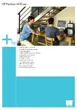
Pavilion t450.ea
Brand: HP Pages: 2
EliteDesk 800 G3
Brand: HP Pages: 11

Wind Top AE2211 series
Brand: MSI Pages: 55
eTile wt19m-fw
Brand: AOpen Pages: 28
DES4100 Series
Brand: AOpen Pages: 24


