HP Dv3-1075us - Pavilion Entertainment - Turion X2 2.1 GHz, Maintenance And Service Manual
The HP Dv3-1075us - Pavilion Entertainment - Turion X2 2.1 GHz is a powerful and versatile laptop designed for multimedia enthusiasts. Its user-friendly interface allows for seamless navigation and efficient multitasking. Unlock the full potential of this device by downloading the comprehensive user manual for free from manualshive.com.
Share
Download


Reviews:
No comments
Related manuals for Dv3-1075us - Pavilion Entertainment - Turion X2 2.1 GHz

Toughbook CF-F8EWDZZAM
Brand: Panasonic Pages: 20

Toughbook CF-T7BWATAAM
Brand: Panasonic Pages: 12

M460
Brand: Gateway Pages: 4

Chill Mat
Brand: Targus Pages: 2

Chill Mat
Brand: Targus Pages: 4

PECOS Universal
Brand: Speed Link Pages: 4

MicroSaver 2.0
Brand: Kensington Pages: 4

MT6350
Brand: media-tech Pages: 13

BUNDLES S16 OPTICAL MOUSE WIRED
Brand: PORT DESIGNS Pages: 1

LUPAUSL13E
Brand: Logik Pages: 52

SIERRA WIRELESS 250U 4G/3G LAPTOP CARD
Brand: Time Warner Cable Pages: 5

DA-71108
Brand: Digitus Pages: 9

Fieldmate Series
Brand: InfoCase Pages: 4
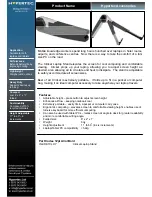
IN-CRKTCLHY
Brand: Hypertec Pages: 1
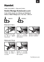
XNBLOCK200KW
Brand: Hamlet Pages: 2
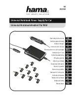
39726
Brand: Hama Pages: 22

TRI-SCREEN 2
Brand: Xebec Pages: 15
Dock II
Brand: IBM Pages: 170


