background image

 Bermuda User’s Manual

1

HP Bermuda

DDR SDRAM

200/266MHz FSB  AGP 4X

Socket A Motherboard

USER’S MANUAL

e690

Summary of Contents for Bermuda

Page 1: ...Bermuda User s Manual 1 HP Bermuda DDR SDRAM 200 266MHz FSB AGP 4X Socket A Motherboard USER S MANUAL e690 ...

Page 2: ...DDR SDRAM DDR SDRAM is the newest memory standard with the highest bandwidth and lowest latency currently available and dramatically improves the memory system s ability to service among others high multimedia requirements Universal AGP 4X Slot Supports universal AGP AGP 4X cards for high per formance component level interconnection targeted at 3D graphical applica tions supporting 133MHz 4X mode ...

Page 3: ... EPP and ECP capabilities Enhanced ACPI Anti Boot Virus Protection Programmable BIOS Flash EEPROM offering enhanced ACPI for Windows 982000 Millenium compatibility built in firmware based virus protection and autodetection of most devices for virtually automatic setup Concurrent PCI Concurrent PCI allows multiple PCI transfers from PCI mas ter busses to the memory and processor Integrated Infrared...

Page 4: ...tion Incorporates BIOS that supports autodetection of hard disk drives PS 2 mouse and Plug and Play devices to make the setup of hard disk drives expansion cards and other devices virtually automatic New Compliancy Both the BIOS and hardware levels of this motherboard meet the stringent requirements for PC 99 certification The new PC 99 requirements for systems and components are based on the foll...

Page 5: ...ltraDMA 100 is backward compatible with DMA 66 DMA 33 and DMA and with existing DMA devices and systems so there is no need to upgrade current EIDE IDE drives and host systems UltraDMA100 66 requires a 40 pin 80 conductor cable to be enabled DDR SDRAM Optimized Performance This motherboard supports a new gen eration memory Double Data Rate DDR Dynamic Random Access Memory SDRAM whichiscompatibleto...

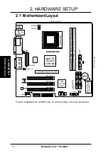
Page 6: ...DR DIMM2 64 72 bit 184 pin module 2 3 0 1 DDR DIMM1 64 72 bit 184 pin module 0 1 BERMUDA 2Mbit Flash EEPROM Programmable BIOS PRIMARY IDE PS 2 T Mouse B Keyboard AMD761 System Controller CR2032 3V Lithium Cell CMOS Power WOLCON CD AUX GAME_AUDIO Mic In Line Out Line In USB T USB1 B USB2 Top RJ 45 Socket A PCI Slot 1 PCI Slot 3 PCI Slot 2 COM2 HP USB CLR_CMOS PS_FAN ATXPWR Speaker_out CPU_FAN IR RT...

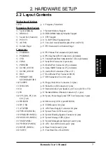
Page 7: ...ME_AUDIO p 16 Audio Port Connectors Three 1 8 8 RJ45 p 17 Fast Ethernet Port Connector RJ45 9 PRIMARY IDE p 17 IDE Connectors Two 40 1 pins SECONDARY IDE 10 FLOPPY p 18 Floppy Disk Drive Connector 34 pins 11 WOLCON p 18 Wake On LAN Connector 3 pins 12 IA p 19 InternalAudio 3 pin Speaker_out Two 4 pin CD AUX 13 IR p 19 Standard Infrared Module Connector 5 1 pins 14 SYS_FAN PS_FAN p 20 Sytem Power S...

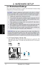
Page 8: ...to touch the IC chips leads or connectors or other components 4 Place components on a grounded antistatic pad or on the bag that came with the component whenever the components are separated from the system 5 Ensure that the ATX power supply is switched off before you plug in or remove the ATX power connector on the motherboard WARNING Make sure that you unplug your power supply when adding or re ...

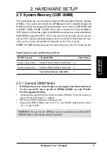
Page 9: ...he DDR memory bus runs at the same frequency as the CPU front side bus System Memory 2 H W SETUP Install memory in any combination as follows DIMM Location 184 pin DIMM Total Memory Socket 1 Rows 0 1 64MB 128MB 256MB 512MB 1GB x1 Socket 2 Rows 2 3 64MB 128MB 256MB 512MB 1GB x1 Total System Memory Max 2GB 2 5 1 General DIMM Notes DIMMs that have more than 18 chips are not supported on this motherbo...

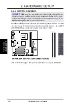
Page 10: ...ge to both your motherboard and expansion cards see 3 3 Hardware Setup Procedure for more information Insert the module s as shown Because the number of pins are different on either side of the breaks the module will only fit in the orientation shown A184 pin DDR SDRAM DIMM has a single notch slightly to the right of center BERMUDA 184 Pin DDR DIMM Sockets 0 1 0 1 BERMUDA This motherboard supports...

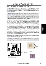
Page 11: ...er must be fully opened 90 to 100 degrees when installing or removing the CPU Insert the CPU with the correct orientation The notched corner should be oriented toward the blank space on the socket nearest the lever The CPU has a corner pin for two of the four corners and will only fit in the orientation as shown Ensure that the CPU is exactly parallel to the socket base so the pins make good conta...

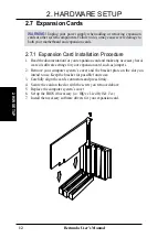
Page 12: ... for your expansion card and make any necessary hard ware or software settings for your expansion card such as jumpers 2 Remove your computer system s cover and the bracket plate on the slot you intend to use Keep the bracket for possible future use 3 Carefully align the card s connectors and press firmly 4 Secure the card on the slot with the screw you removed above 5 Replace the computer system ...

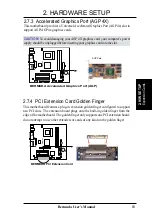
Page 13: ...aphics card into the slot 0 1 0 1 BERMUDA BERMUDA Accelerated Graphics Port AGP AGP Card 2 7 4 PCI Extension Card Golden Finger This motherboard features a plug in extension golden finger configured to support two PCI slots The extension board plugs onto the built in golden finger from the edge of the motherboard The golden finger only supports one PCI extension board do not attempt to use other e...

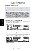
Page 14: ...floppy disk drives Check the connectors before installation because there may be exceptions IDE ribbon cable must be less than 46 cm 18 in with the sec ond drive connector no more than 15 cm 6 in from the first connector 1 PS 2 Mouse Connector Green 6 pin PS2KBMS The system will direct IRQ12 to the PS 2 mouse if one is detected If one is not detected expansion cards can use IRQ12 PS 2 Mouse 6 pin ...

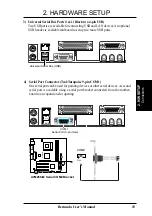
Page 15: ...o setup two more USB ports Universal Serial Bus USB 4 Serial Port Connector Teal Turquoise 9 pin COM1 One serial port can be used for pointing devices or other serial devices Asecond serial port is available using a serial port bracket connected from the mother board to an expansion slot opening COM 1 Serial Port 9 pin male Connectors 2 H W SETUP 0 1 0 1 A7M266 M A7M266 M Serial COM2 Bracket PIN 1...

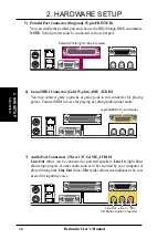
Page 16: ...E_AUDIO Line Out lime can be connected to powered speakers Line In light blue allows tape players or other audio sources to be recorded by your computer or played through the Line Out lime Mic pink allows microphones to be con nected for inputting voice Mic Line In Line Out 1 8 Stereo Audio Connectors 5 Parallel Port Connector Burgundy 25 pin PRINTER You can enable the parallel port and choose the...

Page 17: ... removed to pre vent inserting in the wrong orientation when using ribbon cables with pin 20 plugged TIP You may configure two hard disks to be both Masters with two ribbon cables one for the primary IDE connector and another for the secondary IDE connector You may install one operating system on an IDE drive and another on a SCSI drive and select the boot disk through the BIOS software IMPORTANT ...

Page 18: ... 0 1 BERMUDA BERMUDA Wake On LAN Connector IMPORTANT Requires an ATX power supply with at least 720mA 5 volt standby power WOL_CON 5 Volt Standby PME Ground Connectors 2 H W SETUP 10 Floppy Disk Drive Connector 34 1 pin FLOPPY This connector supports the provided floppy drive ribbon cable After connect ing the single end to the board connect the two plugs on the other end to the floppy drives Pin ...

Page 19: ... s SIR connector according to the pin definitions 0 1 0 1 BERMUDA BERMUDA Infrared Module Connector Front View Back View 5V IRTX IRRX NC GND IR 5V IRRX IRTX GND 1 Connectors 2 H W SETUP 12 Internal Audio Connectors 3 pin Speaker_out 4 pin CD AUX The Speaker_out connector sends a an amplified signal to headphones and pas sive audio speakers CD andAUX connectors allow you to receive stereo audio inp...

Page 20: ...s that support rotation signal outputs WARNING The CPU and or motherboard will overheat if there is no airflow across the CPU and onboard heatsinks Damage may occur to the motherboard and or the CPU fan if these pins are incorrectly used These are not jumpers do not place jumper caps over these pins 0 1 0 1 BERMUDA BERMUDA 12 Volt Cooling Fan Power SYS_FAN GND 12V GND Rotation 12V CPU_FAN PS FAN G...

Page 21: ... power supply The plug from the power supply will only insert in one orientation because of the different hole sizes Find the proper orientation and push down firmly making sure that the pins are aligned IMPORTANT Make sure that yourATX power supply can supply at least 10mA on the 5 volt standby lead 5VSB You may experience difficulty in power ing ON your system if your power supply cannot support...

Page 22: ...se This 2 pin connector seetheprecedingfigure connectstothecase mountedsuspendswitch 22 ATX Power Switch Soft Off Switch Lead 2 pin PWR The system power is controlled by a momentary switch connected to this lead Pushing the button once will switch the system between ON and SLEEP or ON and SOFT OFF depending on your BIOS or OS setting Pushing the switch while in the ON mode for more than 4 seconds ...

Page 23: ...endisabled anyonemayaccessallBIOS Setupprogramfunctions Whenenabled theSupervisorpasswordisrequiredforentering the BIOS Setup program and having full access to all configuration fields Forgot the Password If you forgot the password you can clear the password by erasing the CMOS Real Time Clock RTC RAM TheRAMdatacontainingthepasswordinformationispoweredbythe onboard button cell battery To erase the...

Reviews: