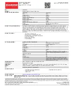
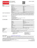
HP A4979A, Installing
The HP A4979A user manual is your essential guide to successfully installing and operating this product. With easy-to-follow instructions, you can conveniently download the manual for free from our website. Ensure a seamless setup and usage experience by accessing the comprehensive manual at manualshive.com.
Share
Download


Reviews:
No comments
Related manuals for A4979A

S15
Brand: IBM Pages: 22
DT3162
Brand: Data Translation Pages: 64
T221
Brand: IBM Pages: 38

Topaz
Brand: Rastergraf Pages: 169
ImageDP4
Brand: Datapath Pages: 2

CHROME 400 Series
Brand: S3 Graphics Pages: 67
GV-N275UD-896H
Brand: Gigabyte Pages: 32

BP-VG2080RD-A2
Brand: Bitspower Pages: 5

RX2400PRO-TD256EH
Brand: MSI Pages: 2

Discovery-III XC3S200F
Brand: Apex Instrument Pages: 18
Radeon X1650PRO
Brand: Diamond Multimedia Pages: 1

Millennium II
Brand: Matrox Pages: 24
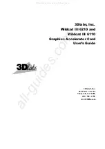
Wildcat III 6210
Brand: 3Dlabs Pages: 56

PVS-6000
Brand: Barco Pages: 2
SKU 4670PE31GDT
Brand: Diamond Multimedia Pages: 1
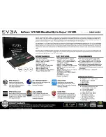
GeForce GTX 580 Classified Hydro Copper 3072MB
Brand: EVGA Pages: 1

Duros
Brand: Rastergraf Pages: 169
Intense 3D 100
Brand: Intergraph Pages: 26


