background image

-

-

., 

HEWLETT 
PACKARD 

HP  7475A 

Graphics  Plotter 

Summary of Contents for 7475a

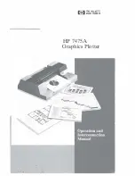
Page 1: ... FliOW HEWLETT PACKARD HP 7475A Graphics Plotter ...

Page 2: ...OPERATION HP 7475A AND Graphics Plotter INTERCONNECTION MANUAL ...

Page 3: ... and Appendix A 4 Check with your software vendor for help Your Dealer If you still have difficulty begin by contacting the person from whom you purchased your HP 7475A graphics plotter Your sales representa tive is familiar with your needs equipment and software and should be able to provide you with the information you want HP 7475A Graphics Plotter Customer Assist If you don t get the answer to...

Page 4: ...__ __ _ Identify what cable you are using by part number and where you purchased it ________ ____ _ _______ ___ Identify the type of interface option on your plotter RS 232 C or HP IB _______ _ __ __ _ ____ ___ __ _ ___ _______ ___ _ _ _ _ Identify the software name and version you are currently using __ The HP 7475A Assist service is available from 7 am 4 pm Mountain Standard Time Monday through ...

Page 5: ...otterOperation 2 1 Introduction 2 1 Major Feature Locations 2 1 Introduction to ProgrammingLanguages 2 2 WhatIs a Program 2 2 WhatProgramming LanguagesDoIUse 2 3 AGL A Graphics Language 2 3 HP GL Hewlett Packard Graphics Language 2 3 Introduction to the Plotter Coordinate System 2 4 Coordinate SystemOrientation 2 5 Hard Clip Limits 2 5 The Scaling Points PI andP2 2 7 HP GL Scaling 2 7 AGL Scaling ...

Page 6: ...ace 3 4 AT T PC 6300 COMPAQ DESKPRO and HP V ectra ES 12 QS 16 and RS 20 IBM AT PC PC XT and PS 2 Interconnection Instructions 34 Testing Communication without BASIC 3 5 Testing Communication with BASIC 3 6 Apple IIe or II Plus Computer RS 232 C Interface 3 7 Interconnection Instructions 3 7 Running the Test Program 3 9 Apple lIe or 1I Plus Computer HP IB Interface 3 10 Interconnection Instruction...

Page 7: ...structions 3 22 Running theTestProgram 3 24 HP TouchscreenPersonal Computer HP 150 HP IBInterface 3 25 InterconnectionInstructions 3 25 Running theTestProgram 3 26 Chapter4 SelectingMedia Pens andInk 4 1 WhatKind ofOutput DoYouNeed 4 1 UnderstandingMedia 4 2 ChartPaper 4 2 GlossyPresentationPaper 4 2 OverheadTransparencyFilm 4 3 Double MattePolyesterFilm 4 3 UnderstandingPens andInks 4 3 Fiber Tip...

Page 8: ...f i oil I V J ...

Page 9: ...you to verify that your plotter has not been damaged in shipment and that it is compatible with the power available in your geographic area It explains each control and indicator the plotter s coordinate system and how to set up the plotter and run the built in demonstration plot Additional information is given to show you how to connect the plotter with many commonly used computers Ail plotters a...

Page 10: ...and the instrument should be in good operating order Carefully inspect the plotter and accessories for any physical damage sustained in transit Notify the nearest HP Sales and Support Office or authorized HP dealer and file a claim with the carrier if the unit is received in a damaged condition Please check to ensure that you have received all of the items that should accompany the plotter Refer t...

Page 11: ...Cables brochure shipped with your plotter Item Part Number Service Manual 07475 90000 Interfacing and Programming Manual 07475 90001 Carrying case not suitable for shipping plotter 07475 60001 Transit case suitable for shipping plotter 1540 0061 Dust cover 07475 60010 Standard digitizing sight 09872 60066 Slanted digitizing sight 07585 60191 Special Y cable used to connect an option 001 17455A plo...

Page 12: ...um Line Current Consumption Line Voltage Selection 100V 5 100 0 120V 5 100 0 220V 5 10 240V 5 10 48to 66 Hz single phase 480mA 100V 400mA 120V 220mA 220V 200mA 240V 35 Watts maximum The 7475Ais shipped from the factory with the line voltage set to the nominal value for the area specified as the shipment s destination The voltage selected for the plotter is identified in the recessed window on the ...

Page 13: ...es and fuse caps appropriate to the plotter shipment desti nation are installed at the factory U S fuses are 4 X 1 inches and use HP 2110 0565 fuse caps European fuses are 5 X 20 millimetres and use HP 2110 0567 fuse caps Grounding Requirements To protect operating personnel the plotter must be properly grounded The plotter is equipped with a three conductor power cable which when connected to an ...

Page 14: ...20 1378 125 V IS A 1 plug rating For use in Canada Japan Mexico Philippines Taiwan UL approved in United States HP Part Number 8120 0698 250 V IS A 1 plug rating UL approved in United Stares HP Part Number 8120 2104 250 V 10 A 1 plug rating For use in Switzerland HP Part Number 8120 2956 250 V 10 A I plug rating For use in Denmark NOTE All plugs are viewed from connector end L Line or Active Condu...

Page 15: ...dically Cleaning intervals are determined by the type of operation local air contamination and climatic conditions Cleaning procedures should include the following L Blow away dust accumulation in the grit wheel area with corn pressed air if available or brush away dust using the grit wheel brush Part No 8710 1386 2 Clean the outer surface of the plotter with a damp sponge or cloth Use a mild clea...

Page 16: ... is being returned to Hewlett Packard for service contact your nearest HP Field Repair Center for complete shipping instructions In countries without Field Repair Centers contact your HP Sales and Support Office You can help assure effective servicing of your plotter by following these guidelines 1 Follow the maintenance procedures outlined in this manual to verify the malfunction and if possible ...

Page 17: ... sales slip or other proof ofpurchase to establish the warranty coverage period e Serial number of your plotter located on rear panel 3 Include your name and address Also include the telephone number where you may be reached during the day 4 Do not include the power cord or other operating accessories with your plotter unless the problem relates to an accessory OWNER S INFORMATION 1 9 ...

Page 18: ......

Page 19: ...limit of the drawing range The pen carousel is located on the left side of the plotter and holds up to six pens which can be accessed by the pen holder The pinch wheels and grit covered drive wheels that move the paper back and forth across the platen are spaced to accommodate either ANSI A and B or ISO A4 and A3 size media The paper loading lever which raises and lowers the pinch wheels is locate...

Page 20: ...on to Programming Languages What Is a Program A program is an organized set of instructions that tells your computer and plotter to accomplish certain tasks There are two types of programs that you can use to generate the input data for your graphics plots prepackaged software programs and user written software programs Prepackaged software programs are easy to use and usually do not 2 2 PL01 1 ER...

Page 21: ...computer your computer programming manual contains com plete details of the BASIC language version that it implements In addition to the computer language you must also understand the plotter s language HP GL or a high level graphics programming lan guage such as AG1 AGL A Graphics Language AGL is implemented on Hewlett Packard computers to simplify graphics plotting AGL statements are an extensio...

Page 22: ...s coordinates with respect to the origin point X 0 Y 0 For example the coordinates X 4and Y 5 define the point at the inter section of the fourth positive grid line along the X axis and the fifth positive grid line along the Y axis These coordinate values are used as parameters in HP GL instructions to move the pen to any given point in the plotting area Grid spacing resolution can be in either pl...

Page 23: ...ints PI and P2 can be positioned Except for narrow margins which are required by the grit wheel paper moving technology the hard clip limits allow plotting on the entire paper surface The following table shows the maximum plotting range in plotter units for aB four paper sizes Note that the plotting ranges in the X and Y axis are reversed when the 90 degree rotate function is turned on Refer to Ro...

Page 24: ...ngs Plotter Vnits Selected VS MET A4 A3 Paper Size X Axis V Axis US A4 A 0 10365 0 7962 8 5 x 11 in 257 8 mm 198 1 mm 10 15 in 7 8 in US A3 B 0 16640 0 10365 11 x 17 in 413 9 mm 257 8 mm 16 3 in 10 15 in MET A4 A4 0 11 040 0 7721 210 X 297 mm 274 6 mm 192 1 mm 10 81 in 7 56 in MET A3 A3 0 16158 0 11 0 40 297 X 420 mm 401 9 mm 274 6 mm 15 82 in 10 81 in 2 6 PLOTTER OPERATION ...

Page 25: ... I and P2 can be used in conjunction with the Hp GL instruction se to enable you to plot in user units that are convenient to your application The size of the user unit is determined by the phys ical dimensions of the P lIP2 f rame and by the parameters of the se instruction These parameters assign user unit coordinates to PI and P2 and divide scale the entire plotting area not just the PlIP2 fram...

Page 26: ...ftware hard clip plotting limits the shortest side is scaled from 0 to lOO G nUs graphic display units The longest side is scaled from 0 to lOO G nUs times the ratio of the longest side divided by the shortest side Thus a square plotting area will have lOO G nUs in each direc tion but if the plotting area is twice as long in one direction as the other the longest side will have 200 G nus In this c...

Page 27: ...ocedure can be used for manually relocating PI a d P2 NOTE Always set PI first since P2 moves when PI is moved 1 Using the cursor pushbuttons arrow pushbuttons position the pen at the new location chosen for PI 2 Press ENTER simultaneously with P1 to store the new location of PI 3 Using the cursor pushbuttons position the pen at the location chosen for P2 4 Press ENTER simultaneously with P2 to st...

Page 28: ...ture is illus trated as follows DETAIL A Illustrates the initial PlIP2 frame DETAIL B Illustrates moving PI to a new position P2 moves propor tionately until the hard clip limit is reached At this poin1 P2 stops moving with PI and the distance between PI and P2 changes DETAIL C Illustrates moving PI back to its original location PI and P2 maintain the relationship established in Detail B thus prod...

Page 29: ...DETAIL A DETAIL 8 DETAIL C NEW Pl LOCATION 2 2 HAAD CLlP LIMITS HAAD ClIP LIMITS OLD Pl LOCATION o HAAD CLlP i LIMITS Squeezing The Scaling Area PLQITER OPERATION 2 11 ...

Page 30: ...g the HP GL instruction RO The only difference is the rotated locations UR Ll O O OAIGIN r pi1 I I I _ HARD I CLIP_ I LIMITS I I I INPUT I Pt I WIN DOW _ _ _ _ _ _ _ _ _ _ _ _ _ _ _ J LL 0 0 ORIGIN DEFAULT ORIENTATION r I Pt I I I I I I I I r Y I I x P2 I L _ _ _ _ _ _ _ _ _ _ _ _ _ oI UR ROTATED 90 DEGREES Front Panel Rotation on AIA4 Size Paper LL 0 0 ORIGIN fp I I I I I I I I I I I I I 1 HARD y...

Page 31: ...limits as shown in the following illus tration The default input window is also rotated but its physical size is clipped to a square area by the hard clip limits Note that the input window limits programmed pen motion to the window area but the pen can still be moved anywhere within the hard clip limits using the front panel cursor buttons The input window can be expanded to the hard clip limits a...

Page 32: ...ith a running program This interac tion includes entry of digitized points pen selection and program suspension without loss of data All front panel controls are common to both Hp JB and RS 232 C interface options Configuration controls consist of two switches on the rear panel These switches determine the power up default paper size hard clip limits and PI P2 coordinate values The switches are co...

Page 33: ...N UfD SIZE D D 741 1 PLOTTER W WUYT C O VIEW A I O FRONT PANEL 2 10 REAR PANEL 14 19 RS 232 C CCITT V 24 f 1 U II h 4 ft9 21 l c eCttTy U I REAR PANEL 20 22 HP IB f Operator Controls 1 2 PLO I ER OPERATION 2 15 ...

Page 34: ...but maintains any pre viously set PI P2 coordinate values b Cancels any pending error ERROR light blinking due to having received a move command with the pinch wheels up NOTE If an 110 error or an HP GL error other than number 8 is set the ERROR light will continue blinking P1 P2 Pressing P1 or P2 causes the plotter to raise the pen and move it to the current coor dinate location of scaling point ...

Page 35: ...EN pushbutton causes the plotter to store its cur rent pen into the corresponding numbered carousel position if possible If the selected carousel position is occupied the plotter stores its current pen into the lowest numbered empty position if any The pen holder then returns to its previous location ERROR This multi purpose ERROR light can be off on or blinking as follows a When the ERROR light i...

Page 36: ...ys on these lights also serve as power on indicators Also note that the current paper size light will blink whenever the plotter receives the HP GL instruction DP This indicates a point can he digitized using the ENTER pushbutton SIZE Pressing the SIZE pushbutton simul taneously with the ENTER pushbutton selects the alternate paper size The following actions occur each time a new paper size is sel...

Page 37: ...s pressed in conjunction with any cursor pushbutton cursor speed is four times greater d Pressing FAST by itself pauses plotting as long as the pushbutton is held down NOTE Pressing any cursor pushbutton during plotting will pause the plot and perform the appropriate cursor motion Plotting will resume at the new location when the cursor pushbutton is released ENTER This multi purpose pushbutton is...

Page 38: ...serv motors become inoperative and the ERROR light starts blinking In this case the plotter will not respond to ENTER VIEW or any other front panel control The only way to correct this situation is to remove the obstruction and cycle the LINE switch to OFF then ON again ENTER digitizing The current paper size light e A3 or AlA4 will blink when the plotter receives the HP CL instruction DP This bli...

Page 39: ...dd parity 0 establishes even parity DIY This rocker switch is used to establish either programmed on or programmed off operation status when the plotter is turned on Position D is used when the plotter is directly connected to a computer endline operating environment In this position the plotter powers up in the programmed on operating state The plotter will respond to all HP GL and escape sequenc...

Page 40: ...aper size Combination switch settings of the US MET and A4 A3 switches are as follows Combination Selected Default Switch Settings Paper Size US A4 ANSI A US A3 ANSI B MET A4 ISO M MET A3 ISO A3 After power is turned on paper size can be toggled between A and B or A4 and A3 sizes using the front panel ENTER SIZE pushbuttons BAUD These four rocker switches are used I to select a baud rate which cor...

Page 41: ...al description ADDRESS These five rocker switches are used to establish the plotter address value The plotter address is selected by setting each switch to the appropriate binary bit position defined in the following table The plotter is set to an address code of 05 at the factory This corresponds to a listen character of and a talk character of E The plotter is in listen only mode when all five s...

Page 42: ...1 2 3 4 6 7 10 1 1 12 13 14 15 16 17 20 21 22 23 24 r I 5 U 1 0 1 0 1 21 25 L _ _ _ _ _ _ _ _ _ _ _ _ _ _ _ _ _ _ _ _ _ __ _ _ _ 1 6 V 1 0 1 1 0 22 26 7 W 1 0 1 1 1 23 27 8 X 1 1 0 0 0 24 30 9 Y 1 1 0 0 1 25 31 Z 1 1 0 1 0 26 32 1 1 0 1 1 27 33 1 1 1 0 0 28 34 J 1 1 0 1 29 35 1 1 1 1 0 30 36 r L 1 1 1 1 31 37 j Setting Up the Plotter preset Reserved for HP Desktop Computer Address Sets Listen only...

Page 43: ...ading Pens and the Carousel The following procedure describes how to load pens into the carousel and how to load thecarousel into the plotter 1 Select the pen type and pen colors to be loaded into each position of the carousel One or more ofthe pen positions may be used 2 Uncap and load each pen into the carousel as follows Refer to the following photographs a Hold the carousel and depress the pen...

Page 44: ...respond with the paper size being used Combination Selected Default Switch Settings Paper Size US M ANSI A US A3 ANSI B MET A4 ISO A4 MET A3 ISO A3 NOTE The positions of the US MET and M A3 switches are checked by the plotter only when power is first turned on or when a front panel reset is invoked using the ENTER VIEW pushbuttons After power is turned on paper size can be toggled between A and B ...

Page 45: ...aps the pen to avoid getting ink on the new paper 4 Lay a sheet of paper on the platen surface so the paper is aligned with the paper guide the white line at the left rear of the platen and the left edge of the platen A and A4 size paper are loaded with the long side horizontel B and A3 size paper are loaded with the long side vertical Refer to the following illustration 5 Move the paper loading l...

Page 46: ...c power is applied The initialization cycle sets all plotter functions to their default condi tions conditions assumed by the plotter in the absence of an actual instruction Apply power to the plotter as follows 1 Using the power cord supplied connect the plotter to a grounded three wire ac outlet 2 28 PLOTTER OPERATION ...

Page 47: ... Manual for the explanation of each function After power up initialization is completed the first pen select command will cause the carousel to be initialized The pen select command can be invoked programmatically with an Hp GL command or manually with the PEN pushbuttons Carousel initialization consists of backing the carousel around to its stop before it is advanced to the position that correspo...

Page 48: ...5 of P2y Ply for X tick Mask value IM223 0 0 All errors recognized no service request and no parallel poll response Fill type FT Type I solid bidirectional shading Fill spacing FT 1 of the diagonal distance betwc Cn PI and P2 used only for fill type 3 or 4 Fill angle FT O degree Pen thickness PT 0 3 mm fill spacing for solid fill types I and 2 Label origin Current pen location Relative character D...

Page 49: ... demonstration plot does not exclude all possible failures it does serve as a confidence test since the probability is very high that the plotter is operating properly The demonstration plot is performed as follows 1 Load A or A4 size paper and a full carousel into the plotter The carousel may be filled with any combination of pens However the pen widths and colors shown in the f ollowing table ar...

Page 50: ...Floltt pt ratiol1 6 GRAPH I C S I MPROVES COMMUN I CA T I O N b l t 1 SALES REVENUE DI STR IBUTI ON 0 2500 tr l 0 Z l 2000 D I V 12 3 0 00 1500 MANF 38 o 3 0 D I VIDEND H I STORY 1000 500 o YEARS ...

Page 51: ...NOTES ...

Page 52: ......

Page 53: ...here is a good possibility that it still can be interfaced to the HP 7475A First determine which kinds of commu nication interfaces are available for your computer If your computer supports an RS 232 C CCITI Y 24 interface or an ANSVIEEE 488 1978 HP IB interface then it probably can be interfaced to an HP7475A IWad the manual that describes the communications eqnip ment for your computer and then ...

Page 54: ...he program to work with substitute software read the software manual paying particular attention to the sections dealing with programming the communications hardware There are usually two parts to this type of program opening the com munications port and writing to the communications port Opening the communications port may require specifying a number of interface parameters such as baud rate pari...

Page 55: ... paper is properly loaded and the VIEW pushbutton has not been pressed Are you using the proper operating system and programming language Check to see if you are using the operating system andlor program ming language listed in each instruction set If you are still having problems contact your salesperson Your sales person will probably be able to help solve your problem or refer you to someone wh...

Page 56: ...ale connector with the HP 2454lA dual serial card using 25 pin female connector Interconnection Instructions 1 Turn offyour plotter and computer equipment Cable HP l7255D HP 24542G HP 24542G HP l7255M or HP 13242G 2 If necessary install the serial interface card Refer to your com puter documentation for details If you installed a serial card go to step 3 NOTE If you have more than one serial port ...

Page 57: ...A AND A4 PAPER I OR TO A3 FOR 8 AND A3 PAPER ti Z m il ii SET 84 AND 82 TO AND 83 AND I 0 tu L I PARITY L BAUD seT Sl TO 0 FOR B1 TO 0 FOR 9600 BAUD RATE NO PARITY SETTING SET TO POSITION D FOR ENDUNE OF 82 18 IRRELEVANT OPERATING ENVIRONMENT 4 Connect the plotter to the computer The following illustration shows an HP Vectra PC Be sure you are using the correct cable for your computer and plotter ...

Page 58: ...pen to the carousel Testing Communication with BASIC To test the computer plotter interface turn on your computer and plotter load pens and paper then follow these steps 1 At the DOS prompt type the following substitute COM2 for COM1 if necessary and press ENTER MODE COM1 9600 N 8 1 P This sets the RS 232 C port for 9600 baud no parity 8 data bits one stop bit and continuous error checking 2 Enter...

Page 59: ...l Card as follows refer to your com puter documentation for details a Set the two banks of switches on the serial card as shown here 1 2 3 4 5 6 7 SW1 Off On Off On Off On On SW2 On Off Off On Off Off Off b With your computer unplugged install the serial card in slot 2 ofthe computer Make sure that the arrow on the card s jumper block is pointing toward the word TERMINAL PLO ITER INTERCONNECTION 3...

Page 60: ... in the following diagram Your plotter checks the switch settings only when you turn it on so be sure the plotter is turned off before changing switch settings You are not limited to a 2400 baud rate but the plotter s baud rate and the baud rate on your serial card must match SET TO US POSITION FOR A AND B r PAPER OR TO MET FOR A4 AND A3 PAPER r SET TO A4 FOR A AND A4 PAPER OR TO A3 FOR B AND A3 P...

Page 61: ...o gram Ifyou need help entering and running the program refer to your computer documentation 1 0 PR 2 IN 2 20 PRINT CHRS Z7 t M50 53 1 3 1 3 30 PRINT I N O I 40 INPUT ID 50 PRINT SPI PA500 500 50 PRINT LB ID COMMUNICATION OK CHR 3 70 PRINT PA0 0 SP0 B0 PR 0 I N 0 90 END Your plotter will select pen 1 and print 7475A COMMUNICATION OK PWITER INTERCONNECTION 3 9 ...

Page 62: ... the Apple IEEE 488 Card into Slot 3 refer to your com puter documentation for details 2 With your plotter and computer turned off connect the plotter to the computer using the HP IB cable as shown below The foIlowing illustration shows an Apple IIe MonItor power cord Video cable Computer power cord 3 10 PLOTI ER INTERCONNECTION HP IS cable Plotter power cord ...

Page 63: ...CTERS FOR LISTEN AND E FOR TALK _ _ _ _ _ _ _ SET TO A4 FOR A AND A4 PAPER OR TO A3 FOR B AND A3 PAPER Running the Test Program To test the computer plotter interface turn on your compllter and plotter load pens and paper and enter and run the following BASIC program If you need help entering and running the program refer to your computer documentation 1 0 20 30 4 0 5 0 6 0 70 80 PRo 3 I No 3 PRI ...

Page 64: ...ions 1 With your plotter and computer turned off connect the plotter to the computer using theRS 232 C and modem eliminatorcables as shown below Either end of the RS 232 C cable can be connected to the plotter Monitor power cord Video cable Apple III modem eliminator cable _ I RS 232 C cable 3 12 PLO ITER INTERCONNECTION Apple 111 power cord Plotter power cord ...

Page 65: ...l need to make a copy ofyour Apple Business BASIC disc that is not write protected a Insert the System Utilities disc Select the SYSTEM CONFIG PROGRAM then select READ A DRIVER FILE b Load the System Utilities Data disc Enter the pathname D1 RS232 DRIVER and press the RETURN key Reinsert the System Utilities disc and press the ESCAPE key c Select EDIT DRIVER PARAMETERS Then select the number cor r...

Page 66: ...To test the computer plotter interface turn on your computer and plotter load pens and paper and enter and run the following BASIC program If you need help entering and running the program refer to your computer documentation 1 0 OPEN O 1 u PLTII 20 PRINT 1 I N 5P1 PA500 500 30 PRI NT 1 LBCOMMUNI CATI ON OK CHR 3 40 PRINT 1 1 PAO O 5PO 5 0 END Your plotter will select pen 1 and print 7475A COMMUNI...

Page 67: ...tter as shown in the following illustration Your plotter checks the switch settings only when you turn it on so be sure the plotter is turned off before changing the switch settings SET S1 TO 0 FOR SET TO US POSITION FOR A AND B r PAPER OR TO MET FOR A4 AND A3 I PAPER _ _ _ _ SET TO A4 FOR A AND A4 PAPER I OR TO A3 FOR B AND A3 PAPER SET 84 TO M 1 AND 81 82 AND 83 TO MO FOR 2400 BAUD RATE NO PARIT...

Page 68: ... need help entering and running the program refer to your computer documentation 10 OPEN COMl 9600 N 8 l RS CS65535 DS CO AS U 20 PRINT tU IN OI H 30 INPUT nI 10 40 PRINT n I SPl PA500 500 50 PRINT nI LS IO PLOTTER OK CHR 3 60 PRINT n I PA0 0 SP0 70 END Your plotter selects pen 1 and prints 7475A PLOTTER OK NOTE If you are not using BASIC a plotter driver is required to run a Macintosh computer wi...

Page 69: ...42G Amiga 2000 HP 17255D Interconnection Instructions 1 With your equipment turned off use the cable to connect the plotter to the computer s serial port The following illustration shows an Amiga 2000 Computer power cord Monitor power cord VIdeo cable AS 232 C cable Plotter power cord PLCYITER INI ERCONNECTION 3 17 ...

Page 70: ...ING ENVIRONMENT 3 Turn on the plotter and boot up the Amiga using your working copy ofthe Workbench operation system 4 Run the Printer utility in the Workbench Preferences drawer refer to Commodore s Workbench documentation 5 From the Printer main menu select the Serial interface 6 Save your settings and return to the Preferences drawer 7 Set the Amiga s serial port settings as follows refer to Co...

Page 71: ...d application by double clicking on the Notepad icon 2 Type the following HP GL commands uppercase only into Notepad IN SP1 SP2 SP0 3 Select Printas Draft then Print to send the commands to the plotter The plotter should select pen 1 and pen 2 sequentiaJIy PWITER INTERCONNECTION 3 19 ...

Page 72: ...ions 1 With your plotter and computer turned off connect the plotter to the computer using the HP IB cable shown Either end of the cable can be connected to the plotter or computer The illustration below shows an HP Model 216 connected to the plotter Monitor power cord HP IB cable Computer power cord 3 20 PLOTI ER INTERCONNECTION Plotter power cord ...

Page 73: ...1EQUIVALENT TO PLOTTER ADDRESS CHARACTERS FOR LISTEN AND E FOR TALK L _ _ _ _ _ _ SET TO A4 FOR A AND A4 PAPER OR TO A3 FOR B AND A3 PAPER Running the Test Program To test the computer plotter interface turn on your computer and plotter load pens and paper and enter and run the following BASIC program If you need help entering and running the program refer to your computer documentation 1 0 OUTPUT...

Page 74: ...0 HP 13242G System with Dual Disc Drive Interconnection Instructions 1 With your plotter and computer turned off connect the plotter to port 2 of the computer using the RS 232 C cable as shown below Either end ofthe cable can be connected to the plotter or computer Computer power cord 3 22 PLOTrER INTERCONNECTION RS 232 C cable Plotter power cord ...

Page 75: ... if you have difficulty with this step a Load the MS DOS System Disc Touch DEVICE CONFIG Then touch START APPLIC to display the DEVICE CONFIGURATION screen b Touch the PLT field then use the NEXT CHOICE key to select PLT PORT 2 Next touch SAVE CONFIG c Press the USERlSYSTEM key on your keyboard twice to change the function key selections Then select CONFIG KEYS d Select the PORT 2 CONFIG field to ...

Page 76: ...eed help entering and running the program refer to your computer documentation 1 0 OPEN O I PLT 20 PRINT 1 IN O I 30 CLOSE 1 1 4 0 OPEN I 2 PLT 50 INPUT 12 ID 60 OPEN O I PLT 70 PRINT 1 1 SPl PA50 0 500 80 PRINT 1 1 LB I D COMMUN I CATION O K CHR 3 90 PRINT 1 1 PA0 0 SP 0 1 00 END Your plotter will select pen 1 and print 7475A COMMUNICATION OK 3 24 PWITER INTERCONNECTION ...

Page 77: ...or HP 150 System with Dual Disc Drive Interconnection Instructions 1 With your plotter and computer turned off connect the plotter to port 2 of the computer using the HP IB cable as shown below_ Either end of the cable can be connected to the plotter or computer Computer power cord HP IS cable Plotter power cord PLO ITER INTERCONNECTION 3 25 ...

Page 78: ...ND A3 PAPER 3 Configure your computer system as follows Referto your computer documentation ifyou have difficulty with this step a Load the MS DOS System Disc Touch DEVICE CONFIG Then touch START APPUC to display the device configuration screen b Touch the PLT field then use the NEXTCHOICE key to select PLT HP IB 5 Touch SAVE CONFlG to save the configuration c Press EXIT CONFlG key to return to P ...

Page 79: ...FOR ENDUNE OPERATING SYSTEM Set the DEC 1 00 s printer port configuration as follows Press the Set Up key then press th1 Next Screen key three times to display the Printer set up Use t e arrow keys to change the screen to read 8N DA TABIP and r6O FXMIT RCV BA UD Communication Verification Load pens and paper a d run the following MBA SIC program 1 0 LPRI NT I N 2 0 LPRINT CHR 2 7 30 LPRI NT CHR 27...

Page 80: ......

Page 81: ...ith your plotter gives part numbers and ordering information for Hewlett Packard pens and media Pens Your plotter can use fiber tip paper pens transparency pens and short body refillable drafting pens Fiber tip paper and transparency pens are available in vivid matching colors for duplicating paper and overhead graphics The following table describes each pen type Pen Type Fiber tip paper Fiber tip...

Page 82: ...stored in a honwntal position Symptoms and Solutions Drafting pens provide the highest quality lines available on the plotter If you are not getting the quality of output you desire consult the following table It will help you diagnose and correct output problems Symptoms and Solutions Problem Possible Cause Pen does not Pen is clogged write Cleaning wire is bent Beginning ofa Ink is starting to l...

Page 83: ...lm surface is Use HP film abrasive Pen tip is Ifthe tip is not damaged centered replace it Plotter may need If wavy lines are adjustment not caused by a damaged pen contact an HP servIce representative Pen is dirty Clean the pen Ink flow is Reduce pen speed insufficient or use thinner ink Pen is dirty Clean the pen Pen speed is too Reduce pen fast speed Pen is running Refill the out ofink reservoi...

Page 84: ...ilm Paper backing protects film during plotting Double matte Finely coated and translucent Good for high polyester film accuracy applications and archive storage Dimensionally stable Expensive Film ofstandard thickness 3 mil is recommended for best results Handle your plotting media by the edges when preparing final plots Oil from fingerprints can prevent ink from adhering to the medium Plotting m...

Page 85: ...ssy Ex cellent Plotter Paper qualityfor presenta ti ons reports and han d ou ts V ivid pro fess ional resu l ts 1 0 c m Transparency N ot Plotter Film r ecommend ed Double matte Not Polyester r ecomm ende d Film Fiber tip Transparency Drafting Pens Pens Not N ot r ecomm ende d reco mm ende d Go od q uali ty N ot 1 0 c m s reco mm end e d Ex ce llent N ot q uality for reco mm end e d overhea d pres...

Page 86: ...NOTES ...

Page 87: ...hrough a sta n dard 25 pin fema l e connector Conn ector pin allocatio n s ar e iden ti fi ed an d describedin the followi ng tab l e Wire Signal Name Pin RS 232 C CCITT Y 24 Protec ti ve Gro un d 1 AA 101 Tran smittedData 2 BA 103 ReceivedData 3 BB 104 Reque st toS e n d 4 CA 105 Clear toS e n d 5 CB 106 DataSetR e ady 6 CC 107 Signa l G ro u n d 7 AB 102 Data CarrierD et e ct 8 CF 109 S eco n da...

Page 88: ...e 25 pin HP Part Number Plotter End Computer End 17255D male female 17255M or 13242G male male r 1 I e 3 2 f r 2 3 I e 7 7 f r 20 S I e s 6 f r 6 20 Symmetrical either end may be connected tothe plotter Other pins are connected in the 13242G but do not affect plotter operations A 2 RS 232 C INTERFACING ...

Page 89: ...Connector Type HP Pari Number Plotter End Computer End 17302A male 25 pin male 8 pin mini din 20 2 3 3 2 5 4 7 8 RS 232 C INTERFACING A 3 ...

Page 90: ...pe 25 pin HP Part Number Plotter End Computer End 173550 male female 17355M male mate 1 T 1 2 2 I 3 I 3 I I I I I I I I I I I I 25 j 25 Symmetncal either end may be connected to the plotter A 4 RS 232 C INTERFACING ...

Page 91: ...pe 25 pin Plotter End male Computer 1 31 2 1 7 1 1 _ 1 5 I r3 1 21 71 T5 Terminal Computer End male computer female terminal 6 1 8 1 6 I 8 I T IIIII I I IIII 25 25 pins 4 5 6 and 8 through 25 are directly connected between the computer and lerminal connectors ilS 232 C INTER ACING A 5 ...

Page 92: ...tter End Computer End 24542G male 25 pin female 9 pin 4 1 r 2 2 r 3 3 r 5 4 L 6 7 5 r r 20 6 L re r s 7 Connector Type HP Part Number Plotter End Computer End 92219M male 25 pin male 9 pin 1 1 7 3 3 5 20 7 2 9 A 6 RS 232 C INTERFACING ...

Page 93: ... 2 22 switch settings 2 23 C Carousel initialization and 2 29 loading the 2 25 2 26 removing the 2 25 Cartesian coordinate system 2 4 Cleaning pen carousel 1 8 plotter 1 7 1 8 Commodore CBM 8032 Computer HP IB plotter and 3 24 3 25 Confidence test see Demonstration plot Configuration system 3 2 Controls configuration 2 14 front panel see Front panel interface 2 14 Coordinate system Cartesian see C...

Page 94: ... Power up Demonstration plot 2 31 2 32 Digitizing 2 20 Documentation plotter 1 1 e Eavesdrop operating environment 2 21 Endline standalone operating environment 2 21 Enter pushbutton digitizing and the 2 20 Fast pushbutton interaction with 2 22 paper size lights and 2 18 Paper Size pushbutton interaction with 2 19 2 22 2 26 Pen pushbuttons interaction with 2 20 Setting P1 P2 and the 2 16 2 20 usin...

Page 95: ...tt Packard Graphics Language definition of 2 3 scaling and 2 7 HP IB Hewlett Packard Interface Bus Option 002 address switches and positions 2 23 2 24 3 4 listen oniy mode and 2 23 US MET switch and 2 23 Hard elip limits _ 2 5 1 IBM Personal Computer AT PC PC XT and PS 2 3 4 3 6 Indicators front panel see Front panel Initialization see Carousel Paper Plotter Input window 2 5 2 18 Inspection initia...

Page 96: ...ng ranges see Plotting ranges Media see also Paper choosing the correct 2 25 4 1 loading 2 26 2 28 pens and see Pens selecting 4 1 4 5 size switches 2 22 switch settings and 2 26 n Numeric range maximum 2 5 o Option 001 see RS 232 C Option 002 see HP IB P P1 P2 positions see also Scaling Points automatic postioning and 2 9 default positions for 2 9 Enter pushbutton and 2 9 2 16 PlIP2 pushbuttons d...

Page 97: ...rafting 4 1 4 5 fiber tip paper 4 1 4 5 loading 2 25 2 26 media and 4 5 pushbuttons for 2 17 2 29 selecting 4 1 4 5 symptoms and solutions for 4 2 4 3 transparency 2 25 4 1 4 4 types of 2 25 4 1 Pinch wheel positioning the 2 26 2 27 Plots preparing equal sized 2 9 2 10 Plotter address 2 23 2 24 3 4 controls and indicators 2 14 2 20 coordinate system see Coordinate system default conditions 2 30 do...

Page 98: ...ever and 2 28 plotter 2 28 Power input socket 2 21 Program definition of 2 2 2 3 Programmed on offstates 2 21 Programming language s AGL see AGL selecting a 2 3 HP GL see HP GL introduction to 2 2 2 4 Pushbuttons Enter 2 19 2 20 Fast 2 19 P1 P2 2 16 Pen 2 17 Pen UID 2 18 Size 2 18 View 2 19 r RS 232 C cable Pin allocations A I Schematics A 2 A6 RS 232 C interface Option 01 2 21 2 22 Rear Panel fea...

Page 99: ...tons and _ _ 2 9 setting the _ _ 2 9 Setting up the plotter see Plotter Shipping the plotter _ _ _ _ 1 8 1 9 Size pushbutton using the _ 2 18 Stand alone operating environment _ _ _ 2 21 Supplies ordering _ 1 3 4 1 Symptoms and solutions see Pens U US MET switch _ _ _ 2 22 2 26 User units 2 4 V View pushbutton error light and 2 19 using the 2 19 Voltage selecting 1 5 x X axis 2 4 y Y axis 2 4 SUBJ...

Page 100: ...NOTES ...

Page 101: ...F n HEWLETT a e PACKARD 11111111111111111 11111 11111111111111111111 Manual Part Number 07475 90002 Printed in U S A September 1990 ...

Reviews: