background image

HP 250 G6 Notebook PC

Maintenance and Service Guide

Summary of Contents for 250 G6

Page 1: ...HP 250 G6 Notebook PC Maintenance and Service Guide ...

Page 2: ...umber 926816 001 Product notice This guide describes features that are common to most models Some features may not be available on your computer Not all features are available in all editions or versions of Windows Systems may require upgraded and or separately purchased hardware drivers software or BIOS update to take full advantage of Windows functionality Windows 10 is automatically updated whi...

Page 3: ... another hard surface such as an adjoining optional printer or a soft surface such as pillows or rugs or clothing to block airflow Also do not allow the AC adapter to contact the skin or a soft surface such as pillows or rugs or clothing during operation The device and the AC adapter comply with the user accessible surface temperature limits defined by the International Standard for Safety of Info...

Page 4: ...iv Safety warning notice ...

Page 5: ... 23 Cables 24 Mass storage devices 25 Miscellaneous parts 26 4 Removal and replacement procedures preliminary requirements 27 Tools required 27 Service considerations 27 Plastic parts 27 Cables and connectors 27 Drive handling 28 Grounding guidelines 28 Electrostatic discharge damage 28 Packaging and transporting guidelines 29 Workstation guidelines 29 5 Removal and replacement procedures for Cust...

Page 6: ...7 Heat sink assembly 59 TouchPad button board 63 System board 64 Display assembly 66 Power connector cable 76 Power button board 77 Cable locations 78 Top cover keyboard 79 7 Computer Setup BIOS TPM and HP Sure Start 81 Using Computer Setup 81 Starting Computer Setup 81 Using a USB keyboard or USB mouse to start Computer Setup BIOS 81 Navigating and selecting in Computer Setup 81 Restoring factory...

Page 7: ...ition select products only 90 9 Using HP PC Hardware Diagnostics UEFI 91 Downloading HP PC Hardware Diagnostics UEFI to a USB device 91 10 Specifications 93 Computer specifications 93 39 6 cm 15 6 in display specifications 94 Hard drive specifications 95 M 2 solid state drive specifications 96 DVD RW SuperMulti DL Drive specifications 97 11 Statement of memory volatility 99 Nonvolatile memory usag...

Page 8: ...viii ...

Page 9: ...l Celeron N3060 1 6 GHz turbo up to 2 48 GHz 2 MB L3 cache 1600 MHz dual 6W Graphics Internal graphics Intel HD Graphics 620 Intel HD Graphics 520 Intel HD Graphics 405 Intel HD Graphics 400 Switchable discrete graphics AMD Radeon M520 R17M M1 30 with 2048 MB of dedicated video memory Support HD Decode DX12 and HDMI Panel 39 6 cm 15 6 in high definition HD white light emitting diode WLED SVA anti ...

Page 10: ...mory 4096 1 2048 MB total system memory 2048 1 Hard drives Supports 6 35 cm 2 5 in SATA hard drives in 9 5 mm 37 in and 7 2 mm 28 in thicknesses Support for m 2 SATA SSD Single hard drive configurations 1 TB 5400 rpm 9 5 mm or 7 2 mm 500 GB 5400 7200 rpm 7 0 mm eMMC configurations 128 GB M 2 SATA 3 configurations value 256 GB 128 GB M 2 SATA 3 configurations TLC 512 GB 256 GB 128 GB Optical drive ...

Page 11: ...ices Support for the following WLAN formats Intel Dual Band Wireless AC 3168 802 11 ac 1x1 WiFi BT 4 2 Combo non vPro Intel Dual Band Wireless AC 7265 802 11AC 2x2 WiFi BT 4 2 Combo Adapter non vPro External media card HP Multi Format Digital Media Reader Support SD SDHC SDXC Push pull insertion removal Internal Card One M 2 slot for SSD One M 2 slot for WLAN Ports VGA Dsub 15 pin supporting 1920 ...

Page 12: ...curity Lock Operating system Preinstalled Windows 10 Windows 10 Professional For Developed Market ML Windows 10 Home ML Windows 10 Home Plus ML Windows 10 Pro StF MSNA Standard For Emerging Market EM SL Windows 10 Home EM SL Windows 10 Home Plus EM SL Windows 10 Pro StF MSNA Strategic Windows 10 Pro StF MSNA Value EM Windows 10 Pro StF MSNA Standard For China Market CPPP Windows 10 Home High End C...

Page 13: ...Category Description 7th gen Dis 7th gen UMA 6th gen Dis 6th gen UMA Pen Cel UMA Battery Optical drive 5 ...

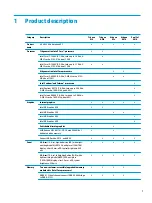
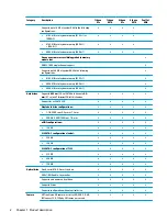
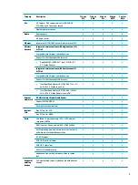
Page 14: ...6 Chapter 1 Product description ...

Page 15: ... connectors facing the computer 2 Insert the card into the memory card reader and then press in on the card until it is firmly seated To remove a card Pull the card out of the memory card reader 4 USB 2 0 port Connects a USB device such as a cell phone camera activity tracker or smartwatch and provides data transfer 5 Optical drive select products only Depending on your computer model reads an opt...

Page 16: ...on and off during routine operation 4 External monitor port Connects an external VGA monitor or projector 5 RJ 45 network jack status lights Connects a network cable White left The network is connected Amber right Activity is occurring on the network 6 HDMI port Connects an optional video or audio device such as a high definition television any compatible digital or audio component or a high speed...

Page 17: ... refer to the Regulatory Safety and Environmental Notices To access this guide 1 Type support in the taskbar search box and then select the HP Support Assistant app or Click the question mark icon in the taskbar 2 Select My PC select the Specifications tab and then select User Guides NOTE When a device is connected to the jack the computer speakers are disabled Left 9 ...

Page 18: ... 4 Internal microphone Records sound The antennas are not visible from the outside of the computer For optimal transmission keep the areas immediately around the antennas free from obstructions For wireless regulatory notices see the section of the Regulatory Safety and Environmental Notices that applies to your country or region To access this guide 1 Type support in the taskbar search box and th...

Page 19: ...ad zone Reads your finger gestures to move the pointer or activate items on the screen 2 Left TouchPad button Functions like the left button on an external mouse 3 Right TouchPad button Functions like the right button on an external mouse Keyboard area 11 ...

Page 20: ...hts Component Description 1 Caps lock light On Caps lock is on which switches the key input to all capital letters 2 Mute light Amber Computer sound is off Off Computer sound is on 12 Chapter 2 Components ...

Page 21: ...ton briefly to exit Hibernation CAUTION Pressing and holding down the power button results in the loss of unsaved information If the computer has stopped responding and shutdown procedures are ineffective press and hold the power button for at least 5 seconds to turn off the computer To learn more about your power settings see your power options Type power options in the taskbar search box and the...

Page 22: ...ndows key again will close the Start menu 4 Action keys Execute frequently used system functions See Action keys on page 15 5 num lk key Turns the embedded numeric keypad on and off 6 Integrated numeric keypad A separate keypad to the right of the alphabet keyboard When num lk is pressed the integrated keypad can be used like an external numeric keypad NOTE If the keypad function is active when th...

Page 23: ... on both the computer and monitor Turns the keyboard backlight off or on NOTE To conserve battery power turn off this feature Mutes or restores speaker sound Decreases speaker volume incrementally while you hold down the key Increases speaker volume incrementally while you hold down the key Plays the previous track of an audio CD or the previous section of a DVD or a Blu ray Disc BD Starts pauses ...

Page 24: ...ttery release latch Releases the battery 4 Speakers 2 Produce sound 5 Vent Enables airflow to cool internal components NOTE The computer fan starts up automatically to cool internal components and prevent overheating It is normal for the internal fan to cycle on and off during routine operation 16 Chapter 2 Components ...

Page 25: ...r the product number or the model number Locate these numbers before you contact support Your service label will resemble one of the examples shown below Refer to the illustration that most closely matches the service label on your computer Component 1 Serial number 2 Product number 3 Warranty period 4 Model number select products only Component 1 Model name select products only 2 Product number 3...

Page 26: ...18 Chapter 2 Components ...

Page 27: ...TE HP continually improves and changes product parts For complete and current information on supported parts for your computer go to http partsurfer hp com select your country or region and then follow the on screen instructions Computer major components 19 ...

Page 28: ...24991 001 Heat sink assembly includes replacement thermal materials 9 For use in models with UMA graphics and Intel Pentium or Celeron processors 924977 001 10 For use in models with UMA graphics memory and 6th or 7th generation Intel Core processors 924975 001 11 For use in models with discrete graphics memory and Intel Pentium or Celeron processors 924978 001 11 For use in models with discrete g...

Page 29: ...l materials All system boards use the following part numbers xxxxxx 001 Non Windows operating systems xxxxxx 601 Windows 10 operating system For use in models with discrete graphics memory Intel Core i5 7200U processor and 2 GB of discrete graphics memory 926248 xx1 Intel Core i3 6006U processor and 2 GB of discrete graphics memory 926249 xx1 For use in models with UMA graphics memory Intel Core i...

Page 30: ...lower feet Asteroid silver 931601 001 Dark ash silver 931602 001 27 Bottom cover For use in models with an optical drive Asteroid silver 929894 001 Dark ash siliver 929895 001 For use in models without an optical drive Dark ash siliver 929897 001 22 Chapter 3 Illustrated parts catalog ...

Page 31: ...el 924925 001 2 Camera microphone module HD 919475 003 VGA 919476 003 3 Raw display panel 39 6 cm 15 6 in FHD 850475 003 HD 850477 003 4 Hinge cover Left asteroid silver 929900 001 Right asteroid silver 929901 001 Left dark ash silver 929902 001 Display assembly subcomponents 23 ...

Page 32: ... and camera microphone cable 924930 001 8 Display enclosure Asteroid silver 929892 001 Ash silver 929893 001 Cables Item Component Spare part number 1 Hard drive connector board cable 924927 001 2 TouchPad button board cable 924934 001 3 TouchPad cable 924928 001 4 USB board cable 924929 001 5 Power button board cable 924933 001 6 Optical drive connector board cable 924926 001 24 Chapter 3 Illustr...

Page 33: ...29898 001 Dark ash silver 929898 001 3 Optical drive bracket 924979 001 4 Solid state drive M 2 512 GB 926255 001 256 GB 926254 001 128 GB 926253 001 5 Hard drive SATA does not include brackets connector board or cable 1 TB 5400 rpm 778192 005 500 GB 7200 rpm 703267 005 500 GB 5400 rpm 778186 005 6 Hard drive bracket 924980 001 Mass storage devices 25 ...

Page 34: ...a 920688 016 For use in Israel 920688 008 For use in Italy 920688 002 For use in Japan 920688 017 For use in North America 920688 001 For use in the People s Republic of China 920688 014 For use in South Africa 920688 010 For use in South Korea 920688 013 For use in Switzerland 920688 009 For use in Taiwan 920688 015 For use in Thailand 920688 012 For use in the United Kingdom and Singapore 920688...

Page 35: ... and reassembly can damage plastic parts Use care when handling the plastic parts Apply pressure only at the points designated in the maintenance instructions Cables and connectors CAUTION When servicing the computer be sure that cables are placed in their proper locations during the reassembly process Improper cable placement can damage the computer Cables must be handled with extreme care to avo...

Page 36: ... Electronic components are sensitive to electrostatic discharge ESD Circuitry design and structure determine the degree of sensitivity Networks built into many integrated circuits provide some protection but in many cases ESD contains enough power to alter device parameters or melt silicon junctions A discharge of static electricity from a finger or other conductor can destroy static sensitive dev...

Page 37: ...ly Store reusable ESD sensitive parts from assemblies in protective packaging or non conductive foam Use transporters and conveyors made of antistatic belts and roller bushings Be sure that mechanized equipment used for moving materials is wired to ground and that proper materials are selected to avoid static charging When grounding is not possible use an ionizer to dissipate electric charges Work...

Page 38: ...operator and ground To be effective the conductive must be worn in contact with the skin The following grounding equipment is recommended to prevent electrostatic damage Antistatic tape Antistatic smocks aprons and sleeve protectors Conductive bins and other assembly or soldering aids Nonconductive foam Conductive tabletop workstations with ground cords of one megohm resistance Static dissipative ...

Page 39: ...er go to http partsurfer hp com select your country or region and then follow the on screen instructions Component replacement procedures NOTE Please read and follow the procedures described here to access and replace Customer Self Repair parts successfully NOTE Details about your computer including model serial number product key and length of warranty are on the service tag at the bottom of your...

Page 40: ...evices connected to the computer 3 Disconnect the power from the computer by first unplugging the power cord from the AC outlet and then unplugging the AC adapter from the computer To remove the battery 1 Position the computer upside down on a flat surface 2 Slide the battery lock latch 1 to unlock the battery and then slide the battery release latch 2 to release the battery NOTE The battery relea...

Page 41: ... is off or in Hibernation turn the computer on and then shut it down through the operating system 2 Disconnect all external devices connected to the computer 3 Disconnect the power from the computer by first unplugging the power cord from the AC outlet and then unplugging the AC adapter from the computer 4 Remove the battery see Battery on page 32 To remove the optical drive 1 Remove the Phillips ...

Page 42: ...tate the side of the bezel 3 and the remove it 4 4 If it is necessary to replace the bracket on the rear of the optical drive remove the Phillips PM2 0 2 5 screw 1 that secures the bracket to the drive and then remove the bracket 2 Reverse this procedure to reassemble and install the optical drive 34 Chapter 5 Removal and replacement procedures for Customer Self Repair parts ...

Page 43: ...Display subcomponents bezel panel camera NOTE Display assemblies are spared at the subcomponent level only This section illustrates how to remove the display bezel display panel and camera module without removing the display from the computer The Display assembly on page 66 section illustrates removing all display subcomponents To remove the display assembly subcomponents follow these steps 1 Shut...

Page 44: ...d you b Pry up to disengage the camera microphone module from the adhesive that secures it to the display 1 c Disconnect the cable 2 from the module d Remove the tape from the enclosure 3 Replacement cameras come with tape already installed 36 Chapter 6 Removal and replacement procedures for Authorized Service Provider parts ...

Page 45: ...bottom of the enclosure c Lift the hinges up and move aside enough to be able to rotate the panel up and over 3 d Rotate the display panel onto the keyboard 4 to gain access to the display cable connection on the back of the panel e On the back of the display panel release the adhesive strip that secures the display panel cable to the display panel and then disconnect the cable 1 Component replace...

Page 46: ...ve the display panel from the computer 2 Reverse this procedure to reassemble and install the display assembly components 38 Chapter 6 Removal and replacement procedures for Authorized Service Provider parts ...

Page 47: ...rn the computer on and then shut it down through the operating system 2 Disconnect all external devices connected to the computer 3 Disconnect the power from the computer by first unplugging the power cord from the AC outlet and then unplugging the AC adapter from the computer To remove the rubber feet Peel the lower rubber feet 1 and upper rubber feet 2 from the bottom of the computer NOTE The lo...

Page 48: ... shut it down through the operating system 2 Disconnect all external devices connected to the computer 3 Disconnect the power from the computer by first unplugging the power cord from the AC outlet and then unplugging the AC adapter from the computer 4 Remove the battery see Battery on page 32 5 Remove the optical drive see Optical drive on page 33 if installed To remove the bottom cover 1 Positio...

Page 49: ...3 Remove the 9 Phillips PM2 5 11 0 screws 2 that secure the bottom cover to the computer Component replacement procedures 41 ...

Page 50: ... and work around to the back to separate the bottom cover from computer 1 and then remove the bottom cover 2 Reverse this procedure to install the bottom cover 42 Chapter 6 Removal and replacement procedures for Authorized Service Provider parts ...

Page 51: ...ure whether the computer is off or in Hibernation turn the computer on and then shut it down through the operating system 2 Disconnect all external devices connected to the computer 3 Disconnect the power from the computer by first unplugging the power cord from the AC outlet and then unplugging the AC adapter from the computer 4 Remove the battery see Battery on page 32 5 Remove the optical drive...

Page 52: ...ennas are not connected to the terminals on the WLAN module the protective sleeves must be installed on the antenna connectors as shown in the following illustration Reverse this procedure to install the WLAN module 44 Chapter 6 Removal and replacement procedures for Authorized Service Provider parts ...

Page 53: ...Hibernation turn the computer on and then shut it down through the operating system 2 Disconnect all external devices connected to the computer 3 Disconnect the power from the computer by first unplugging the power cord from the AC outlet and then unplugging the AC adapter from the computer 4 Remove the battery see Battery on page 32 5 Remove the optical drive see Optical drive on page 33 if insta...

Page 54: ...move the memory module 2 by pulling it away from the slot at an angle Reverse this procedure to install a memory module 46 Chapter 6 Removal and replacement procedures for Authorized Service Provider parts ...

Page 55: ...lugging the power cord from the AC outlet and then unplugging the AC adapter from the computer 4 Remove the battery see Battery on page 32 5 Remove the optical drive see Optical drive on page 33 if installed 6 Remove the bottom cover see Bottom cover on page 40 To remove the optical drive connector board 1 Disconnect the cable from the optical drive connector board 1 2 Remove the Phillips PM2 0 2 ...

Page 56: ...shut it down through the operating system 2 Disconnect all external devices connected to the computer 3 Disconnect the power from the computer by first unplugging the power cord from the AC outlet and then unplugging the AC adapter from the computer 4 Remove the battery see Battery on page 32 5 Remove the optical drive see Optical drive on page 33 if installed 6 Remove the bottom cover see Bottom ...

Page 57: ... PM3 0 3 0 screws 1 that secure the bracket to the hard drive 5 Remove the hard drive bracket from the hard drive 2 6 To remove the hard drive connector board disconnect the cable from the board 1 7 Remove the two Phillips PM2 0 3 0 screws 2 that secure the hard drive board to the computer Component replacement procedures 49 ...

Page 58: ...8 Remove the hard drive board from the computer 3 Reverse this procedure to reassemble and install the hard drive 50 Chapter 6 Removal and replacement procedures for Authorized Service Provider parts ...

Page 59: ...ll external devices connected to the computer 3 Disconnect the power from the computer by first unplugging the power cord from the AC outlet and then unplugging the AC adapter from the computer 4 Remove the battery see Battery on page 32 5 Remove the optical drive see Optical drive on page 33 if installed 6 Remove the bottom cover see Bottom cover on page 40 To remove the solid state drive adapter...

Page 60: ...racket out of the computer 5 Reverse this procedure to reassemble and install the solid state drive adapter bracket and connector board 52 Chapter 6 Removal and replacement procedures for Authorized Service Provider parts ...

Page 61: ...first unplugging the power cord from the AC outlet and then unplugging the AC adapter from the computer 4 Remove the battery see Battery on page 32 5 Remove the optical drive see Optical drive on page 33 if installed 6 Remove the bottom cover see Bottom cover on page 40 Remove the solid state drive 1 Remove the Phillips PM2 0 2 0 screw 1 that secures the drive to the system board 2 Remove the driv...

Page 62: ...er from the computer by first unplugging the power cord from the AC outlet and then unplugging the AC adapter from the computer 4 Remove the battery see Battery on page 32 5 Remove the optical drive see Optical drive on page 33 if installed 6 Remove the bottom cover see Bottom cover on page 40 To remove the RTC battery Using a thin tool or screwdriver disengage the battery from the socket 1 and th...

Page 63: ...he AC adapter from the computer 4 Remove the battery see Battery on page 32 5 Remove the optical drive see Optical drive on page 33 if installed 6 Remove the bottom cover see Bottom cover on page 40 To remove the speakers 1 Disconnect the speaker cable from the system board 1 2 Remove the cable from its routing path along the bottom of the computer 2 and then lift up and remove the speakers from t...

Page 64: ... the power cord from the AC outlet and then unplugging the AC adapter from the computer 4 Remove the battery see Battery on page 32 5 Remove the optical drive see Optical drive on page 33 if installed 6 Remove the bottom cover see Bottom cover on page 40 7 Remove the speakers see Speakers on page 55 To remove the USB board 1 Disconnect the USB board cable from the USB board 1 2 Remove the Phillips...

Page 65: ...g the fan heat sink assembly follow these steps 1 Shut down the computer If you are unsure whether the computer is off or in Hibernation turn the computer on and then shut it down through the operating system 2 Disconnect all external devices connected to the computer 3 Disconnect the power from the computer by first unplugging the power cord from the AC outlet and then unplugging the AC adapter f...

Page 66: ...4 Remove the fan from the computer 4 Reverse this procedure to install the fan 58 Chapter 6 Removal and replacement procedures for Authorized Service Provider parts ...

Page 67: ...anagement battery conservation configurations battery fast charging and software requirements Exhaust air is displaced through the ventilation grill located on the left side of the computer Before removing the heat sink assembly follow these steps 1 Shut down the computer If you are unsure whether the computer is off or in Hibernation turn the computer on and then shut it down through the operatin...

Page 68: ...paste is used on the processor and associated heat sink area 1 2 as well as the graphics chip and associated heat sink area 3 4 4 UMA graphics 60 Chapter 6 Removal and replacement procedures for Authorized Service Provider parts ...

Page 69: ... UMA graphics Thermal paste is used on the heat sink 1 and the processor 2 5 UMA graphics fanless Component replacement procedures 61 ...

Page 70: ...ss Thermal paste is used on the heat sink 1 and the processor 2 Reverse this procedure to reassemble and install the heat sink assembly 62 Chapter 6 Removal and replacement procedures for Authorized Service Provider parts ...

Page 71: ...ng the power cord from the AC outlet and then unplugging the AC adapter from the computer 4 Remove the battery see Battery on page 32 5 Remove the optical drive see Optical drive on page 33 if installed 6 Remove the bottom cover see Bottom cover on page 40 To remove the TouchPad button board 1 Disconnect the system board cable 1 and the TouchPad cable from the TouchPad button board 2 2 Remove the ...

Page 72: ... 926252 xx1 Before removing the system board follow these steps 1 Shut down the computer If you are unsure whether the computer is off or in Hibernation turn the computer on and then shut it down through the operating system 2 Disconnect all external devices connected to the computer 3 Disconnect the power from the computer by first unplugging the power cord from the AC outlet and then unplugging ...

Page 73: ...cable 5 TouchPad cable 6 Hard drive connector cable 7 USB board cable 8 Keyboard cable 9 Optical drive board cable 2 Remove the six Phillips PM2 0 3 0 screws 1 that secure the system board to the computer Component replacement procedures 65 ...

Page 74: ...onnected to the computer 3 Disconnect the power from the computer by first unplugging the power cord from the AC outlet and then unplugging the AC adapter from the computer 4 Remove the battery see Battery on page 32 5 Remove the optical drive see Optical drive on page 33 if installed 6 Remove the bottom cover see Bottom cover on page 40 7 Remove the fan see Fan on page 57 To remove the display as...

Page 75: ...ts 1 To remove the display bezel a Flex the inside of the top edge 1 the left and right edges 2 and the bottom edge 3 of the display bezel until the bezel disengages from the display enclosure NOTE When removing the bezel from the bottom of the display 3 be careful not to peel the Mylar from the bottom of the display panel Component replacement procedures 67 ...

Page 76: ...emove the camera microphone module a Position the display assembly with the top edge toward you b Pry up to disengage the camera microphone module from the adhesive that secures it to the display 1 c Disconnect the cable 2 from the module 68 Chapter 6 Removal and replacement procedures for Authorized Service Provider parts ...

Page 77: ...ove the four Phillips PM2 0 3 0 screws 1 that secure the display panel to the top of the enclosure b Remove the two Phillips PM2 0 3 0 screws 2 that secure the display panel to the bottom of the enclosure c Lift the hinges up and move aside enough to be able to rotate the panel up and over 3 Component replacement procedures 69 ...

Page 78: ...ge e On the back of the display panel release the adhesive strip that secures the display panel cable to the display panel and then disconnect the cable 1 f Remove the display panel from the computer 2 NOTE The display will not be connected to the computer as shown in the following image 4 To remove the display hinges 70 Chapter 6 Removal and replacement procedures for Authorized Service Provider ...

Page 79: ...toward the left and remove while threading the cable through the hinge cover 2 c Slide the right hinge cover toward the right to remove 3 d Remove the two broadhead Phillips PM2 5 2 5 screws 1 and the broadhead PM2 5 3 0 screw 2 that secure each hinge to the bottom of the display enclosure Component replacement procedures 71 ...

Page 80: ...e Remove the display hinges 3 72 Chapter 6 Removal and replacement procedures for Authorized Service Provider parts ...

Page 81: ... the clips built into the side of the display enclosure 1 and then remove the antennas and cables 2 When installing the antennas use the following image to determine correct installation locations at the top of the display enclosure Component replacement procedures 73 ...

Page 82: ...era cable remove the cable from the clips built into the side of the display enclosure 1 and then remove the cable from the display enclosure 2 74 Chapter 6 Removal and replacement procedures for Authorized Service Provider parts ...

Page 83: ... Display camera cable routing path 3 Antenna cable routing path 8 If replacing the display enclosure be sure that the subcomponents including the camera microphone module the antenna receivers and all associated cables and hardware are transferred to the new enclosure Reverse this procedure to reassemble and install the display assembly Component replacement procedures 75 ...

Page 84: ...en unplugging the AC adapter from the computer 4 Remove the battery see Battery on page 32 5 Remove the optical drive see Optical drive on page 33 if installed 6 Remove the bottom cover see Bottom cover on page 40 7 Remove the display see Display assembly on page 66 To remove the power connector cable 1 Disconnect the power connector cable from the system board 1 2 Remove the cable from its routin...

Page 85: ...plugging the power cord from the AC outlet and then unplugging the AC adapter from the computer 4 Remove the battery see Battery on page 32 5 Remove the optical drive see Optical drive on page 33 if installed 6 Remove the bottom cover see Bottom cover on page 40 7 Remove the display see Display assembly on page 66 To remove the power button board 1 Disconnect the cable from the power button board ...

Page 86: ...nnector board cable 924926 001 Power button board cable 924933 001 Use the following image to determine properly cable location and routing 1 TouchPad cable 2 Hard drive cable 3 USB board cable 4 Optical drive connector board cable 5 Power button board cable 78 Chapter 6 Removal and replacement procedures for Authorized Service Provider parts ...

Page 87: ...ver models with no backlight 929904 xxx Dark ash silver models with no backlight 929906 xxx For use in country or region Spare part number For use in country or region Spare part number For use in country or region Spare part number Belgium A41 India 002 Slovenia BA1 Bulgaria 261 Italy 061 South Korea AD1 Canada DB1 Latin America 161 Spain 071 Czech Republic and Slovakia FL1 Japan 291 Switzerland ...

Page 88: ...80 Chapter 6 Removal and replacement procedures for Authorized Service Provider parts ...

Page 89: ...onnected to a USB port but you must first disable FastBoot 1 Turn on or restart the computer and when the HP logo appears press f9 to enter the Boot Device Options menu 2 Clear the check box for Fast Boot 3 To save your changes and exit select the Save icon in the lower right corner of the screen and then follow the on screen instructions or Select Main select Save Changes and Exit and then press ...

Page 90: ...he selections may display Restore Defaults instead of Apply Factory Defaults and Exit 3 Follow the on screen instructions 4 To save your changes and exit select the Save icon in the lower right corner of the screen and then follow the on screen instructions or Select Main select Save Changes and Exit and then press enter Your changes go into effect when the computer restarts NOTE Your password set...

Page 91: ...Updates and then select Check for updates and messages 3 Follow the on screen instructions 4 At the download area follow these steps a Identify the most recent BIOS update and compare it to the BIOS version currently installed on your computer Make a note of the date name or other identifier You may need this information to locate the update later after it has been downloaded to your hard drive b ...

Page 92: ...will not be responsible for any related liabilities TPM provides additional security for your computer You can modify the TPM settings in Computer Setup BIOS NOTE If you change the TPM setting to Hidden TPM is not visible in the operating system To access TPM settings in Computer Setup 1 Start Computer Setup See Starting Computer Setup on page 81 2 Select Security select TPM Embedded Security and ...

Page 93: ...the HP Recovery partition on the computer The backup can be used to reinstall the original operating system in cases where the hard drive is corrupted or has been replaced For information on creating recovery media see Creating HP Recovery media select products only on page 85 For information on the recovery options that are available using the recovery media see Using Windows tools on page 86 Use...

Page 94: ...arately to create recovery discs If you use an external optical drive it must be connected directly to a USB port on the computer the drive cannot be connected to a USB port on an external device such as a USB hub If you cannot create DVD media yourself you can obtain recovery discs for your computer from HP See the Worldwide Telephone Numbers booklet included with the computer You can also find c...

Page 95: ...o remove the Recovery partition to reclaim hard drive space HP Recovery Manager offers the Remove Recovery Partition option For more information see Removing the HP Recovery partition select products only on page 90 Recovering using HP Recovery Manager HP Recovery Manager software allows you to recover the computer to its original factory state by using the HP Recovery media that you either create...

Page 96: ...rking To start HP Recovery Manager from the HP Recovery partition IMPORTANT For a tablet with a detachable keyboard connect the tablet to the keyboard base before beginning these steps select products only 1 Type recovery in the taskbar search box select Recovery Manager and then select HP Recovery Environment or For computers or tablets with keyboards attached press f11 while the computer boots o...

Page 97: ...ard base before beginning these steps 1 Insert the HP Recovery media 2 Access the system Startup menu For computers or tablets with keyboards attached Turn on or restart the computer or tablet quickly press esc and then press f9 for boot options For tablets without keyboards Turn on or restart the tablet and then quickly hold down the volume up button then select f9 or Turn on or restart the table...

Page 98: ...overy partition So before you remove the Recovery partition create HP Recovery media see Creating HP Recovery media select products only on page 85 NOTE The Remove Recovery Partition option is only available on products that support this function Follow these steps to remove the HP Recovery partition 1 Type recovery in the taskbar search box and then select HP Recovery Manager 2 Select Remove Reco...

Page 99: ...lowing order a Connected USB drive NOTE To download the HP PC Hardware Diagnostics UEFI tool to a USB drive see Downloading HP PC Hardware Diagnostics UEFI to a USB device on page 91 b Hard drive c BIOS 3 When the diagnostic tool opens select the type of diagnostic test you want to run and then follow the on screen instructions NOTE If you need to stop a diagnostic test press esc Downloading HP PC...

Page 100: ...ides a BIOS crisis recovery tool through the HP PC Hardware Diagnostics 3 in 1 USB key This tool can be used by HP authorized service providers to recover systems that have failed due to a corrupted BIOS For more information about using the 3 in 1 USB key for BIOS crisis recovery go to http www hp com go techcenter pcdiags Additional information is included in the web based training offered by HP ...

Page 101: ...erating voltage and current 19 5 V dc 3 33 A 65 W 19 5 V dc 2 31 A 45 W Temperature Operating 5 C to 35 C 41 F to 95 F Nonoperating 20 C to 60 C 4 F to 140 F Relative humidity noncondensing Operating 10 to 90 Nonoperating 5 to 95 Maximum altitude unpressurized Operating 15 m to 3 048 m 50 ft to 10 000 ft Nonoperating 15 m to 12 192 m 50 ft to 40 000 ft NOTE Applicable product safety standards spec...

Page 102: ...ons Metric U S Active diagonal size 39 6 cm 15 6 in Resolution 1366x768 HD 1920x1080 FHD Surface treatment Anti glare Brightness 220 nits Viewing angle SVA Backlight WLED Graphics adapter eDP Thickness 3 2 mm 94 Chapter 10 Specifications ...

Page 103: ...ecurity Seek times typical read including setting Single track 2 0 ms 3 ms Average read write 12 ms 13 ms Maximum 22 ms 24 ms Logical blocks 1 953 525 168 1 048 576 000 Disk rotational speed 5400 rpm 5400 rpm or 7200 rpm Operating temperature 1 GB 1 billion bytes when referring to hard drive storage capacity Actual accessible capacity is less NOTE Certain restrictions and exclusions apply Contact ...

Page 104: ... MB s Up to 59K IOPs Up to 515 MB s Up to 88K IOPs Ready time Maximum to not busy 1 0 s 1 0 s 1 0 s Access times Logical 0 1 ms 0 1 ms 0 1 ms Total logical sectors 250 069 680 500 118 192 1 000 215 216 Operating temperature Operating Non operating 0 to 70 C 32 F to 158 F 40 to 85 C 40 F to 185 F 0 to 70 C 32 F to 158 F 40 to 85 C 40 F to 185 F 0 to 70 C 32 F to 158 F 40 to 85 C 40 F to 185 F 1 GB ...

Page 105: ...iameter Standard disc 12 cm 4 72 in Mini disc 8 cm 3 15 in Disc thickness 1 2 mm 0 047 in Track pitch 0 74 µm Access time CD DVD Random 175 ms 230 ms Full stroke 285 ms 335 ms Audio output level Line out 0 7 Vrms Cache buffer 2 MB Data transfer rate 24X CD ROM 3 600 KB sec 8X DVD ROM 10 800 KB sec 24X CD R 3 600 KB sec 16X CD RW 2 400 KB sec 8X DVD R 10 800 KB sec 4X DVD RW 5 400 KB sec 8X DVD R 1...

Page 106: ...98 Chapter 10 Specifications ...

Page 107: ... keyboard base before beginning steps in this chapter Current BIOS steps 1 Follow steps a through l below to restore the nonvolatile memory that can contain personal data Restoring or reprogramming nonvolatile memory that does not store personal data is neither necessary nor recommended a Turn on or restart the computer and then press esc while the Press the ESC key for Startup Menu message is dis...

Page 108: ...or fingerprint reader one or two prompts will appear one to clear the TPM and the other to Reset Fingerprint Sensor press or tap F1 to accept or F2 to reject l Remove all power and system batteries for at least 24 hours 2 Complete one of the following Remove and retain the storage drive or Clear the drive contents by using a third party utility designed to erase data from an SSD or Clear the conte...

Page 109: ... EEPROM 64 KBytes not customer accessible No Yes Stores NIC configuration and NIC firmware NIC EEPROM is programmed using a utility from the NIC vendor that can be run from DOS A utility is required to write data to this memory and is available from the NIC vendor Writing data to this ROM in an inappropriate manner will render the NIC non functional DIMM Serial Presence Detect SPD configuration da...

Page 110: ...ing this utility Bluetooth flash select products only 2 Mbit No Yes Stores Bluetooth configuration and firmware Bluetooth flash is programmed at the factory Tools for writing data to this memory are not publicly available but can be obtained from the silicon vendor A utility is required for writing data to this memory and is made available through newer versions of the driver whenever the flash re...

Page 111: ...ic system diagnostics The UEFI BIOS provides functionality beyond that of the legacy BIOS In addition the UEFI BIOS works to initialize the computer s hardware before loading and executing the OS the run time environment allows the loading and execution of software programs from storage devices to provide more functionality such as advanced hardware diagnostics with the ability to display more det...

Page 112: ...t Keys a Turn on or restart the computer and then press esc while the Press the ESC key for Startup Menu message is displayed at the bottom of the screen b Select the Security menu select Secure Boot Configuration and then follow the on screen instructions c At the Secure Boot Configuration window select Secure Boot select Clear Secure Boot Keys and then follow the on screen instructions to contin...

Page 113: ...ng requirements are applicable to all countries and regions The length of the power cord set must be at least 1 5 m 5 0 ft and no more than 2 0 m 6 5 ft All power cord sets must be approved by an acceptable accredited agency responsible for evaluation in the country or region where the power cord set will be used The power cord sets must have a minimum current capacity of 10 A and a nominal voltag...

Page 114: ...orea KTL 5 Sweden SEMKO 1 Switzerland SEV 1 Taiwan BSMI 6 Thailand TISI 1 The United Kingdom ASTA 1 The United States UL 2 1 The flexible cord must be Type HO5VV F 3 conductor 0 75mm2 conductor size Power cord set fittings appliance coupler and wall plug must bear the certification mark of the agency responsible for evaluation in the country or region where it will be used 2 The flexible cord must...

Page 115: ...wall plug must bear the CCC certification mark 5 The flexible cord must be Type H05VV F 3X0 75mm2 conductor size KTL logo and individual approval number must be on each element Corset approval number and logo must be printed on a flag label 6 The flexible cord must be Type HVCTF 3X1 25mm2 conductor size Power cord set fittings appliance coupler cable and wall plug must bear the BSMI certification ...

Page 116: ...108 Chapter 12 Power cord set requirements ...

Page 117: ...e battery in general household waste Follow the local laws and regulations in your area for battery disposal HP encourages customers to recycle used electronic hardware HP original print cartridges and rechargeable batteries For more information about recycling programs see the HP Web site at http www hp com recycle 109 ...

Page 118: ...110 Chapter 13 Recycling ...

Page 119: ...de 8 right side 7 top 11 computer major components illustrated 19 Computer Setup navigating and selecting 81 restoring factory settings 82 using a USB keyboard or USB mouse to start Computer Setup 81 computer setup 81 computer specifications 93 connector power 8 connectors service considerations 27 D display assembly illustrated 20 removing 66 display assembly subcomponents illustrated 23 removing...

Page 120: ...ls Bluetooth 17 regulatory 17 serial number 17 service 17 wireless certification 17 WLAN 17 latch battery release 16 lights battery 8 camera 10 caps lock 12 drive 7 power 7 RJ 45 network 8 M M 2 solid state drive specifications 96 M 2 solid state drive adapter bracket and connector board removing 51 mass storage devices illustrated 25 precautions 28 memory nonvolatile 99 volatile 99 memory card re...

Page 121: ...ork jack identifying 8 RJ 45 network lights identifying 8 RTC battery illustrated 20 removing 54 rubber feet removing 39 S security cable slot identifying 7 security product description 4 serial number 17 serial number computer 17 service considerations cables 27 connectors 27 plastic parts 27 service labels locating 17 serviceability product description 4 setup utility navigating and selecting 81...

Page 122: ...ription 2 W Windows system restore point 85 86 Windows key identifying 14 Windows tools using 86 wireless antenna illustrated 24 wireless antennas removing 73 74 wireless certification label 17 wireless product description 3 WLAN antennas identifying 10 WLAN device 17 WLAN label 17 WLAN module illustrated 20 removing 43 workstation guidelines 29 114 Index ...

Reviews: