background image

HP 240 G6 Notebook PC

Maintenance and Service Guide

Summary of Contents for 240 G6

Page 1: ...HP 240 G6 Notebook PC Maintenance and Service Guide ...

Page 2: ...rein is subject to change without notice The only warranties for HP products and services are set forth in the express warranty statements accompanying such products and services Nothing herein should be construed as constituting an additional warranty HP shall not be liable for technical or editorial errors or omissions contained herein First Edition April 2017 Document Part Number 927213 001 Pro...

Page 3: ... another hard surface such as an adjoining optional printer or a soft surface such as pillows or rugs or clothing to block airflow Also do not allow the AC adapter to contact the skin or a soft surface such as pillows or rugs or clothing during operation The device and the AC adapter comply with the user accessible surface temperature limits defined by the International Standard for Safety of Info...

Page 4: ...iv Safety warning notice ...

Page 5: ...20 Mass storage devices 21 Cables 22 Miscellaneous parts 22 4 Removal and replacement procedures preliminary requirements 25 Tools required 25 Service considerations 25 Plastic parts 25 Cables and connectors 25 Drive handling 26 Grounding guidelines 26 Electrostatic discharge damage 26 Packaging and transporting guidelines 27 Workstation guidelines 27 5 Removal and replacement procedures for Custo...

Page 6: ...r keyboard 70 7 Using Setup Utility BIOS 71 Starting Setup Utility BIOS 71 Updating Setup Utility BIOS 71 Determining the BIOS version 71 Downloading a BIOS update 72 8 Backing up restoring and recovering 73 Creating recovery media and backups 73 Creating HP Recovery media select products only 73 Using Windows tools 74 Restore and recovery 75 Recovering using HP Recovery Manager 75 What you need t...

Page 7: ...lay specifications 82 Hard drive specifications 83 DVD RW SuperMulti DL Drive specifications 84 11 Statement of memory volatility 85 Nonvolatile memory usage 87 Questions and answers 89 Using HP Sure Start select models only 90 12 Power cord set requirements 91 Requirements for all countries 91 Requirements for specific countries and regions 92 13 Recycling 95 Index 97 vii ...

Page 8: ...viii ...

Page 9: ...ightness 220 nits Memory Two non customer accessible upgradable memory module slots DDR4 2133 dual channel support DDR4 2400 bridge to DDR4 2133 Supports up to 16 GB of system RAM in the following configurations 16384 MB total system memory 8192 2 12288 MB total system memory 8192 1 4096 1 8192 MB total system memory 8192 1 or 4096 2 6144 MB total system memory 4096 1 2048 1 4096 MB total system m...

Page 10: ...rk Integrated wireless options with single antenna M 2 PCIe Compatible with Miracast certified devices Support for the following WLAN formats Realtek RTL 8188EE 802 11 bgn 1x1 WiFi Adapter Realtek RTL8723DE 802 11 bgn 1x1 WiFi BT 4 2 Combo Adapter Realtek RTL8723BE VB 802 11b g n 1x1 Wi Fi BT4 0 Combo Adapter Realtek RTL8723BE 802 11b g n 1x1 Wi Fi BT4 0 Combo Adapter VC Rule Brazil RCTO only Inte...

Page 11: ... style keyboard TouchPad with multi touch gestures enabled TouchPad taps enabled by default TouchPad supports Modern Trackpad Gestures Power AC adapters 65 W EM 45 W 1 meter power cord Batteries 4 cell 41 Whr Li ion battery 3 cell 31 Whr Li ion battery Security fTPM 2 0 Kensington Security Lock Operating system Preinstalled Windows 10 Windows 10 Professional For Developed Market ML Windows 10 Home...

Page 12: ...Category Description i5 7200 i3 6006U N3060 Ubuntu Standard Service End user replaceable parts AC adapter Battery Optical drive 4 Chapter 1 Product description ...

Page 13: ... connectors facing the computer 2 Insert the card into the memory card reader and then press in on the card until it is firmly seated To remove a card Pull the card out of the memory card reader 4 USB 2 0 port Connects a USB device such as a cell phone camera activity tracker or smartwatch and provides data transfer 5 Optical drive select products only Depending on your computer model reads an opt...

Page 14: ...on and off during routine operation 4 External monitor port Connects an external VGA monitor or projector 5 RJ 45 network jack status lights Connects a network cable White left The network is connected Amber right Activity is occurring on the network 6 HDMI port Connects an optional video or audio device such as a high definition television any compatible digital or audio component or a high speed...

Page 15: ... refer to the Regulatory Safety and Environmental Notices To access this guide 1 Type support in the taskbar search box and then select the HP Support Assistant app or Click the question mark icon in the taskbar 2 Select My PC select the Specifications tab and then select User Guides NOTE When a device is connected to the jack the computer speakers are disabled Left 7 ...

Page 16: ... 4 Internal microphone Records sound The antennas are not visible from the outside of the computer For optimal transmission keep the areas immediately around the antennas free from obstructions For wireless regulatory notices see the section of the Regulatory Safety and Environmental Notices that applies to your country or region To access this guide 1 Type support in the taskbar search box and th...

Page 17: ...ad zone Reads your finger gestures to move the pointer or activate items on the screen 2 Left TouchPad button Functions like the left button on an external mouse 3 Right TouchPad button Functions like the right button on an external mouse Keyboard area 9 ...

Page 18: ...hts Component Description 1 Caps lock light On Caps lock is on which switches the key input to all capital letters 2 Mute light Amber Computer sound is off Off Computer sound is on 10 Chapter 2 Components ...

Page 19: ...ton briefly to exit Hibernation CAUTION Pressing and holding down the power button results in the loss of unsaved information If the computer has stopped responding and shutdown procedures are ineffective press and hold the power button for at least 5 seconds to turn off the computer To learn more about your power settings see your power options Type power options in the taskbar search box and the...

Page 20: ...ecutes frequently used system functions when pressed in combination with another key Such key combinations are called hot keys 3 Windows key Opens the Start menu NOTE Pressing the Windows key again will close the Start menu 4 Action keys Execute frequently used system functions See Action keys on page 13 12 Chapter 2 Components ...

Page 21: ... on both the computer and monitor Turns the keyboard backlight off or on NOTE To conserve battery power turn off this feature Mutes or restores speaker sound Decreases speaker volume incrementally while you hold down the key Increases speaker volume incrementally while you hold down the key Plays the previous track of an audio CD or the previous section of a DVD or a Blu ray Disc BD Starts pauses ...

Page 22: ...ttery release latch Releases the battery 4 Speakers 2 Produce sound 5 Vent Enables airflow to cool internal components NOTE The computer fan starts up automatically to cool internal components and prevent overheating It is normal for the internal fan to cycle on and off during routine operation 14 Chapter 2 Components ...

Page 23: ...r the product number or the model number Locate these numbers before you contact support Your service label will resemble one of the examples shown below Refer to the illustration that most closely matches the service label on your computer Component 1 Serial number 2 Product number 3 Warranty period 4 Model number select products only Component 1 Model name select products only 2 Product number 3...

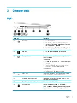
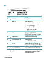
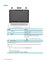
Page 24: ...16 Chapter 2 Components ...

Page 25: ...TE HP continually improves and changes product parts For complete and current information on supported parts for your computer go to http partsurfer hp com select your country or region and then follow the on screen instructions Computer major components 17 ...

Page 26: ... TB 5400 rpm 778192 005 500 GB 7200 rpm 703267 005 500 GB 5400 rpm 778186 005 10 System board includes replacement thermal materials All system boards use the following part numbers xxxxxx 001 Non Windows operating systems xxxxxx 601 Windows 10 operating system Intel Core i5 7200U processor 925422 xx1 Intel Core i3 6006U processor 925423 xx1 Intel Celeron N3060 processor 925425 xx1 11 WLAN module ...

Page 27: ...els with UMA graphics memory and Intel Core processors 925348 001 16 For use in models with UMA graphics and Intel Pentium or Celeron processors 925347 001 17 Battery 4 cell 41 Whr 2 8 Ah Li ion battery 919701 850 3 cell 31 Whr 2 8 Ah Li ion battery 919700 850 18 Optical drive DVD RW Double Layer SuperMulti 920417 001 19 Bottom cover For use in models with an optical drive 929157 001 For use in mo...

Page 28: ...umber 1 Display bezel 925335 001 2 Raw display panel 35 6 cm 14 0 in 850886 003 3 Camera microphone module HD 919471 001 VGA 919472 001 4 Hinge cover Right 931551 001 Left 931552 001 5 Hinge Kit left and right 925356 001 20 Chapter 3 Illustrated parts catalog ...

Page 29: ...torage devices Item Component Spare part number 1 Hard drive SATA does not include brackets connector board or cable 1 TB 5400 rpm 778192 005 500 GB 7200 rpm 703267 005 500 GB 5400 rpm 778186 005 2 Hard drive bracket 925354 001 3 Optical drive DVD RW Double Layer SuperMulti 920417 001 4 Optical drive bezel 929158 001 5 Optical drive bracket 925353 001 Mass storage devices 21 ...

Page 30: ...us parts Component Spare part number HP Smart AC adapter 4 5 mm non PFC 65 W EM for use in India and the People s Republic of China 913691 850 45 W 741727 001 Power cord For use in Argentina 920688 003 For use in Australia 920688 011 For use in Denmark 920688 007 For use in Europe 920688 005 For use in India 920688 016 For use in Israel 920688 008 22 Chapter 3 Illustrated parts catalog ...

Page 31: ...ple s Republic of China 920688 014 For use in South Africa 920688 010 For use in South Korea 920688 013 For use in Switzerland 920688 009 For use in Taiwan 920688 015 For use in Thailand 920688 012 For use in the United Kingdom 920688 006 Power adapter For use in Japan 226768 001 Screw Kit 925375 001 Rubber Feet Kit Miscellaneous parts 23 ...

Page 32: ...24 Chapter 3 Illustrated parts catalog ...

Page 33: ... and reassembly can damage plastic parts Use care when handling the plastic parts Apply pressure only at the points designated in the maintenance instructions Cables and connectors CAUTION When servicing the computer be sure that cables are placed in their proper locations during the reassembly process Improper cable placement can damage the computer Cables must be handled with extreme care to avo...

Page 34: ... Electronic components are sensitive to electrostatic discharge ESD Circuitry design and structure determine the degree of sensitivity Networks built into many integrated circuits provide some protection but in many cases ESD contains enough power to alter device parameters or melt silicon junctions A discharge of static electricity from a finger or other conductor can destroy static sensitive dev...

Page 35: ...ly Store reusable ESD sensitive parts from assemblies in protective packaging or non conductive foam Use transporters and conveyors made of antistatic belts and roller bushings Be sure that mechanized equipment used for moving materials is wired to ground and that proper materials are selected to avoid static charging When grounding is not possible use an ionizer to dissipate electric charges Work...

Page 36: ...operator and ground To be effective the conductive must be worn in contact with the skin The following grounding equipment is recommended to prevent electrostatic damage Antistatic tape Antistatic smocks aprons and sleeve protectors Conductive bins and other assembly or soldering aids Nonconductive foam Conductive tabletop workstations with ground cords of one megohm resistance Static dissipative ...

Page 37: ...gion and then follow the on screen instructions Component replacement procedures NOTE Please read and follow the procedures described here to access and replace Customer Self Repair parts successfully NOTE Details about your computer including model serial number product key and length of warranty are on the service tag at the bottom of your computer See Labels on page 15 for details This chapter ...

Page 38: ...evices connected to the computer 3 Disconnect the power from the computer by first unplugging the power cord from the AC outlet and then unplugging the AC adapter from the computer To remove the battery 1 Position the computer upside down on a flat surface 2 Slide the battery lock latch 1 to unlock the battery and then slide the battery release latch 2 to release the battery NOTE The battery relea...

Page 39: ...d then shut it down through the operating system 2 Disconnect all external devices connected to the computer 3 Disconnect the power from the computer by first unplugging the power cord from the AC outlet and then unplugging the AC adapter from the computer 4 Remove the battery see Battery on page 30 To remove the optical drive 1 Remove the Phillips PM2 5 6 0 screw 1 that secures the optical drive ...

Page 40: ...tate the side of the bezel 3 and the remove it 4 4 If it is necessary to replace the bracket on the rear of the optical drive remove the Phillips PM2 0 2 5 screw 1 that secures the bracket to the drive and then remove the bracket 2 Reverse this procedure to reassemble and install the optical drive 32 Chapter 5 Removal and replacement procedures for Customer Self Repair parts ...

Page 41: ...Display subcomponents bezel panel camera NOTE Display assemblies are spared at the subcomponent level only This section illustrates how to remove the display bezel display panel and camera module without removing the display from the computer The Display assembly on page 59 section illustrates removing all display subcomponents To remove the display assembly subcomponents follow these steps 1 Shut...

Page 42: ...ssembly with the top edge toward you b Pry up to disengage the camera microphone module from the adhesive that secures it to the display 1 c Disconnect the cable 2 from the module 4 To remove the display panel 34 Chapter 6 Removal and replacement procedures for Authorized Service Provider parts ...

Page 43: ...b Rotate the display panel onto the keyboard 2 to gain access to the display cable connection on the back of the panel c On the back of the display panel release the adhesive strip that secures the display panel cable to the display panel and then disconnect the cable 1 Component replacement procedures 35 ...

Page 44: ...ve the display panel from the computer 2 Reverse this procedure to reassemble and install the display assembly components 36 Chapter 6 Removal and replacement procedures for Authorized Service Provider parts ...

Page 45: ...rating system 2 Disconnect all external devices connected to the computer 3 Disconnect the power from the computer by first unplugging the power cord from the AC outlet and then unplugging the AC adapter from the computer 4 Remove the battery see Battery on page 30 5 Remove the optical drive see Optical drive on page 31 if installed To remove the bottom cover 1 Remove the 2 Phillips PM2 5 5 0 scre...

Page 46: ... plastic non marking tool 1 to pry the bottom cover from the computer 2 Reverse this procedure to install the bottom cover 38 Chapter 6 Removal and replacement procedures for Authorized Service Provider parts ...

Page 47: ...the computer If you are unsure whether the computer is off or in Hibernation turn the computer on and then shut it down through the operating system 2 Disconnect all external devices connected to the computer 3 Disconnect the power from the computer by first unplugging the power cord from the AC outlet and then unplugging the AC adapter from the computer 4 Remove the battery see Battery on page 30...

Page 48: ...ennas are not connected to the terminals on the WLAN module the protective sleeves must be installed on the antenna connectors as shown in the following illustration Reverse this procedure to install the WLAN module 40 Chapter 6 Removal and replacement procedures for Authorized Service Provider parts ...

Page 49: ...Hibernation turn the computer on and then shut it down through the operating system 2 Disconnect all external devices connected to the computer 3 Disconnect the power from the computer by first unplugging the power cord from the AC outlet and then unplugging the AC adapter from the computer 4 Remove the battery see Battery on page 30 5 Remove the optical drive see Optical drive on page 31 if insta...

Page 50: ...move the memory module 2 by pulling it away from the slot at an angle Reverse this procedure to install a memory module 42 Chapter 6 Removal and replacement procedures for Authorized Service Provider parts ...

Page 51: ...de the hard drive bracket Description Spare part number Hard drives 1 TB 5400 rpm 778192 005 500 GB 7200 rpm 703267 005 500 GB 5400 rpm 778186 005 Hard drive bracket 925354 001 Before removing the hard drive follow these steps 1 Shut down the computer If you are unsure whether the computer is off or in Hibernation turn the computer on and then shut it down through the operating system 2 Disconnect...

Page 52: ...the hard drive assembly from the computer 3 3 To remove the hard drive bracket from the hard drive remove the four Phillips PM3 0 3 0 screws 1 that secure the bracket to the hard drive 44 Chapter 6 Removal and replacement procedures for Authorized Service Provider parts ...

Page 53: ...4 Remove the hard drive bracket from the hard drive 2 Reverse this procedure to reassemble and install the hard drive Component replacement procedures 45 ...

Page 54: ... removing the fan heat sink assembly follow these steps 1 Shut down the computer If you are unsure whether the computer is off or in Hibernation turn the computer on and then shut it down through the operating system 2 Disconnect all external devices connected to the computer 3 Disconnect the power from the computer by first unplugging the power cord from the AC outlet and then unplugging the AC a...

Page 55: ...3 Remove the fan from the computer 3 Reverse this procedure to install the fan Component replacement procedures 47 ...

Page 56: ...st unplugging the power cord from the AC outlet and then unplugging the AC adapter from the computer 4 Remove the battery see Battery on page 30 5 Remove the optical drive see Optical drive on page 31 if installed 6 Remove the bottom cover see Bottom cover on page 37 To remove the TouchPad button board 1 Disconnect the cable from the TouchPad button board 1 2 Remove the two Phillips PM2 0 3 0 scre...

Page 57: ...ced through the ventilation grill located on the left side of the computer Before removing the heat sink assembly follow these steps 1 Shut down the computer If you are unsure whether the computer is off or in Hibernation turn the computer on and then shut it down through the operating system 2 Disconnect all external devices connected to the computer 3 Disconnect the power from the computer by fi...

Page 58: ...ete graphics Thermal paste is used on the processor and associated heat sink area 1 2 as well as the graphics chip and associated heat sink area 3 4 4 50 Chapter 6 Removal and replacement procedures for Authorized Service Provider parts ...

Page 59: ...Figure 6 2 UMA graphics UMA graphics Thermal paste is used on the heat sink 1 and the processor 2 5 Component replacement procedures 51 ...

Page 60: ... graphics fanless Thermal paste is used on the heat sink 1 and the processor 2 Reverse this procedure to reassemble and install the heat sink assembly 52 Chapter 6 Removal and replacement procedures for Authorized Service Provider parts ...

Page 61: ...nect the power from the computer by first unplugging the power cord from the AC outlet and then unplugging the AC adapter from the computer 4 Remove the battery see Battery on page 30 5 Remove the optical drive see Optical drive on page 31 if installed 6 Remove the bottom cover see Bottom cover on page 37 To remove the speakers 1 Disconnect the speaker cable from the system board 1 2 Remove the ca...

Page 62: ...4 Lift up and remove the speakers from the computer 4 Reverse this procedure to install the speakers 54 Chapter 6 Removal and replacement procedures for Authorized Service Provider parts ...

Page 63: ... to the computer 3 Disconnect the power from the computer by first unplugging the power cord from the AC outlet and then unplugging the AC adapter from the computer 4 Remove the battery see Battery on page 30 5 Remove the optical drive see Optical drive on page 31 if installed 6 Remove the bottom cover see Bottom cover on page 37 7 Remove the speakers see Speakers on page 53 To remove the USB boar...

Page 64: ... Disconnect all external devices connected to the computer 3 Disconnect the power from the computer by first unplugging the power cord from the AC outlet and then unplugging the AC adapter from the computer 4 Remove the battery see Battery on page 30 5 Remove the optical drive see Optical drive on page 31 if installed 6 Remove the bottom cover see Bottom cover on page 37 7 Remove the WLAN module s...

Page 65: ... 5 screws 1 that secure the system board to the computer 3 Rotate the side of the board upward 2 and then lift the system board out of the computer 3 Reverse this procedure to install the system board Component replacement procedures 57 ...

Page 66: ...the power cord from the AC outlet and then unplugging the AC adapter from the computer 4 Remove the battery see Battery on page 30 5 Remove the optical drive see Optical drive on page 31 if installed 6 Remove the bottom cover see Bottom cover on page 37 7 Remove the system board see System board on page 56 To remove the RTC battery 1 Position the system board upside down 2 Using a thin tool diseng...

Page 67: ...onnected to the computer 3 Disconnect the power from the computer by first unplugging the power cord from the AC outlet and then unplugging the AC adapter from the computer 4 Remove the battery see Battery on page 30 5 Remove the optical drive see Optical drive on page 31 if installed 6 Remove the bottom cover see Bottom cover on page 37 To remove the display assembly 1 Disconnect the display pane...

Page 68: ...ttom edge 3 of the display bezel until the bezel disengages from the display enclosure NOTE When removing the bezel from the bottom of the display 3 be careful not to peel the Mylar from the bottom of the display panel b Remove the display bezel 4 NOTE The display will not be connected to the computer as shown in the following image 60 Chapter 6 Removal and replacement procedures for Authorized Se...

Page 69: ...y up to disengage the camera microphone module from the adhesive that secures it to the display 1 c Disconnect the cable 2 from the module 3 To remove the display panel a Remove the four Phillips PM2 0 3 0 screws 1 that secure the display panel to the top of the enclosure Component replacement procedures 61 ...

Page 70: ...TE The display will not be connected to the computer as shown in the following image c On the back of the display panel release the adhesive strip that secures the display panel cable to the display panel and then disconnect the cable 1 62 Chapter 6 Removal and replacement procedures for Authorized Service Provider parts ...

Page 71: ...computer 2 NOTE The display will not be connected to the computer as shown in the following image 4 To remove the display hinges a Pull either side of each hinge cap to disengage it from the enclosure 1 Component replacement procedures 63 ...

Page 72: ...ews 1 and then lift the top display hinge 2 off the display d Remove the three broadhead Phillips PM2 5 3 0 screws 1 and the PM2 0 3 0 screw 2 that secure each hinge to the display enclosure 64 Chapter 6 Removal and replacement procedures for Authorized Service Provider parts ...

Page 73: ...play hinges 3 5 To remove the wireless antennas an cables release the cables from the clips built into the side of the display enclosure 1 and then remove the antennas and cables 2 3 Component replacement procedures 65 ...

Page 74: ...era cable remove the cable from the clips built into the side of the display enclosure 1 and then remove the cable from the display enclosure 2 66 Chapter 6 Removal and replacement procedures for Authorized Service Provider parts ...

Page 75: ...the display enclosure be sure that the subcomponents including the camera microphone module the antenna receivers and all associated cables and hardware are transferred to the new enclosure Reverse this procedure to reassemble and install the display assembly Component replacement procedures 67 ...

Page 76: ...d from the AC outlet and then unplugging the AC adapter from the computer 4 Remove the battery see Battery on page 30 5 Remove the optical drive see Optical drive on page 31 if installed 6 Remove the bottom cover see Bottom cover on page 37 7 Remove the display see Display assembly on page 59 To remove the power connector cable 1 Disconnect the power connector cable from the system board 1 2 Use a...

Page 77: ...rd from the AC outlet and then unplugging the AC adapter from the computer 4 Remove the battery see Battery on page 30 5 Remove the optical drive see Optical drive on page 31 if installed 6 Remove the bottom cover see Bottom cover on page 37 7 Remove the display see Display assembly on page 59 To remove the power button board 1 Remove the Phillips PM2 0 3 0 screw 1 that secures the power button bo...

Page 78: ... top cover keyboard The second table provides the country codes NOTE All top cover keyboard spare part kits include TouchPad Description Spare part number Jet black 929159 xx1 For use in country or region Spare part number For use in country or region Spare part number Brazil 201 South Korea AD1 India D61 Taiwan AB1 Latin America 161 Thailand 281 Japan 291 United States 001 70 Chapter 6 Removal an...

Page 79: ...e on the HP website Most BIOS updates on the HP website are packaged in compressed files called SoftPaqs Some download packages contain a file named Readme txt which contains information regarding installing and troubleshooting the file Determining the BIOS version To decide whether you need to update Setup Utility BIOS first determine the BIOS version on your computer To reveal the BIOS version i...

Page 80: ...y the most recent BIOS update and compare it to the BIOS version currently installed on your computer If the update is more recent than your BIOS version make a note of the date name or other identifier You may need this information to locate the update later after it has been downloaded to your hard drive b Follow the on screen instructions to download your selection to the hard drive Make a note...

Page 81: ...the HP Recovery partition on the computer The backup can be used to reinstall the original operating system in cases where the hard drive is corrupted or has been replaced For information on creating recovery media see Creating HP Recovery media select products only on page 73 For information on the recovery options that are available using the recovery media see Using Windows tools on page 74 Use...

Page 82: ...arately to create recovery discs If you use an external optical drive it must be connected directly to a USB port on the computer the drive cannot be connected to a USB port on an external device such as a USB hub If you cannot create DVD media yourself you can obtain recovery discs for your computer from HP See the Worldwide Telephone Numbers booklet included with the computer You can also find c...

Page 83: ...o remove the Recovery partition to reclaim hard drive space HP Recovery Manager offers the Remove Recovery Partition option For more information see Removing the HP Recovery partition select products only on page 78 Recovering using HP Recovery Manager HP Recovery Manager software allows you to recover the computer to its original factory state by using the HP Recovery media that you either create...

Page 84: ...rking To start HP Recovery Manager from the HP Recovery partition IMPORTANT For a tablet with a detachable keyboard connect the tablet to the keyboard base before beginning these steps select products only 1 Type recovery in the taskbar search box select Recovery Manager and then select HP Recovery Environment or For computers or tablets with keyboards attached press f11 while the computer boots o...

Page 85: ...ard base before beginning these steps 1 Insert the HP Recovery media 2 Access the system Startup menu For computers or tablets with keyboards attached Turn on or restart the computer or tablet quickly press esc and then press f9 for boot options For tablets without keyboards Turn on or restart the tablet and then quickly hold down the volume up button then select f9 or Turn on or restart the table...

Page 86: ...overy partition So before you remove the Recovery partition create HP Recovery media see Creating HP Recovery media select products only on page 73 NOTE The Remove Recovery Partition option is only available on products that support this function Follow these steps to remove the HP Recovery partition 1 Type recovery in the taskbar search box and then select HP Recovery Manager 2 Select Remove Reco...

Page 87: ...lowing order a Connected USB drive NOTE To download the HP PC Hardware Diagnostics UEFI tool to a USB drive see Downloading HP PC Hardware Diagnostics UEFI to a USB device on page 79 b Hard drive c BIOS 3 When the diagnostic tool opens select the type of diagnostic test you want to run and then follow the on screen instructions NOTE If you need to stop a diagnostic test press esc Downloading HP PC...

Page 88: ...ides a BIOS crisis recovery tool through the HP PC Hardware Diagnostics 3 in 1 USB key This tool can be used by HP authorized service providers to recover systems that have failed due to a corrupted BIOS For more information about using the 3 in 1 USB key for BIOS crisis recovery go to http www hp com go techcenter pcdiags Additional information is included in the web based training offered by HP ...

Page 89: ... V dc 2 31 A 45 W Temperature Operating 5 C to 35 C 41 F to 95 F Nonoperating 20 C to 60 C 4 F to 140 F Relative humidity noncondensing Operating 10 to 90 Nonoperating 5 to 95 Maximum altitude unpressurized Operating 15 m to 3 048 m 50 ft to 10 000 ft Nonoperating 15 m to 12 192 m 50 ft to 40 000 ft NOTE Applicable product safety standards specify thermal limits for plastic surfaces The device ope...

Page 90: ...ifications Metric U S Active diagonal size 35 6 cm 14 0 in Resolution 1366x768 HD Surface treatment Anti glare Brightness 220 nits Viewing angle SVA Backlight WLED Graphics adapter eDP Thickness 3 0 mm 82 Chapter 10 Specifications ...

Page 91: ...ecurity Seek times typical read including setting Single track 2 0 ms 3 ms Average read write 12 ms 13 ms Maximum 22 ms 24 ms Logical blocks 1 953 525 168 1 048 576 000 Disk rotational speed 5400 rpm 5400 rpm or 7200 rpm Operating temperature 1 GB 1 billion bytes when referring to hard drive storage capacity Actual accessible capacity is less NOTE Certain restrictions and exclusions apply Contact ...

Page 92: ...n Disc diameter Standard disc 12 cm 4 72 in Mini disc 8 cm 3 15 in Disc thickness 1 2 mm 0 047 in Track pitch 0 74 µm Access time CD DVD Random 175 ms 230 ms Full stroke 285 ms 335 ms Audio output level Line out 0 7 Vrms Cache buffer 2 MB Data transfer rate 24X CD ROM 3 600 KB sec 8X DVD ROM 10 800 KB sec 24X CD R 3 600 KB sec 16X CD RW 2 400 KB sec 8X DVD R 10 800 KB sec 4X DVD RW 5 400 KB sec 8X...

Page 93: ... keyboard base before beginning steps in this chapter Current BIOS steps 1 Follow steps a through l below to restore the nonvolatile memory that can contain personal data Restoring or reprogramming nonvolatile memory that does not store personal data is neither necessary nor recommended a Turn on or restart the computer and then press esc while the Press the ESC key for Startup Menu message is dis...

Page 94: ...or fingerprint reader one or two prompts will appear one to clear the TPM and the other to Reset Fingerprint Sensor press or tap F1 to accept or F2 to reject l Remove all power and system batteries for at least 24 hours 2 Complete one of the following Remove and retain the storage drive or Clear the drive contents by using a third party utility designed to erase data from an SSD or Clear the conte...

Page 95: ... EEPROM 64 KBytes not customer accessible No Yes Stores NIC configuration and NIC firmware NIC EEPROM is programmed using a utility from the NIC vendor that can be run from DOS A utility is required to write data to this memory and is available from the NIC vendor Writing data to this ROM in an inappropriate manner will render the NIC non functional DIMM Serial Presence Detect SPD configuration da...

Page 96: ...sing this utility Bluetooth flash select products only 2 Mbit No Yes Stores Bluetooth configuration and firmware Bluetooth flash is programmed at the factory Tools for writing data to this memory are not publicly available but can be obtained from the silicon vendor A utility is required for writing data to this memory and is made available through newer versions of the driver whenever the flash r...

Page 97: ...ic system diagnostics The UEFI BIOS provides functionality beyond that of the legacy BIOS In addition the UEFI BIOS works to initialize the computer s hardware before loading and executing the OS the run time environment allows the loading and execution of software programs from storage devices to provide more functionality such as advanced hardware diagnostics with the ability to display more det...

Page 98: ...ot Keys a Turn on or restart the computer and then press esc while the Press the ESC key for Startup Menu message is displayed at the bottom of the screen b Select the Security menu select Secure Boot Configuration and then follow the on screen instructions c At the Secure Boot Configuration window select Secure Boot select Clear Secure Boot Keys and then follow the on screen instructions to conti...

Page 99: ...ng requirements are applicable to all countries and regions The length of the power cord set must be at least 1 5 m 5 0 ft and no more than 2 0 m 6 5 ft All power cord sets must be approved by an acceptable accredited agency responsible for evaluation in the country or region where the power cord set will be used The power cord sets must have a minimum current capacity of 10 A and a nominal voltag...

Page 100: ...orea KTL 5 Sweden SEMKO 1 Switzerland SEV 1 Taiwan BSMI 6 Thailand TISI 1 The United Kingdom ASTA 1 The United States UL 2 1 The flexible cord must be Type HO5VV F 3 conductor 0 75mm2 conductor size Power cord set fittings appliance coupler and wall plug must bear the certification mark of the agency responsible for evaluation in the country or region where it will be used 2 The flexible cord must...

Page 101: ...wall plug must bear the CCC certification mark 5 The flexible cord must be Type H05VV F 3X0 75mm2 conductor size KTL logo and individual approval number must be on each element Corset approval number and logo must be printed on a flag label 6 The flexible cord must be Type HVCTF 3X1 25mm2 conductor size Power cord set fittings appliance coupler cable and wall plug must bear the BSMI certification ...

Page 102: ...94 Chapter 12 Power cord set requirements ...

Page 103: ...he battery in general household waste Follow the local laws and regulations in your area for battery disposal HP encourages customers to recycle used electronic hardware HP original print cartridges and rechargeable batteries For more information about recycling programs see the HP Web site at http www hp com recycle 95 ...

Page 104: ...96 Chapter 13 Recycling ...

Page 105: ...nents illustrated 17 computer specifications 81 connector power 6 connectors service considerations 25 D display assembly illustrated 18 removing 59 display assembly subcomponents illustrated 20 removing 59 display bezel illustrated 20 removing 33 60 display cable illustrated 21 removing 63 display enclosure illustrated 21 removing 67 display panel illustrated 20 product description 1 removing 34 ...

Page 106: ...6 minimized image creating 75 model name 1 N network jack identifying 6 nonvolatile memory 85 O operating system 3 optical drive illustrated 19 21 precautions 26 product description 2 removing 31 specifications 84 optical drive bezel illustrated 21 optical drive bracket illustrated 21 optical drive eject button identifying 5 optical drive rear bracket removing 32 optical drive identifying 5 origin...

Page 107: ...ated 18 removing 53 speakers identifying 14 specifications computer 81 display 82 DVD RW SuperMulti DL Drive 84 hard drive 83 optical drive 84 supported discs recovery 74 system board removing 56 spare part number 18 56 system memory removing personal data from volatile 85 system recovery 75 system restore point creating 74 system restore point creating 73 T tools required 25 top cover keyboard re...

Page 108: ...100 Index ...

Reviews: