background image

Document 800-07422 – Rev A – 08/10

Installation and User Guide

UltraKey Lite

Keyboard controller for VideoBloX

and MAXPRO-Net Matrix Systems

HJC5000

Summary of Contents for UltraKey Lite HJC5000

Page 1: ...Document 800 07422 Rev A 08 10 Installation and User Guide UltraKey Lite Keyboard controller for VideoBloX and MAXPRO Net Matrix Systems HJC5000 ...

Page 2: ......

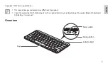
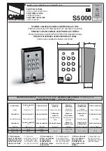
Page 3: ...Installation and User Guide ...

Page 4: ...ode corrected IP address p 59 updated images for quality 800 07422 rev A 08 2010 Revisions to Step 3 Configure Address Baud Rate or IP for VideoBloX Mode Step 4 Configure VideoBloX Mode Default Settings While Powering Up Step 4 Configure the Controller for an Ethernet Connection added Step 5 Setting the Keyboard Address While Powering Up and the System Configuration Menu screen 4 ...

Page 5: ...g antenna increasing the separation between the equipment and receiver or connecting the equipment to an outlet on a different circuit This device complies with part 15 of the FCC rules Operation is subject to the following two conditions 1 This device may not cause harmful interference and 2 this device must accept any interference received including interference that may cause undesired operatio...

Page 6: ...statutes concerning the monitoring and recording of video and audio signals Honeywell shall not be held responsible for the use of this product in violation of current laws and statutes Warnings and Cautions Read the following cautions and warnings prior to installation and use of this product Changes or modifications not expressly approved by the party responsible for compliance could void the us...

Page 7: ... company 4 HEAT Situate away from items that produce heat or are heat sources such as radiators heat registers stoves or other products including amplifiers 5 WATER AND MOISTURE Do not use this unit near water or in an unprotected outdoor installation or any area classified as a wet location 6 ATTACHMENTS Do not use attachments not recommended by the product manufacturer as they may result in the ...

Page 8: ...rvice for assistance or to request a Return Merchandise Authorization RMA number Be sure to have the model number serial number and the nature of the problem available for the technical service representative In the U S A and Canada call 1 800 796 2288 See the back cover for other contact details Prior authorization must be obtained for all returns exchanges or credits Items shipped to Honeywell w...

Page 9: ...s 24 MAXPRO Key Functions 27 3 Installing UltraKey Lite with VideoBloX 31 Navigating the LCD Configuration Menus 31 Installing and Configuring a Serial Connection 32 Installing and Configuring an Ethernet Connection 36 Optional Configuring UltraKey Lite Using the Web Browser 41 4 Installing UltraKey Lite with MAXPRO Net 47 Navigating the LCD Configuration Menus 47 Installing and Configuring a Seri...

Page 10: ...10 ...

Page 11: ...guration Tab 43 Figure 3 11 Serial Port Configuration Tab 44 Figure 3 12 IP Configuration Tab 44 Figure 3 13 DynKey Configuration Tab 45 Figure 4 1 LCD and Navigation Keys 48 Figure 4 2 MAXPRO LCD Menu Tree 48 Figure 4 3 RS232 Serial Port Connection 50 Figure 4 4 RS232 Serial Port Connection and MegaPIT 50 Figure 4 5 RS232 Serial Port Connection and MX18 51 Figure 4 6 AC Power Adapter with CEE 7 1...

Page 12: ...12 Figure 5 2 Change Password Page 69 Figure 5 3 System Configuration LCD Menu Tree All Modes 70 ...

Page 13: ...nctions 24 Table 2 3 MAXPRO Key Functions 27 Table 3 1 Serial Port COM1 and COM2 Pin Assignments 33 Table 3 2 RJ45 Ethernet Pin Assignments 37 Table 3 3 Setting the Keyboard Address 41 Table 4 1 Serial Port COM1 and COM2 Pin Assignments 49 Table 4 2 Terminal Box COM1 and COM2 Pin Assignments 52 Table 4 3 RJ45 Ethernet Pin Assignments 56 Table 4 4 Setting the Keyboard Address 60 Table 5 1 HJC5000 U...

Page 14: ...14 ...

Page 15: ...s these modes available depending on the installation MAXPRO For use with MAXPRO Net Matrix System installations VideoBloX For use with VideoBloX Matrix System installations Note This installation and user guide describes the Honeywell VideoBloX and MAXPRO Net Video Matrix mode installation and set up Future product and documentation releases will include the Standalone mode for PTZ and DVR functi...

Page 16: ...u The System Set Mode screen displays Lucida Values of editable fields that are mentioned in the body text of the document for reference purposes but do not need to be entered as part of a procedure The Time from field can be set to Hours Minute Seconds Text strings displayed on the screen Syntax The message Unauthorized displays object entered Swiss721 BT Bold Words or characters that are part of...

Page 17: ...ernet 10Base T 100Base TX RJ45 with LED 1 RS232 422 485 RJ45 with LED LCD Type STN Positive Image Backlight Blue White Characters 122 32 Dots USB Type A Version USB1 1 For USB PC Keyboard Compliance EN55022 for radiated and conducted emissions Mechanical Dimensions 408 mm L 215 mm W 105 mm H Gross Weight 3 2 kg Cover material ABS PC cool gray Environment Operating Temperature 10 to 55 deg C Storag...

Page 18: ...uroplug 2 5 A 250V unearthed NEMA 1 15 North American 15 A 125V ungrounded BS1363 British 13A 230 240V 50 Hz earthed and fused CPCS CCC Chinese 10 A 250V AS 3112 Australian 10 A 240V 1 Connector adapter RJ45 to DB9 male for RS422 Backwards compatibility with VideoBloX and VideoBloX Lite CPU installations VideoBloX master port 2 Connector adapter RJ45 to DB9 female for RS232 Backwards compatibility...

Page 19: ...cal power requirements Ethernet Port Note Ethernet is used to connect to the controller web browser MAXPRO Net or VideoBloX NetCPU 10 100M Ethernet PoE power over Ethernet input If PoE is the power input it is not recommended to connect this network with an outside building TCP IP protocol on the controller For VideoBloX the controller address range can be between 1 and 32 For MAXPRO Net the addre...

Page 20: ...ng the controller LCD menu and cannot be used at the same time Note Serial port 1 can be either RS485 or RS422 Serial port 2 is only RS232 Terminal Box Use the terminal box RJ45 port and 8 pin terminal plug as required for compatibility and connectivity options It can be used to break out the RJ45 cable when wiring to existing infrastructure is required Figure 1 2 Terminal Box Front and Back Ports...

Page 21: ...pendent on the mode selected Functions only used with the Standalone Mode for PTZ DVR functions are not described in this document and will be included in future releases Logging Onto the Controller 1 Connect the keyboard with a power adapter 12V 10 DC 1 A included or a network cable with PoE 2 To configure the main menu settings press Alt Clr 3 Enter the PIN password 3434 Note If an invalid passw...

Page 22: ...with a VideoBloX system See Table 2 3 for UltraKey Lite key functions when used with a MAXPRO Net system Figure 2 1 UltraKey Lite Controller Keyboard Layout See Figure 2 2 for a brief overview of the three main navigation options See Table 2 1 for specific methods to navigate the LCD during installation and set up 3 2 1 6 5 4 9 8 7 0 Clr Ent View Tour PTZ call Alt Review Search Alarm Seq Set Iris ...

Page 23: ...enu You can use any of these ways to access the LCD KEYS Press Ent TOUCH PAD RING Press the right arrow key JOYSTICK Move right LCD KEYS Special case to enter the Set Up menu press the LCD center key not labeled To cancel an operation or return to the previous level of the menu You can use any of these ways to access the LCD KEYS Press Alt Clr TOUCH PAD Rotate your finger in a counter clockwise mo...

Page 24: ...s the right left arrows JOYSTICK Move right left To scroll through the secondary level menu options You can use any of these ways to access the LCD LCD KEYS Press the up down arrow keys TOUCH PAD Rotate your finger clockwise or counter clockwise TOUCH PAD RING Press the forward backward arrows JOYSTICK Move up down To correct errors KEYS Press Clr Table 2 2 VideoBloX Key Functions ID Key Descripti...

Page 25: ...N 20 Camera Selects Camera mode CAM CAM 22 PTZ Call Selects Alternate camera NetCPU Enter 23 Touch wheel right Selects next camera Next Next 23 Touch wheel left Selects previous camera Prev Prev 23 Touch ring Up Nudges PTZ Up Up Up 23 Touch ring Down Nudges PTZ Down Down Down 23 Touch ring Left Nudges PTZ Left Left Left 23 Touch ring Right Nudges PTZ Right Right Right 25 Joystick Left Move PTZ lef...

Page 26: ... Define in CFG software Cash Slots Cash Slots 21 30 ALT F2 F12 Define in CFG software Cash Cage Cash Cage 21 30 ALT F3 F13 Define in CFG software Group 13 Group 13 21 30 ALT F4 F14 Define in CFG software Group 14 Group 14 21 30 ALT F5 F15 Define in CFG software Group 15 Group 15 21 30 ALT F6 F16 Define in CFG software Group 16 Group 16 21 4 ALT 4 Toggle Auxillary 4 Aux 4 Memory 21 5 ALT 5 Toggle A...

Page 27: ...ind 8 Review 85 Text Review 9 Record 79 Rec Rec 10 Search 77 Stop Stop 11 Pause Play Fwd 78 Play Play 12 Tour 102 PTZ Aux Flashback 13 View 74 View View 14 VCR 60 VCR None Menu 15 MUX Screen 50 Mux Alternate 16 1 Number 1 62 Keypad key 1 Keypad key 1 16 2 Number 2 63 Keypad key 2 Keypad key 2 16 3 Number 3 64 Keypad key 3 Keypad key 3 16 4 Number 4 66 Keypad key 4 Keypad key 4 16 5 Number 5 67 Key...

Page 28: ...t Arrow 25 Joystick Left 25 Joystick Right 25 Joystick Up 25 Joystick Down 25 Twist Zoom right 25 Twist Zoom left 27 Mon B 58 F10 Monitor B 28 Mon A 57 F9 Monitor A 29 Login 41 Active None 30 F1 30 Max Menu Group 12 30 F2 65 Up Arrow Up Arrow 30 F3 1 Full Alarm 30 F4 2 2x2 None 30 F5 34 None None 30 F6 6 Left Arrow None 30 F7 69 Down Arrow Down Arrow 30 F8 7 Right Arrow Group 1 30 F9 35 None None ...

Page 29: ...use Group 6 21 30 F10 F6 53 None Print Select 21 30 F10 F7 101 Scroll Down Scroll Down 21 30 F10 F8 54 F6 Freeze 21 30 F10 F9 28 Scan Halt Group 10 24 26 Focus 89 Focus Near Focus 24 26 Focus 88 Focus Far Focus Table 2 3 MAXPRO Key Functions cont d ID Key Description Key Code Default MAX Function UltraKey ...

Page 30: ...30 Using the UltraKey Lite Controller ...

Page 31: ...uides for more information This section explains how to connect the UltraKey Lite controller to VideoBloX and how to enter the basic configuration settings specific to VideoBloX UltraKey Lite can control the remote VideoBloX via either the serial port or the Ethernet Navigating the LCD Configuration Menus Note The use of the arrow keys under the LCD is used for the following instructions See Figur...

Page 32: ...tion Step 1 Connect to the UltraKey Lite Using the Serial Port Note Use only COM1 when in VideoBloX mode See Table 3 1 below Right arrow key Left arrow key Up arrow key Down arrow key Numeric keypad and Ent key Mode Selection VideoBloX Connection Configuration Serial Port Ethernet Set Up IP Address Address 1 to 32 Baud Rate Control Mode 159 099 251 230 Ethernet Serial Port ...

Page 33: ... source 3 Connect an RJ45 network cable to the controller serial port 4 Connect the RJ45 network cable to VideoBloX For backwards compatibility with VideoBloX and VideoBloX Lite CPUs an RJ45 to DB9 male adapter is required and included with your shipment See Figure 3 4 For VideoBloX NetCPU the installation is a direct connection with the RJ45 network cable also included See Figure 3 5 and Figure 3...

Page 34: ...o Step 3 Configure Address Baud Rate or IP for VideoBloX Mode page 35 VideoBloX RJ45 to DB9 male adapter Serial Port RJ45 network cable Controller VideoBloX Serial Port RJ45 network cable Controller VideoBloX Serial Port RS422 VIdeoBlox Master Connections RJ45 to DB9 Male VB master 1 RS422_TX 2 RS422_TX 3 RS422_RX 4 RS422_RX 5 GND RJ45 to DB9 Male RJ45 Network Cable 1 RJ45 define 1 RS485_2 RS422_2...

Page 35: ...menu then press Ent 6 Press the LCD right arrow key to scroll to enter the VB Settings menu 7 Press the right arrow key to scroll through the Set Up menu to the Control Mode submenu The current setting is displayed Serial Port or Ethernet 8 Press the up down arrow keys to scroll to Serial Port then press Ent 9 Press the LCD right arrow key to scroll to Set Up Address 10 Use the LCD up down arrow k...

Page 36: ... Time Left 3 menu displays press Alt Camera to set the VideoBlox mode 2 Set the corresponding serial port as Baud Rate 19 2 KB Data Bit 8 Parity None Stop Bit 1 Installing and Configuring an Ethernet Connection For a list of accessories see Shipping Checklist on page 18 and for port connections and pin assignments see UltraKey Lite Port Connections and Descriptions on page 19 The UltraKey Lite Con...

Page 37: ...ct VideoBloX to the network Refer to the applicable VideoBloX Installation Guide for instructions Figure 3 7 Ethernet Port Connections to VideoBloX Step 2 Configure the Controller for VideoBloX Mode Note The controller factory defaults are VideoBloX mode Address 1 baud rate 19200 bps If any other mode has been selected then see Step 2 Configure the Controller for VideoBloX Mode on page 34 to selec...

Page 38: ...nu displays 10 Press Ent Note In this field you are setting the VideoBloX NetCPU IP address To set the UltraKey Lite IP address or enter the main configuration menus press Alt Clr 11 Use the numeric keypad to enter an IP address as required then press Ent 12 Press the LCD right arrow key to scroll to Set Up Address 13 Use the LCD up down arrow keys to scroll to an address between 1 and 32 to assig...

Page 39: ...ion in an Internet Protocol network It is used to configure the network automatically Automatically configuring the network using the DHCP menu 1 Press the LCD down arrow to scroll to the Network DHCP menu 2 Press Ent and the keyboard s network will be configured automatically If the network configuration is successfull then a Succeeded message displays If the network configuration was not success...

Page 40: ...keys to scroll through the menu options and select Gateway Press Ent a Using the number keys enter a Gateway as required then press Ent to save The LCD menu displays the message GW Changed b Press the up down arrow keys to select Yes to save or No to cancel then press Ent 5 Press the LCD up down arrow keys to scroll through the menu options and select NetMask Press Ent a Using the number keys ente...

Page 41: ...dy done navigate to or copy and paste the applicable IP address into your web browser LAN connections for example http 192 168 1 9 Crossover cable connections for example http 192 168 1 9 default 2 In the User Name field enter Administrator case sensitive 3 In the Password field enter 1234 default 4 Click Login Table 3 3 Setting the Keyboard Address Key Address Key Address Alt 1 1 Alt F1 11 Alt 2 ...

Page 42: ...down list select VideoBlox 5 From the System Language drop down list select English or French 6 From the Background Light drop down list select ON or OFF 7 Click Apply to save the configuration Cancel to exit without saving or Default to restore all factory default values Figure 3 9 System Configuration Tab Step 2 Configure VideoBloX Network Settings 1 From the side menu click VideoBloX Configurat...

Page 43: ...default values 5 Go to either Step 3A or 3B to configure the system for Serial or Ethernet connections respectively Figure 3 10 VideoBloX Configuration Tab Checking the Network Connection Using the Ping Function After the IP address is entered and applied press the Ping button A green Ping button indicates the device at this IP address has replied to the ping A red Ping button indicates the device...

Page 44: ...ve the configuration Cancel to exit without saving or Default to restore all factory default values Figure 3 11 Serial Port Configuration Tab Step 3B Configure the Controller for an Ethernet Connection 1 From the side menu click IP Configuration See Figure 3 12 2 In each of the fields enter IP address subnet mask gateway and DNS values 3 Click Apply to save the configuration Cancel to exit without...

Page 45: ...Key Configuration Tab 2 In the drop down menu select the key you want to configure 3 In the right column select the function you want to add to the hard key then click Add That selected function appears in the center column 4 Repeat step 3 to add another function to the selected hard key 5 Click Apply to save Note No more than 10 functions can be configured to a hard key Note Neither the number ke...

Page 46: ...46 Installing UltraKey Lite with VideoBloX ...

Page 47: ...er guides for more information This section explains how to connect the UltraKey Lite controller to MAXPRO Net and how to enter the basic configuration settings specific to MAXPRO Net For other user configurations see the index or table of contents Navigating the LCD Configuration Menus Note The use of the arrow keys under the LCD is used for the following instructions See Figure 4 1 Also see Usin...

Page 48: ...ctions Server IP Ethernet connections only Server Port Ethernet connections only Serial port mode Serial connections only Right arrow key Left arrow key Up arrow key Down arrow key Numeric keypad and Ent key Mode Selection MAXPRO _59 099 251 132 Maxpro offline keyboard 1 Maxpro Key Code Configuration Connection RS232 directly RS422 indirectly Maxpro Setting Fixed Camera Camera 1 By Serial Port By ...

Page 49: ...ng Checklist on page 18 and for port connections see UltraKey Lite Port Connections and Descriptions on page 19 Note COM1 RS422 and COM2 RS485 are configured using the controller LCD menu and cannot be used at the same time See Table 4 1 below Table 4 1 Serial Port COM1 and COM2 Pin Assignments Serial Port Type Pin Signal COM1 RS422 1 RX 2 RX 5 GND 7 TX 8 TX RS485 7 T R 8 T R COM2 RS232 4 RXD 5 GN...

Page 50: ...2_1_TX 8 RS485_1 RS422_1_TX RS485_2 RS422_2_TX and RS232 use same UART_AC Controller 1 Controller 16 4 4 4 RJ45 Network Cable 1 RJ45 Network Cable 1 PSU 3 PSU 3 Controller 1 Controller 8 RS232 MEGAPIT 1 Controller 249 RS232 Controller 256 MEGAPIT 32 MEGAPIT 1 RS422_TX 2 RS422_TX 3 NC 4 RS232TX 5 RS232GND 6 RS232RX 7 RS422_RX 8 RS422_RX RJ45 define 1 RS485_2 RS422_2_TX RS422_1_RX 2 RS485_2 RS422_2_...

Page 51: ...e RJ45 network cable to MAXPRO Net For RS232 backwards compatibility with MAXPRO Net CPUs plug the RJ45 to DB9 female adapter included with your shipment into the applicable port of MAXPRO Net See Figure 4 7 Figure 4 7 RJ45 to DB9 Female Adapter RS232 Controller 1 Controller 8 MX18 RJ11 Flat Ribbon Cable straight RJ11 Flat Ribbon Cable straight RJ45 define 1 RS485_2 RS422_2_TX RS422_1_RX 2 RS485_2...

Page 52: ...l box to an RS422 to RS232 converter supplied by the installer or customer 4 Connect the RS422 to RS232 converter to the MAXPRO Net RS232 port See Figure 4 8 Figure 4 8 RS422 to RS232 Converter Using the Terminal Box RS422 MAXPRO Net RS422 to RS232 converter Serial Port RS422 Terminal Box RJ45 network cable RS232 Ethernet Port RS422 COM1 Controller Table 4 2 Terminal Box COM1 and COM2 Pin Assignme...

Page 53: ...X 7 RS232GND 8 RS232GND RS485_2 RS422_2_TX and RS232 use same UART_AC PL2 RJ45 PL1 Terminal Box DB9 male Controller 1 Controller 16 2 2 MAXPRO Serial Port RS232 and Terminal Box RS422 RJ45 Network Cable 1 RJ45 Network Cable 1 PSU 3 PSU 3 Controller 1 Controller 8 MX18 PL2 RJ45 PL1 Terminal Box DB9 male PL2 RJ45 PL1 Terminal Box DB9 male PL1 1 RS485_1 RS422_1_TX 2 RS485_1 RS422_1_TX 3 RS485_2 RS422...

Page 54: ...two screens display If the controller is able to connect to the MAXPRO network the LCD displays the connection for example fixed camera 1 has sent a signal from MAXPRO to the controller If the controller is not able to connect to the MAXPRO network the offline menu displays If this menu displays you cannot configure the serial or ethernet connections in the next step Step 3 Configure Address Baud ...

Page 55: ... keys to select Normal or High Press Ent to save 9 Press the down LCD arrow key to scroll to Serial Port Mode Press Ent and use the up down arrow keys to select RS232 or RS422 Press Ent to save Note In the following fields you are setting the MAXPRO Net Server IP address and port number To set the UltraKey Lite IP address or enter the main configuration menus press Alt Clr 10 Press the down LCD ar...

Page 56: ...troller Ethernet port Up to 99 controllers can be connected to the network See Figure 4 11 2 Connect MAXPRO Net to the network Refer to the applicable MAXPRO Net Installation Guide for instructions Figure 4 11 Ethernet Port Connections to MAXPRO Net Table 4 3 RJ45 Ethernet Pin Assignments Port Pin Signal RJ45 Ethernet 1 TX 2 TX 3 RX 6 RX Ethernet Port RJ45 Network cables Ethernet Port Controller 1...

Page 57: ... menu opens 3 Press Ent 4 Use the LCD up down arrow keys to scroll to an address between 1 and 99 to assign to the controller 5 Press Ent to save 6 Press the down LCD arrow key to scroll to Joystick Speed Press Ent and use the up down arrow keys to select Normal or High Press Ent to save Note In the following fields you are setting the MAXPRO Net Server IP address and port number To set the UltraK...

Page 58: ...et Infor Menu displays the Network information including IP Address DNS Gateway and Netmask Automatically Configuring the Network Using DHCP The Dynamic Host Configuration Protocol DHCP is a computer networking protocol used by devices DHCP clients to obtain configuration information for operation in an Internet Protocol network It is used to configure the network automatically Automatically confi...

Page 59: ...raKey Lite IP address To set the VideoBloX IP address for communication purposes see Step 3 Set and Configure for an Ethernet Connection 4 Press the LCD up down arrow keys to scroll through the menu options and select Gateway Press Ent a Using the number keys enter a Gateway as required then press Ent to save The LCD menu displays the message GW Changed b Press the up down arrow keys to select Yes...

Page 60: ... copy and paste the applicable IP address into your web browser LAN connections for example http 192 168 1 9 Crossover cable connections for example http 192 168 1 9 default 2 In the User Name field enter Administrator case sensitive 3 In the Password field enter 1234 default 4 Click Login Table 4 4 Setting the Keyboard Address Key Address Key Address Alt 1 1 Alt F1 11 Alt 2 2 Alt F2 12 Alt 3 3 Al...

Page 61: ...From the System Mode drop down list select MAXPRO 5 From the System Language drop down list select English or French 6 From the Background Light drop down list select ON or OFF 7 Click Apply to save the configuration Cancel to exit without saving or Default to restore all factory default values Figure 4 13 System Configuration Tab Step 2 Configure MAXPRO Network Settings 1 From the side menu click...

Page 62: ...tion Using the Ping Function After the IP address is entered and applied press the Ping button A green Ping button indicates the device at this IP address has replied to the ping A red Ping button indicates the device at the IP address did not reply Please check that the IP address is correct and that there is a valid network path between the two IP addresses Step 3A Configure the Controller for a...

Page 63: ...Configure the Controller for an Ethernet Connection 1 From the side menu click IP Configuration 2 In each of the fields enter IP address subnet mask gateway and DNS values 3 Click Apply to save the configuration Cancel to exit without saving or Default to restore all factory default values Figure 4 16 IP Configuration Tab Step 4 Configuring the Dynamic Keys You can configure the hard keys on the w...

Page 64: ...n the right column select the function you want to add to the hard key then click Add That selected function appears in the center column 4 Repeat step 3 to add another function to the selected key 5 Click Apply to save Note No more than 10 functions can be configured to a hard key Note Neither the number key nor the Logon key can be configured ...

Page 65: ...onfig Menu 1 If not already done install and connect the controller to a power source The UltraKey Lite LCD displays 2 From the home screen press Alt Clr to enter the Password menu 3 Enter the PIN password 3434 then click Enter or Login The System Set Mode screen displays Setting the Screen Language 1 Log into the controller 2 From the System Set Config menu press the LCD up down arrow keys to scr...

Page 66: ...page 68 will download the slider firmware file but will not apply the update Use the following procedure to update the slider firmware after downloading the firmware file 1 Log into the controller 2 From the System Set Config menu press the LCD up down arrow keys to scroll to Slider Update Press Ent 3 The message Update Confirm displays 4 Press the LCD up arrow key to select Yes or No Select Yes a...

Page 67: ...ch pad specific values are displayed on the LCD 4 Press Alt Clr to exit from these test menus Restoring Defaults 1 Log onto the controller 2 Use the LCD up down arrow keys to scroll to Restore Default in the System Set Config menu then press Ent A confirmation message Restore Defaults appears in the display 3 Press the LCD up arrow key to select Yes or No Select Yes then press Ent to restore the d...

Page 68: ...top menu click the Upgrade tab The warning message Please make sure the network connection is connected during system upgrading displays See Figure 5 1 3 Click OK The Software Upgrade menu opens 4 Select a Folder from the drop down list Application FPGA Kernel or Slider Firmware 5 In the Select File field click Browse Navigate to the file and click OK 6 Click Send to start the upgrade process The ...

Page 69: ...he web browser 2 From the top menu click the System Reboot tab The Reboot System window opens 3 Click Reboot to continue or click another tab or Logout to exit without rebooting Changing the UltraKey Lite Web Browser Password 1 Log into the web browser 2 In the upper right corner click Change Password See Figure 5 2 3 In the Old Password field enter the current password 4 In the New Password field...

Page 70: ...on Adjust Bg Light Up Down Slide English French Network Language Back Light Show Net Infor Manual Setting DHCP Hardware Test Joystick Slider Serial Port VB Settings Slider Update Restore Defaults Maxpro Settings Serial Port Mode Key About IP Address Control Mode Baud Rate Address Keyboard ID Server Port Server IP Joystick Speed Baud Rate ...

Page 71: ......

Page 72: ...299 410 200 Honeywell Systems Group Deutschland Johannes Mauthe Straße 14 D 72458 Albstadt Germany www honeywell com security de 49 74 31 8 01 0 Honeywell Systems Group France Immeuble Lavoisier Parc de Haute Technologie 3 7 rue Georges Besse 92160 Antony France www honeywell com security fr 33 0 1 40 96 20 50 Honeywell Systems Group Italia SpA Via della Resistenza 53 59 20090 Buccinasco Milan Ita...

Reviews: