
USER MANUAL
32-00015-05
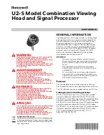
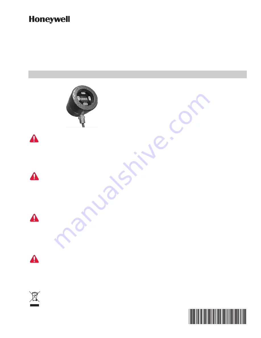
U2-S Model Combination Viewing
Head and Signal Processor
WARNING
WARNING
WARNING
Read the instructions before use. This control shall be
installed in accordance with the rules in force.
Additional versions of this manual are available online
at https://customer.honeywell.com/en-
US/Pages/default.aspx in Canadian French,
Portuguese, and German. Please enter 32-00015 in the
search box and choose Technical Literature from the
drop-down box.
AVERTISSEMENT
AVERTISSEMENT
Lire les instructions avant l'utilisation. Cette
commande doit être installée conformément aux lois
en vigueur. Des versions supplémentaires de ce manuel
sont disponibles enligne à
https://customer.honeywell.com/en-
US/Pages/default.aspx en français du Canada, en
portugais et en allemand. Veuillez inscrire 32-00015
dans le casier de recherche et choisissez
Documentation technique à partir du menu déroulant.
WARNUNG
Lesen Sie vor der Verwendung die Anweisung. Diese
Konsole muss entsprechend den geltenden
Vorschriften installiert werden. Zusätzliche Versionen
dieses Handbuchs sind online unter
https://customer.honeywell.com/en-
US/Pages/default.aspx in Frankokanadisch,
Portugiesisch und Deutsch verfügbar. Bitte geben Sie
im Suchfeld 32-00015 ein und wählen Sie Fachliteratur
im Drop-Down Menü aus
ATENÇÃO
Leia as instruções antes de usar. Esse controle tem que
ser instalado de acordo com as normas vigentes.
Outras versões desse manual estão disponíveis online
em https://customer.honeywell.com/en-
US/Pages/default.aspx em francês do Canadá,
português e alemão. Insira 32-00015 em cada caixa e
selecione Literatura Técnica na caixa suspensa.
Disposal and Recycling
Waste electrical products should not be disposed
of with general waste. Please recycle where these
facilities exist. Check with your local authority for
recycling advice.
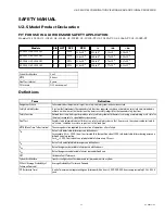
GENERAL INFORMATION
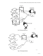
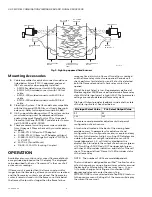
The Honeywell U2-101xS series model is a viewing head
and signal processor in a single enclosure intended for
use with a burner control system in Industrial Flame
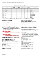
Monitoring applications. There are several options
available (see Table 1 on page 2). Each model includes
one, two, or all three sensors, and can be ordered with
quick disconnect (non-PF Models DIV2,ZN2) or pigtail
external connection method (PF Models DIV1,ZN1).
Each sensor operates independently from another,
allowing adjustment of each sensor.
IMPORTANT
Flame monitoring systems are safety systems.
Please read this manual carefully and completely
before installation and before attempting adjust-
ments.
Only qualified personnel familiar with Flame
Safety System should carry out installation and
configuration.
U2 is certified to be used in prescribed manner.
Any modification or inappropriate installation or
operation may result in unsafe operation and will
void implied or expressed warranty.
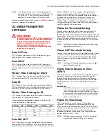
Sensors
The UV tube detector has a peak response at 210 nm.
The IR solid state sensor has a peak response at 1400 nm.
The UV solid state sensor has a peak response at 310 nm.
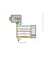
Cabling Options (Sold Separately)
ASYU2S - Quick Disconnect (non-PF) models molded
connector cable assembly with 50 foot of C22S cable.
ASYU2S-100 - Quick Disconnect (non-PF) models molded
connector cable assembly with 100 foot of C22S cable.
ASYU2S-200 - Quick Disconnect (non-PF) models molded
connector cable assembly with 200 foot of C22S cable.
ASYU2S-300 - Quick Disconnect (non-PF) models molded
connector cable assembly with 300 foot of C22S cable.
C22S - Raw shielded 12 conductor, 22g, ITC, CIC
approved. Order by the foot.


