background image

PRODUCT DATA

68- 0246

® U.S. Registered Trademark
Copyright © 2001 Honeywell •  All Rights Reserved 

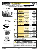
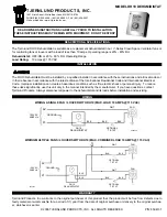
Automatic Opposed Blade Dampers

(AOBD)

APPLICATION

The opposed blade dampers are rectangular dampers with a 
24-volt, two-position, power open and closed damper motor 
used to control the volume of circulating air in heating, cooling, 
and ventilating system.

FEATURES

Anodized extruded aluminum.

Three models available:

AOBD with side-mounted motor.

AOBD-BM with bottom-mounted motor.

IOBD with internally-mounted motor.

Fully assembled and ready for installation.

For odd-size dampers, contact Honeywell Customer 
Service or your local Honeywell Sales Representative 
for pricing.

Order dampers by size and model:

Order AOBD and IOBD using width by height. 
(AOBD motor and end plate are mounted on the 
height dimension.)

Order AOBD-BM using height by width. (AOBD-BM 
motor is mounted on the width dimension.)

AOBD-BM is available only up to 20 in. wide with-
out a filler strip.

When ordering AOBD-BM dampers up to 24 in. wide, a 
filler strip up to 4 in. is built-in.

For odd-size dampers, order a one-inch filler strip for 
each odd dimension.

AOBD

AOBD-BM

IOBD

Summary of Contents for TROL-A-TEMP AOBD Series

Page 1: ...motor IOBD with internally mounted motor Fully assembled and ready for installation For odd size dampers contact Honeywell Customer Service or your local Honeywell Sales Representative for pricing Order dampers by size and model Order AOBD and IOBD using width by height AOBD motor and end plate are mounted on the height dimension Order AOBD BM using height by width AOBD BM motor is mounted on the ...

Page 2: ...ted motor AOBD BM has a bottom mounted motor IOBD has an internally mounted motor Available Sizes NOTE For odd size dampers order a one inch filler strip for each odd dimension AOBD and IOBD Sized using width by height AOBD motor and end plate are mounted on the height dimension Even sizes are available for AOBD and IOBD from 6 x 4 in to 30 x 14 in AOBD BM Sized using height by width AOBD BM motor...

Page 3: ...ES NOT AVAILABLE HEIGHT X WIDTH 10X8 12X8 12X10 14X8 14X10 AND 14X12 LISTED DAMPER WIDTH ACTUAL AIR DUCT WIDTH 1 2 2 1 1 M14850 WIDTH HEIGHT LISTED DAMPER HEIGHT 2 1 8 54 7 8 22 1 25 2 1 4 60 2 1 4 57 MOUNTING TAB 3 1 4 83 2 1 16 52 HEIGHT DIMENSIONS 4 6 8 10 12 OR 14 IN 102 152 203 254 305 OR 356 MM TO ENSURE PROPER FIT DAMPER HEIGHT IS 3 16 IN 5 MM LESS THAN THE LISTED HEIGHT DIMENSION WIDTH DIM...

Page 4: ...Installing shorter dampers Selecting Location with Humidifier Installed Recommended humidifiers are the evaporative type IMPORTANT Excessive lime or mineral deposits can accumulate on damper blades and cause improper operation when spray or atomizing type humidifiers are installed in the furnace plenum or air supply duct with the zone dampers Non recommended humidifiers are the spray or atomizer t...

Page 5: ...r small air duct sizes 20 x 8 in 18 x 10 in 16 x 12 in and smaller secure the AOBD mounting plate to the air duct with sheet metal screws provided 6 For large air duct sizes 20 x 8 in 18 x 10 in and 16 x 12 in and larger secure the mounting plate to the air duct with the sheet metal screws provided Then secure the back of the AOBD to the air duct If the back of the AOBD cannot be reached install t...

Page 6: ...DE DAMPERS IOBD SEE FIG 10 IMPORTANT Secure the IOBD by inserting the mounting screws through the front and back mounting tabs 1 Be sure the IOBD is correctly sized to the air duct 2 Select an IOBD location that is at least three feet from the furnace plenum or near an air register 3 Slide the IOBD into the air duct Be sure the electric actuator is mounted toward the top of the air duct 4 Secure t...

Page 7: ...AUTOMATIC OPPOSED BLADE DAMPERS AOBD 7 68 0246 Fig 10 Installing IOBD USE 1 4 IN 6 MM SHEET METAL SCREWS PROVIDED THROUGH MOUNTING TABS M515A ...

Page 8: ...uch as occurs when two registers diffusers or dampers supply the same room or zone the second unit is controlled by the switch action of the first unit see Fig 12 A tandem wiring diagram for use with an electric panel is shown shown in Fig 13 6 J J COOL HEAT HEAT COOL W1 Y1 ADJUST ABLE HEAT ANTICIPATOR T87F Q539B INTERNAL SCHEMATIC R1 TEMPERATURE FALL T87F 4 5 4 5 6 Z 1 2 3 X DAMPER ACTUATOR L2 L1...

Page 9: ...mper ARD 4 5 6 Z 1 2 3 X 4 5 6 Z DAMPER ACTUATORS 1 2 3 X THERMOSTAT M885 6 5 4 TO 24V T8 T7 T6 T5 T4 M6 M4 M1 4 5 6 Z 1 2 3 X DAMPER ACTUATOR 4 5 6 Z 1 2 3 X DAMPER ACTUATOR TYPICAL CONTROL PANEL 1 1 1 JUMPER TERMINALS 2 AND 5 ON DAMPER ACTUATORS M2280D T6 T5 T4 M6 M4 M1 TYPICAL CONTROL PANEL 1 2 1 2 4 5 6 Z 1 2 3 X OPPOSED BLADE DAMPER ACTUATOR TO ATTACH ARD TO OLDER STYLE 5 WIRE PANELS CONNECT ...

Page 10: ...g system operation IMPORTANT To ensure accurate temperature control do not touch or breathe on the thermostat bimetal or ther mometer Determining Damper Position See Fig 15 1 Observe that damper is open when the crank arm points toward the damper 2 Observe that damper is closed when the crank arm points away from the damper Fig 15 Determining damper position THE DAMPER IS OPEN WHEN THE CRANK ARM P...

Page 11: ... operates correctly a Remove wires from terminals 4 and 6 b Short terminals 4 and 5 to open the damper blades c Short terminals 5 and 6 to close the damper blades 1 If the dampers open and close as indicated the system is operational 2 If the dampers do not operate as indicated replace the electric actuator and repeat steps 1 and 2 4 Ensure the end switch operates correctly a Connect a 24 Vac test...

Page 12: ...d Building Control Honeywell Honeywell Limited Honeywell Limitée 1985 Douglas Drive North 35 Dynamic Drive Golden Valley MN 55422 Scarborough Ontario M1V 4Z9 Printed in U S A on recycled paper containing at least 10 post consumer paper fibers AUTOMATIC OPPOSED BLADE DAMPERS AOBD ...

Reviews: