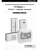
background image

TABLE OF CONTENTS

 Page 


Modular terminal


Installation Manual 


Summary of Contents for TemaKey

Page 1: ...TABLE OF CONTENTS Page 3 Modular terminal Installation Manual ...

Page 2: ...ined Assembly Single and Triple Modules 15 Fastening the Cables 17 Vertical Assembly 18 Channeling the Cables from the Bottom of the Box 19 INSTALLATION 20 Combining the Modules 20 Reader 20 Keyboards 20 Display 20 Terminals 21 Terminals with Keyboards 21 Interactive Terminals 22 Interactive Terminals with Keyboards 22 Attaching the Modules to the Wall 23 Applying the Entry Exit Labels 24 Identifi...

Page 3: ...Installation Manual Page 5 RTU T01 Numeric Keyboard Module 31 Optional Parts 32 ...

Page 4: ...ion which can be determined by tuning the equipment off and on the user is encouraged to try to correct the interference by one or more the following measures Reorient or relocate the receiving antenna Increase the separation between the equipment and receiver Connect the equipment into an outlet on a circuit different from that to which the receiver is connected Consult the dealer or an experienc...

Page 5: ...ELIMINARY OPERATIONS Mounting Instructions The cables are attached to an encased box Make sure that you place the box at a height of 120cm from the floor see Figure 1 tube cables 120 cm floor Figure 1 Space requirements for mounting ...

Page 6: ... that must be connected in parallel from one node to the next It is possible to link nodes in free topology i e by means of a star or bus configuration Cabling Recommendations Figure 2 provides an example of a typical free topology installation T e m a S e r v e r T e m a P o w e r Figure 2 Example of a free topology installation ...

Page 7: ...e Tubes and Junction Boxes Page 9 If you want to mount the tubes on the surface of the walls it is advisable to place the junction boxes under each terminal see example in Figure 3 Figure 3 Location of the junction boxes ...

Page 8: ... correct size for power cables refer to the table below Type of cable Lengt h m in relat ion t o effect ive load AWG mm2 ohm Km 100 mA 200 mA 500 mA 1 A 2 A 5 A 12 3 3 5 7 1754 877 351 175 88 35 14 2 8 8 1136 568 227 114 57 23 16 1 3 14 714 357 143 71 36 14 18 0 9 21 476 238 95 48 24 10 20 0 6 34 294 147 59 29 15 6 22 0 35 52 192 96 38 19 10 4 24 0 2 85 118 59 24 12 6 2 ...

Page 9: ...bus configuration place two terminators with resistance values of 100ohm 1 W at each end of the bus Check that the length of the LONWORKS data cable corresponds to the norms indicated in Table 1 Type of cable Length m in relation to cable capacity AWG mm2 Ohm Km 50nF Km 100nF K m 200nF K m 500nF K m 1uF Km 12 3 3 5 7 2676 1892 1338 846 598 14 2 8 8 2153 1523 1077 681 482 16 1 3 14 1707 1207 854 54...

Page 10: ...nd model AWG Connection to bus maximum total length m Connection in free topology maximum node node length max m Belden 85102 16 2700 500 Belden 8471 16 2700 400 Level IV twisted pair typically solid and unshielded 22 1400 400 JY St 2x2x0 8 4 wire helical twist solid shielded 20 900 320 Table 2 Recommended LONWORKS cables ...

Page 11: ... 2 Insert the cables in the cable clamp without pulling out the screws 3 Use the dowels to fasten the frame to the wall Make sure that the lamellar connector is in the UP position 4 Adjust the length of the cables so that they protrude by 10cm from the wall and fasten them to the cable crimp 5 Fasten the cable crimp to the contacts in the direction shown in Figure 4 6 Place the remainder of the ca...

Page 12: ...the cable clamp without pulling out the screws 3 Use the dowels to fasten the frame to the wall Make sure that the lamellar connector is in the UP position 4 Adjust the length of the cables so that they protrude by 10cm from the wall and fasten them to the cable crimp 5 Fasten the cable crimp to the contacts in the direction shown in Figure 5 6 Place the remainder of the cable inside the frame and...

Page 13: ...attachment clips at the rear of the frames see Figure 6 and Figure 7 4 Use the dowels to fasten the frame to the wall Make sure that the lamellar connector is in the UP position 5 Adjust the length of the cables so that they protrude by 10cm from the wall and fasten them to the cable crimp 6 Intertwine the terminators of the cables from the wall and the extension cable terminators and fasten them ...

Page 14: ...Page 16 Mounting the Unit on the Wall NET1 NET2 GND 12V NET1 NET2 GND 12V At t achment clip At t achment clip Figure 7 Combined assembly of single and triple module wall units ...

Page 15: ...e 17 Fastening the Cables Fasten the cable clamps to the cable bar so that the cables are arranged towards the inside of the frame see Figure 8 CONNECTIONS Å NET1 green Å NET2 yellow Å GND black Å 12V red Figure 8 Fastening the cables ...

Page 16: ...hout pulling out the screws 3 Use the dowels to fasten the frame to the wall Make sure that the lamellar connector is in the UP position 4 Adjust the length of the cables so that they protrude by 10cm from the wall and fasten them to the cable crimp 5 Fasten the cable crimp to the contacts in the direction shown in Figure 9 6 Place the remainder of the cable inside the frame and lock the cable cla...

Page 17: ... lower tab from the lower support 4 Insert both the cables from the wall and the remainder of the cable in the cable clamp be careful not to pull out the screws 5 Use the dowels to attach the frame to the wall 6 Adjust the length of the cables so that they protrude by 10cm from the wall 7 Roll up the terminators of the cables from the wall and the extension cables and fasten them to the cable crim...

Page 18: ...ow Reader Code Grouping Horizontal Vertical Notes TK S07 1 x RTU B07 1 x RTU S01 Weight 0 45Kg Power 0 8W Current 60mA TK S012 1 x RTU B12 1 x RTU S01 Weight 0 45Kg Power 1 0W Current 90mA Keyboards Code Grouping Horizontal Vertical Notes TK S31 1 x RTU T01 1 x RTU S01 Weight 0 4Kg Power 0 4W Current 30mA Display Code Grouping Horizontal Vertical Notes TK_S21 1 x RTU C01 1 x RTU S01 NO Weight 0 45...

Page 19: ...mA TK D012 1 x RTU C01 1 x RTU B12 2 x RTU S01 NO Weight 0 9Kg Power 2 9W Current 200mA Terminals with Keyboards Code Grouping Horizontal Vertical Notes TK_D37 1 x RTU T01 1 x RTU B07 2 x RTU S01 Weight 0 85Kg Power 1 2W Current 90mA TK T07 1 x RTU C01 1 x RTU T01 1 x RTU B07 1 x RTU S03 NO Weight 1 15Kg Power 3 1W Current 230mA TK_T012 1 x RTU C01 1 x RTU T01 1 x RTU B12 1 x RTU S03 NO Peso 1 0Kg...

Page 20: ... D212 1 x RTU C02 1 x RTU B12 1 x RTU S03 NO Weight 1 25Kg Power 6 2W Current 460mA Interactive Terminals with Keyboards Code Grouping Horizontal Vertical Notes TK_T27 1 x RTU C02 1 x RTU T01 1 x RTU B07 1 x RTU S03 1 x RTU S01 NO Weight 1 65Kg Power 6 4W Current 470mA TK_T212 1 x RTU C02 1 x RTU T01 1 x RTU B12 1 x RTU S03 1 x RTU S01 NO Weight 1 65Kg Power 6 6W Current 490mA ...

Page 21: ...t mechanism the module clicks into position without the need for tools To attach the module to the frame follow these steps 1 Check that the fitting at the back of the RTU modules is positioned correctly 2 Attach each RTU module to the wall mout frame as illustrated in Figure 11 Figure 11 Attaching the module to the wall mount frame ...

Page 22: ...exit labels to the magnetic reader according to the pre configured transit direction Make sure that you place the labels in the appropriate hollows see details in Figure 12 and Figure 13 I N O U T Å EXIT ENTRY Æ Figure 12 Entry exit labels O U T I N Å ENTRY EXIT Æ Figure 13 Entry exit labels ...

Page 23: ...rminal must apply this label to the corresponding identification form and indicate the location of the terminal in the appropriate box see example in Table 3 Description of location Office entrance area first floor staircase E Description of TemaServer Panel 2 entrance area first floor staircase E RTU C01 RTU T01 RTU B07 RTU Table 3 Example of completed identification form ...

Page 24: ... Modular Devices This section contains technical data regarding the modular devices RTU B07 Reader module for HID proxy cards RTU B12 Reader module for Mifare proxy cards RTU C01 Alphanumeric LCD module RTU C02 Graphic LCD module RTU T01 Numeric keyboard module ...

Page 25: ...55 Operating temperature 0 50 C Proxy receiver For HID cards Double antenna receiver bidirectional LONWORKS connection Unshielded twisted pair cable transceiver FTT10A 78Kbps Signaling 2 LED tricolor green red yellow 1 buzzer Regulations compliance Directive EMC 89 336 EEC 92 31 EEC Directive Low Voltage 72 23 EEC 93 68 EEC EN60950 EN55024 EN55022 EN 300 330 FCC ID HS9 RTU B07 Ser vice P in Servic...

Page 26: ...P55 Operating temperature 0 50 C Proxy receiver Trasmitter 13 56MHz RX TX for MIFARE ISO14443 2A cards LONWORKS connection Unshielded twisted pair cable transceiver FTT10A 78Kbps Signaling 2 LED tricolor green red yellow 1 buzzer Regulations compliance Directive EMC 89 336 EEC 92 31 EEC Directive Low Voltage 72 23 EEC 93 68 EEC EN60950 EN55024 EN55022 EN 300 330 FCC ID HS9 RTU B12 Ser vice P in Se...

Page 27: ...rotection Rating IP55 Operating temperature 0 50 C Display Alphanumeric LCD with backlight 2 rows of 16 characters format Keyboard 4 keys with symbols LONWORKS connection Unshielded twisted pair cable transceiver FTT10A 78Kbps Signaling 1 LED yellow 1 buzzer Regulations compliance Directive EMC 89 336 EEC 92 31 EEC Directive Low Voltage 72 23 EEC 93 68 EEC EN60950 EN55024 EN55022 Service LED Ser v...

Page 28: ...IP Protection Rating IP55 Operating temperature 0 50 C Display Graphic LCD with backlight 240 x 128 pixels format Keyboard 14 function keys LONWORKS connection Unshielded twisted pair cable transceiver FTT10A 78Kbps Signaling 1 LED yellow 1 buzzer Regulations compliance Directive EMC 89 336 EEC 92 31 EEC Directive Low Voltage 72 23 EEC 93 68 EEC EN60950 EN55024 EN55022 Service LED Service Pin ...

Page 29: ...2 x 160 x 52 mm IP Protection Rating IP55 Operating temperature 0 50 C Keyboard 16 keys with symbols LONWORKS connection Unshielded twisted pair cable transceiver FTT10A 78Kbps Signaling 2 LED bicolor red green yellow 1 buzzer Regulations compliance Directive EMC 89 336 EEC 92 31 EEC Directive Low Voltage 72 23 EEC 93 68 EEC EN60950 EN55024 EN55022 Service LED Ser vice P in ...

Page 30: ...Page 32 Optional Parts Optional Parts Unlocking tool code 3900695AB ...

Reviews: