background image


MS2320 

StratosH

®

 Scanner / Diva Scale 


Installation and User’s Guide 


Summary of Contents for StratosH MS2320

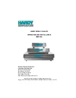
Page 1: ...MS2320 StratosH Scanner Diva Scale Installation and User s Guide ...

Page 2: ...reserved No part of this document may be photocopied reproduced or translated into another language without the prior written consent of HII 2009 Honeywell International Inc All rights reserved Web Address www honeywellaidc com Trademarks Metrologic MetroSelect MetroSet2 StratosSCAN StratosSPHERE StratosSYNC StratosSCOPE StratosSWAP and StratosSCHOOL are trademarks or registered trademarks of Metr...

Page 3: ...rial Number Labels 9 INSTALLATION Quick Installation Outline 10 Site Requirements 10 Vertical Clearance 10 Ventilation and Spacing 10 Service Access 10 Power Installation 11 Checkout Counter Layout Consideration 11 Unpacking the Unit 12 MS2320 Package Warning 13 Lifting the Unit by the Handles 13 MS2320 Mounting Diagram Two Point Support 14 MS2320 Mounting Diagram Three Point Support 15 Cable Inst...

Page 4: ...per Tone and Volume Control 36 The Multi Function Button 36 Startup 37 Power Up Test Mode 37 Configuration Mode 37 SCALE OPERATION Scale Zeroing 38 Calibration 39 Tools Required 39 Scale Calibration Methods 39 Priming the Scale for Calibration lbs kg 40 Scale Calibration Procedure lbs kg with Remote Display 41 Bar Code Calibration Procedure without Remote Display 44 Calibration Verification 48 U S...

Page 5: ...ance 53 TROUBLESHOOTING Troubleshooting Symptom Solution Chart 54 SCANNER AND CABLE TERMINATIONS Scanner Pinout Connections 56 Cable Connector Configurations 58 REGULATORY COMPLIANCE Safety 60 EMC 61 Weights Measures 62 LIMITED WARRANTY 63 PATENTS 64 INDEX 65 CUSTOMER SUPPORT Technical Assistance 67 Product Service and Repair 68 ...

Page 6: ......

Page 7: ...SCAN 6 sided 360 scanning that minimizes product orientation StratosSPHERE Decoding software that reads poor quality and damaged bar codes StratosSYNC Horizontal and vertical scanning zones operate independently from one another GS1 DataBar Decoding Decodes GS1 DataBar GS1 DataBar Limited and GS1 DataBar Expanded symbologies Flash ROM Upgrade latest software enhancements on site Powered Aux Port C...

Page 8: ...r items may be ordered for the specific protocol being used To order additional items contact the dealer distributor or customer service department OPTIONAL ACCESSORIES OPTIONAL ACCESSORIES Part Description 57 57000x N 3 RS232 Interface Cable Straight Cord 57 57004x N 3 RS485 Port 9 Cable Straight Cord 57 57015x N 3 OCIA Interface Cable Straight Cord 57 57200x N 3 USB Full Speed Communication Cabl...

Page 9: ...onal Remote Scale Display 46 00375 Remote Single Line Scale Display lb See Figure 1 46 00376 Remote Single Line Scale Display kg See Figure 1 46 00377 Remote Four Line Scale Display kg See Figure 2 Other Four Line Scale Display currency overlay stickers are available To order additional or replacement items contact the dealer distributor or customer service department Figure 1 Figure 2 All dimensi...

Page 10: ...formance differences To change window type the scanner must be returned to the manufacturer for reconfiguration 46 46889 Vertical Window 46 46806 Diamonex Platter Full Long Size 46 46808 Sapphire Platter Full Long Size Other items may be ordered for the specific protocol being used To order additional items contact the dealer distributor or customer service department 4 ...

Page 11: ...t platter or the vertical window frame Figure 4 PLATTER REMOVAL No hardware or tools are required to remove the platter horizontal scan window see Figure 5 Refer to the Maintenance section of this manual for additional information on platter replacement See caution statement on page 4 Figure 5 LIFT HANDLES REST both thumbs against the vertical window frame for added stability when lifting the unit...

Page 12: ...ume Settings Blue Laser ON Ready to Scan Indicators LED White Good Read Decoding Mechanical L x W x H 508 mm 20 Length 290 mm 11 4 Width 181 mm 7 1 Tower Height Depth Below Counter 100 mm 3 9 Weight with Platter 11 34 kg 24 95 lbs Electrical Voltage Supply 1 5A 5V 1 5A 12V Power Operating 14 25 Watts Standby 3 25 Watts Current Operating 1A 5V 0 75A 12V Standby 0 44 A 5V 0 08A 12V DC Transformers C...

Page 13: ...w Laser Aperture 9 Scale Side Guards 10 Debris Channel 11 Leveling Bubble 12 Handles for Lifting Unit 13 Sealed Calibration Switch Button Cover On a fully installed unit the calibration switch cover should be sealed with either a lead wire or paper seal The seal indicates if the appropriate Federal State and Local Weights and Measures authorities have calibrated the scale See the Scale Operation C...

Page 14: ...BASE MODEL CHARACTERISTICS MS2320 Scanner Diva Scale Dimensions Figure 8 MS2320 Dimensions Connector Panel Figure 9 MS2320 Connector Panel Specifications are subject to change without notice 8 ...

Page 15: ...maintain compliance with applicable standards all circuits connected to the scanner must meet the requirements for SELV Safety Extra Low Voltage according to EN IEC 60950 1 To maintain compliance with standard CSA C22 2 No 60950 1 UL 60950 1 and norm EN IEC 60950 1 the power source should meet applicable performance requirements for a limited power source ...

Page 16: ...e unit to operate without a ventilation fan Honeywell recommends that the temperature surrounding the unit does not exceed 40 C 104 F There should be adequate convection and minimal heat producing equipment in close proximity of the unit A cooling fan with a filter is recommended if there will be a conveyor motor or other heat producing equipment close to the unit that will create a high temperatu...

Page 17: ... Considerations When placing a scanner in a checkout counter the following factors should be considered Items should flow at a distance to the operator that maximizes comfort The operator should not need to stretch or strain to reach for and scan packages The StratosH can scan a bar code on six sides of a package The packages should flow into the scan area that provides the maximum reading perform...

Page 18: ...a safe location until the unit is properly installed into the checkout counter 4 Remove all loose packing materials from the box Figure 12 5 Lift the MS2320 scanner out of the box by carefully grasping both sides near the center of the unit and lifting directly up Refer to Figure 13 for hand placement Important Do not remove the MS2320 scanner from the box by grabbing the shipping foam This can re...

Page 19: ... the scale arms during shipping There is a protective sheet layered behind the Vertical Scan Window which must be removed or the MS2320 scanning ability will be greatly reduced see Figure 16 Figure 16 Removal of Vertical Scan Window Protective Sheet Lifting the Unit by the Handles There are two handles located under the removable platter near the base of the vertical window These handles are provi...

Page 20: ...INSTALLATION INSTALLING THE UNIT IN THE COUNTER MS2320 Mounting Diagram Two Point Support Figure 18 MS2320 Mounting Diagram Two Point Support Specifications are subject to change without notice 14 ...

Page 21: ...INSTALLATION INSTALLING THE UNIT IN THE COUNTER MS2320 Mounting Diagram Three Point Support Figure 19 MS2320 Mounting Diagram Three Point Support Specifications are subject to change without notice 15 ...

Page 22: ...e host with their own separate communication cables Skip to step 6 for a single cable interface where the scale and scanner connect to the host with a single cable 4 Plug the dual interface cable PN 57 57000x N 3 into the 10 pin socket labeled Scale RS232 to Host on the bottom of the StratosH 5 Connect the other end of the dual interface cable PN 57 57000x N 3 to the appropriate communication port...

Page 23: ...st system s RS232 parameters Refer to the MetroSelect Configuration Guide PN 00 02407x under Section G RS232 for Enabling RS232 Mode scan the recall defaults bar code first xxx Specifies international connection See page 3 for a complete listing of power supply options and their part numbers See page 3 for information on optional display types and part numbers See power source caution statement on...

Page 24: ...Full Speed USB RS485 121 interface the USB and RS485 interfaces are not active at the same time Steps 4 and 5 are for dual cable interfaces where the scale and the scanner connect to the host with their own separate communication cables Skip to step 6 for a single cable interface where the scale and scanner connect to the host with a single cable 4 Plug the dual interface cable PN 57 57000x N 3 in...

Page 25: ...iva Scale Configuration Addendum PN 00 02272x under Scanner Configuration Bar Codes Dual Cable Scanner Configuration Bar Codes IBM OEM Full Speed USB Communication Defaults and IBM OEM Full Speed USB Protocols FOR USB SERIAL EMULATION MODE OR KEYBOARD EMULATION MODE ONLY These features can only be used for Dual Cable Applications 11 Configure the StratosH for Bi Directional USB Serial Emulation Mo...

Page 26: ...tional connection See page 3 for a complete listing of power supply options and their part numbers See page 3 for information on optional display types and part numbers See power source caution statement on page 9 of this manual Figure 21 USB Cable Installation Schematic 20 ...

Page 27: ...Speed USB RS485 121 interface the USB and RS485 interfaces are not active at the same time Steps 4 and 5 are for dual cable interfaces where the scale and the scanner connect to the host with their own separate communication cables Skip to step 6 for a single cable interface where the scale and scanner connect to the host with a single cable 4 Plug the dual interface cable PN 57 57000x N 3 into th...

Page 28: ...BM 3 rd Generation 46xx For Dual Cable Applications The IBM 3 rd Generation 46xx and IBM OEM Full Speed USB bar code is located in the MS2x20 Stratos Series Scanner Diva Scale Configuration Addendum PN 00 02272x under Scanner Configuration Bar Codes Dual Cable Scanner Configuration Bar Codes IBM 3 rd Generation 46xx and IBM OEM Full Speed USB xxx Specifies international connection See page 3 for a...

Page 29: ... device A software driver and correct configuration settings are also required for proper communication to occur Steps 4 and 5 are for dual cable interfaces where the scale and the scanner connect to the host with their own separate communication cables Skip to step 6 for a single cable interface where the scale and scanner connect to the host with a single cable 4 Plug the dual interface cable PN...

Page 30: ...tem s OCIA parameters Refer to the MetroSelect Configuration Guide PN 00 02407x under Section I OCIA for Enabling and Setting OCIA Parameters xxx Specifies international connection See page 3 for a complete listing of power supply options and their part numbers See page 3 for information on optional display types and part numbers See power source caution statement on page 9 of this manual Figure 2...

Page 31: ...page 26 3 Connect the angled end of the RS232 AUX cable PN 57 57099x 3 into the 10 pin socket labeled Aux RS232 In on the bottom of the StratosH Important The StratosH series aux port requires the signals transmit receive RTS CTS from the secondary scanner The StratosH s auxiliary port will support 5VDC devices with a 150mA maximum current If the auxiliary device exceeds this specification or requ...

Page 32: ...ALLATION CABLE INSTALLATION SECONDARY HONEYWELL SCANNER See Aux power notes on page 25 See power source caution statement on page 9 of this manual Figure 24 Secondary Scanner Cable Installation Schematic 26 ...

Page 33: ...6 set to ON All StratosH models have a connector labeled EAS In on the bottom of the unit Honeywell has an optional EAS cable PN 52 52511x available for purchase for connection between the Checkpoint Device and the StratosH Figure 25 EAS Cable Connection Bottom of StratosH The following figure shows the location of the EAS deactivation area for the StratosH It is important to pass the entire tag t...

Page 34: ...SCANNER OPERATION SCAN ZONE Figure 27 Checker Side 13 mil Figure 28 Horizontal Left Right 13 mil Specifications are subject to change without notice 28 ...

Page 35: ...SCANNER OPERATION SCAN ZONE Figure 29 Horizontal Direct 13 mil Figure 30 Vertical Direct 13 mil Specifications are subject to change without notice 29 ...

Page 36: ...ected by the IR in the activation area shown below will cause the scanner to exit the power save mode The motor will restart automatically and the laser will turn back on preparing the scanner for bar code recognition decoding and transmission Figure 31 IR Activation Area Perpendicular to Package Flow IR LED Output Refer to the MetroSelect Configuration Guide 00 02407 for additional information on...

Page 37: ... mode Upon exiting configuration mode the scanner will beep three times and the white LED will stop flashing When configured three beeps can also indicate a communications timeout during normal scanning mode When using one code configuring the scanner will beep three times the current selected tone followed by a short pause a high tone and a low tone This tells the user that the single configurati...

Page 38: ...ilure condition If the laser subsystem continues to fail that subsystem horizontal or vertical will be shut down and an error indication will be shown on the Diagnostic Indicator Display This error stays on the display until corrected If the remaining subsystem is still operational scanning will continue using the operational components Flashing Blue and White and Two Razzberry Tones This indicate...

Page 39: ...did not agree with the data last saved Default configuration data is then used and the scanner continues operating This error is also accompanied by three beeps This error will remain during operation as a reminder that this power cycle is scanning against a default generated configuration 06 COMMUNICATION ERROR The RS232 data line is being held active This causes the scanner to read a break signa...

Page 40: ...and this error code will remain on the Diagnostic Indicators 22 LASER 2 RIGHT HORIZONTAL ERROR The right laser in the horizontal scanning subsystem denotes a failure The scanner will try three times to correct the laser operation If the laser error persists and the left horizontal laser 3 is also in error the horizontal scanning subsystem will be shut down and this error code will remain on the Di...

Page 41: ...r and motor OFF after a configured period of non use Any movement detected by the IR will wake the scanner from the power save mode see Figure 31 on page 30 This mode s wake time is slightly longer due to the motor s need to restart 4 Dual Action Power Save Mode 1 Blinks the laser OFF ON after a configured period of non use turns the laser and motor OFF at thirty minute intervals Example If the po...

Page 42: ...is also selectable 9 9 9 9 7 4 Next Volume The Multi Function Button Figure 34 The Multi Function Volume Button Changing the Beeper Volume A short 3 second depression and the beeper volume will change The new volume will be heard The silent no beep volume is also selectable Figure 35 Changing the Beeper Volume Placing the Unit in Laser Motor Off Power Save Mode Long 3 seconds depression The Laser ...

Page 43: ...e types of tests performed at power up 1 Memory tests 2 Hardware setup tests 3 Motor tests 4 Laser tests 5 Configuration tests 6 Interface tests 7 Scale tests These tests are also performed on a periodic basis with the operator alerted to any failures CONFIGURATION MODE All StratosH series scanners have been configured at the factory with a set of default communication protocols Since many host sy...

Page 44: ...ally calibrated see page 39 the scale can be re zeroed by pressing the scale zeroing button on either the unit or on the remote display stand Refer to the figures below for button locations Figure 38 Scale Zero Button Figure 39 Optional Remote Display Keypad 38 ...

Page 45: ...er of the scale to confirm compliance with the relevant Weights and Measures statutes and regulations applicable in your area by checking with the appropriate government agency before placing a newly calibrated unit into service or removing any official seals Tools Required Field Standard 30 0 pound Weight Set or 15 0 kilogram Weight Set Phillips 1 Screw Driver Wire or Paper Seal Type of seal to b...

Page 46: ... is interfering with its freedom to move Assure that no debris is present from daily use of the scanner scale if it has been in service 2 Apply power to the scanner scale See power source caution statement on page 9 of this manual 3 Wait 5 minutes after power up before proceeding Figure 40 Power Up Unit 4 Place the 30 0 lb weight or the 15 kg weight on the center of the scale Allow the weight to s...

Page 47: ...scale there will be either an adhesive label seal or wire sealed cover over the scale calibration button New installation units will only have a factory applied adhesive seal covering the scale calibration button installed To remove the adhesive label seal peel off the label and discard To remove the wire seal cut the wire and discard Fully loosen the security screw and lift off the cover Place th...

Page 48: ...e Display Group 1 Step 8 example shown 6 Verify the weight unit setting Verify the Group 1 Step 8 setting using the table shown below Press the Zero key if correct If the lb Pounds or kg Kilograms basic range setting needs to be changed press the Tare key to scroll through the selectable options Press the Zero key to accept the selected weight unit range Group 1 Step 8 1 8 Selectable Weight Unit R...

Page 49: ... 15kg or 30lb whichever matches the scales selected Weight Unit on the center of the scale platter Wait at least 3 seconds for the scale to stabilize 13 Press the Zero key to accept and begin taking the Full Capacity calibration reading If the scale is unable to capture a stable reading it will not store any value and advance to the next step Verify nothing is touching or interfering with the scal...

Page 50: ...vice or removing any official seals 2 If this is a currently installed scanner scale there will be either an adhesive label seal or wire sealed cover over the scale calibration button New installation units will only have a factory applied adhesive seal covering the scale calibration button installed To remove the adhesive label seal peel off the label and discard To remove the wire seal cut the w...

Page 51: ...he scanner scale will be operating in The scanner will beep once as it enters the bar code calibration mode and the calibration utility will start Unit Calibration Pounds For Kilogram weight units see instructions on page 46 45 9 9 6 0 4 2 Pounds Calibration Figure 50 Entering Bar Code Calibration Mode Pounds If a razz tone sounds an error has occurred Refer to Diagnostic Indicator Display Error C...

Page 52: ... 33 for additional information 6 Make sure there is no load on the scale platter The white LEDs will be used to indicate the current step in the calibration process 7 Calibrate a zero load The white LEDs will blink once periodically Wait 8 to 10 seconds for scale stability and then press the Multi Function Button once After the Multi Function Button has been pressed there will be a short delay fol...

Page 53: ...onds for scale stability and then press the Multi Function Button once After the Multi Function Button has been pressed there will be a short delay followed by five short beeps indicating that the zero load value has been stored Figure 54 10 Calibration process is now complete The scanner will automatically restart and beep one time in about 12 seconds 11 Verify the calibration was successful with...

Page 54: ...0 lbs Shift Test 1 Ensure there is no load on the scale platter and verify the remote display reads 0 00 lbs 2 Place a 15 00 lb weight on the scale platter in the center of zone A see diagram and verify the remote display reads between 14 99 and 15 01 lbs 3 Remove the 15 00 lb weight and verify the display reads 0 00 lbs 4 Repeat steps 2 and 3 for each of the remaining zones B C and D 5 Verify tha...

Page 55: ... and verify the display reads 0 000 kg Shift Test 1 Ensure there is no load on the scale platter and verify the remote display reads 0 000 kg 2 Place a 7 500 kg weight on the scale platter in the center of zone A see diagram and verify the remote display reads between 7 495 kg and 7 505 kg 3 Remove the 7 500 kg weight and verify the display reads 0 000 lbs 4 Repeat steps 2 and 3 for each of the re...

Page 56: ...ecking with the appropriate government agency before placing a newly calibrated unit into service or removing any official seals Type of seal to be used will depend on the guidelines specified by the local Weights and Measures authorities The security seal must only be installed if there were no errors during the scale calibration verification tests Pressure Sensitive Security Seal 1 Temporarily r...

Page 57: ...le sealing screw 3 Tighten the screw and route the wire seal through the holes in the plate and screw Figure 60 Calibration Switch Button Wire Security Seal Assembly 4 Leaving the least amount of slack in the wire loop as possible close the wire seal and verify the seal connection is secure 5 Reinstall the platter Figure 61 Platter Installation These procedures are for MS2320 StratosH Scanner Diva...

Page 58: ...MAINTENANCE PLATTER HORIZONTAL SCAN WINDOW REPLACEMENT Figure 62 Platter Horizontal Scan Window Replacement See replacement parts on page 4 52 ...

Page 59: ...nd vertical output windows will need occasional cleaning For the glass window 1 Spray glass cleaner onto lint free non abrasive cleaning cloth 2 Gently wipe the scanner window For the inner plastic window 1 Use mild soap and water with lint free non abrasive cleaning cloth 2 Gently wipe the scanner window Routinely check and clean the base unit to ensure that no debris is interfering with the plat...

Page 60: ...is disabled Enable the beeper No volume is selected Select a volume The unit powers up but does not beep No tone is selected Select a tone The unit is trying to scan a particular symbology that is not enabled UPC EAN and Code 128 are enabled by default Verify that the type of bar code being read has been selected The unit powers up but does not scan and or beep The unit has been configured for a c...

Page 61: ...ata but the data does not look correct The scanner and host may not be configured for the same interface Check that the scanner and the host are configured for the same interface Characters are being dropped The intercharacter delay needs to be added to the transmitted output Add some intercharacter delay to the transmitted output by using the MetroSelect Configuration Guide PN 00 02407x Aux Port ...

Page 62: ...85 to Host Scanner RS232 to Host Pin Function Pin Function 1 Signal Ground 1 Signal Ground 2 RS232 TX Output 2 RS232 TX Output 3 RS232 RX Input 3 RS232 RX Input 4 Reserved for RS232 Interface 4 RS232 RTS Output 5 Reserved for RS232 Interface 5 RS232 CTS Input 6 Reserved for RS232 Interface 6 RS232 DTR Input 7 IBM B 7 Reserved for RS485 Interface 8 IBM B 8 Reserved for RS485 Interface 9 No Connect ...

Page 63: ...tions Scale to Display Pin Function Pin Function 1 Ground 1 SIG1 2 Scale RS232 TX Out 2 SIG2 3 Scale RS232 RX In 3 SIG3 4 Scale RS232 RTS Out 4 SIG4 5 Scale RS232 CTS In 5 SIG5 6 No Connect 6 SIG6 7 No Connect 7 SIG7 8 No Connect 8 SIG8 9 Reserved 9 No Connect 10 Shield 10 No Connect All signals referenced from the StratosH scanner Specifications are subject to change without notice 57 ...

Page 64: ...d 6 No Connect 7 CTS Input 8 RTS Output 9 No Connect 9 Pin D Type Connector Full Speed USB Cable PN 57 57200x N 3 OR PN 57 57006x N 3 Pin Function 1 PC 5V USB 2 Data 3 Data 4 Signal Ground Locking Type A 57 57200x N 3 Non Locking Type A 57 57006x N 3 RS485 Cable PN 57 57004x N 3 Pin Function 1 Signal Ground 2 IBM A 3 IBM B 4 No Connect 4 Pin SDL OCIA Cable PN 57 57015x N 3 Pin Function 1 Shield Gr...

Page 65: ... Ground 2 RS232 from Aux Secondary Scanner 3 RS232 to Aux Secondary Scanner 4 RTS from Aux Secondary Scanner 5 CTS to Aux Secondary Scanner 6 8 No Connect 9 5VDC Transformer Direct 10 Shield Ground 10 Position Angled Modular Plug This configuration cable was designed to be used with the StratosH auxiliary connector only All signals are referenced from the StratosH scanner All signals are reference...

Page 66: ...nt ne doit en aucun cas essayer d entretenir lui même le scanner ou le laser Ne regardez jamais directement le rayon laser même si vous croyez que le scanner est inactif N ouvrez jamais le scanner pour regarder dans l appareil Ce faisant vous vous exposez à une rayonnement laser qú êst hazardous L emploi d appareils optiques avec cet équipement laser augmente le risque d endommagement de la vision...

Page 67: ... in which case the user will be required to correct the interference at their own expense Any unauthorized changes or modifications to this equipment could void the user s authority to operate this device This device complies with part 15 of the FCC Rules Operation is subject to the following two conditions 1 This device may not cause harmful interference and 2 this device must accept any interfer...

Page 68: ...to provide reasonable protection against harmful interference in a residential installation This equipment generates uses and can radiate radio frequency energy and if not installed and used in accordance with the instructions may cause harmful interference to radio communications However there is no guarantee that interference will not occur in a particular installation If this equipment does cau...

Page 69: ...EXCEPT AS MAY BE OTHERWISE PROVIDED BY APPLICABLE LAW THE FOREGOING WARRANTY IS IN LIEU OF ALL OTHER COVENANTS OR WARRANTIES EITHER EXPRESSED OR IMPLIED ORAL OR WRITTEN INCLUDING WITHOUT LIMITATION ANY IMPLIED WARRANTIES OF MERCHANTABILITY OR FITNESS FOR A PARTICULAR PURPOSE OR NON INFRINGEMENT HII S RESPONSIBILITY AND PURCHASER S EXCLUSIVE REMEDY UNDER THIS WARRANTY IS LIMITED TO THE REPAIR OR RE...

Page 70: ...0 118 No license right or sublicense is granted either expressly or by implication estoppel or otherwise under any Metrologic Honeywell or third party intellectual property rights whether or not such third party rights are licensed to Metrologic and or Honeywell including any third party patent listed above except for an implied license only for the normal intended use of the specific equipment ci...

Page 71: ... 69 error codes 33 34 F failure error codes 33 34 indicator 31 modes 31 32 flow 7 full service access mode 42 function 54 61 62 64 67 G ground 64 67 H handles 5 7 host 31 32 37 54 56 57 63 I immunity 69 indicators 6 audible 31 36 37 54 56 58 59 60 diagnostic 33 34 error codes 33 34 failure 32 33 34 visual 7 31 32 31 32 37 54 55 59 interface 6 9 OCIA 23 24 57 63 64 66 RS232 16 17 57 63 64 66 RS485 ...

Page 72: ... 24 specifications 6 storage 6 switch 27 cover 41 44 50 T test 37 39 51 tone 7 31 36 transformer see power troubleshooting 54 56 U unit of measure 48 49 USB 57 63 V ventilation 6 10 visual 32 voltage 2 6 16 24 volume 7 36 W warranty 54 71 weight 6 40 48 49 weights and measure 39 51 70 white LED see indicators window 4 5 7 10 53 Z zero 7 39 42 49 ...

Page 73: ... com Mexico Telephone 803 835 8000 E mail latechsupport honeywell com Europe Middle East and Africa Telephone 31 0 40 7999 393 Fax 31 0 40 2425 672 E mail hsmeurosupport honeywell com Hong Kong Telephone 852 29536436 Fax 851 2511 3557 E mail aptechsupport honeywell com Singapore Telephone 65 6842 7155 Fax 65 6842 7166 E mail aptechsupport honeywell com China Telephone 86 800 828 2803 Fax 86 512 67...

Page 74: ... 21 3535 9100 Fax 55 21 3535 9105 E mail brservice honeywell com Mexico Telephone 52 55 5203 2100 Fax 52 55 5531 3672 E mail mxservice honeywell com Europe Middle East and Africa Telephone 31 0 40 2901 633 Fax 31 0 40 2901 631 E mail euroservice honeywell com Hong Kong Telephone 852 29536436 Fax 851 2511 3557 E mail apservice honeywell com Singapore Telephone 65 6842 7155 Fax 65 6842 7166 E mail a...

Page 75: ......

Page 76: ...Honeywell Scanning Mobility 9680 Old Bailes Road Fort Mill SC 29707 www honeywellaidc com 00 02271 Rev E December 2009 ...

Reviews: