Honeywell SAT-IDP, User Manual
The Honeywell SAT-IDP User Manual is a comprehensive guide for operating and maximizing the potential of your SAT-IDP device. With step-by-step instructions and detailed illustrations, this manual is available for free download at manualshive.com. Learn how to configure and utilize your device effectively to achieve optimal performance.
Share
Download

Reviews:
No comments
Related manuals for SAT-IDP

A65
Brand: Raymarine Pages: 308

Vulcan Series
Brand: B&G Pages: 198

GWS 10 Marine Wind Sensor
Brand: Garmin Pages: 2
GPS 152 - Marine Receiver
Brand: Garmin Pages: 1
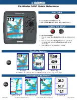
Fishfinder 340C
Brand: Garmin Pages: 2

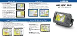
GPSMAP 720
Brand: Garmin Pages: 2
GPSMAP 740
Brand: Garmin Pages: 2
Astro 220
Brand: Garmin Pages: 92
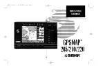
GPSMAP 3205 - Marine GPS Receiver
Brand: Garmin Pages: 2
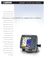
GPSMAP 172
Brand: Garmin Pages: 2

Echomap Plus 40 series
Brand: Garmin Pages: 6

GPSMAP 5215
Brand: Garmin Pages: 4

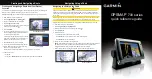
GPSMAP 378 - Marine GPS Receiver
Brand: Garmin Pages: 2
GPSMAP 751
Brand: Garmin Pages: 4
GPSMAP 7012
Brand: Garmin Pages: 2
GPS 16 Series
Brand: Garmin Pages: 1

GP-1871F
Brand: Furuno Pages: 33
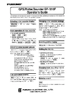
GP-1810F
Brand: Furuno Pages: 2


