background image

® U.S. Registered Trademark
Copyright © 2000 Honeywell Inc. • All Rights Reserved 

INSTALLATION INSTRUCTIONS

69- 1299

S8700B,D-F,J-M Direct Spark

Ignition Controls

APPLICATION

S8700 Direct Spark Ignition Controls are designed for 
use in a wide range of gas-fired appliance applications 
that require direct main burner ignition and flame safety 
control of gas burners. The S8700 is used to ignite the 
main burner, sense the flame and control the gas valve. 
See Table 1 for the model that best meets your 
application needs.

The S8700B,E,J,L models provide single rod flame 
sensing (i.e., the spark rod also acts as the flame sense 
rod). The S8700D,F,K,M models provide dual rod flame 
sensing (i.e., the spark rod and flame rod are separate). 
The S8700J,K,L,M models provide 30-second minimum 
time delay between application of 24V power to the 
control and initiation of the trial for ignition period for 
applications that require prepurge. All models have an 
LED status indicator.

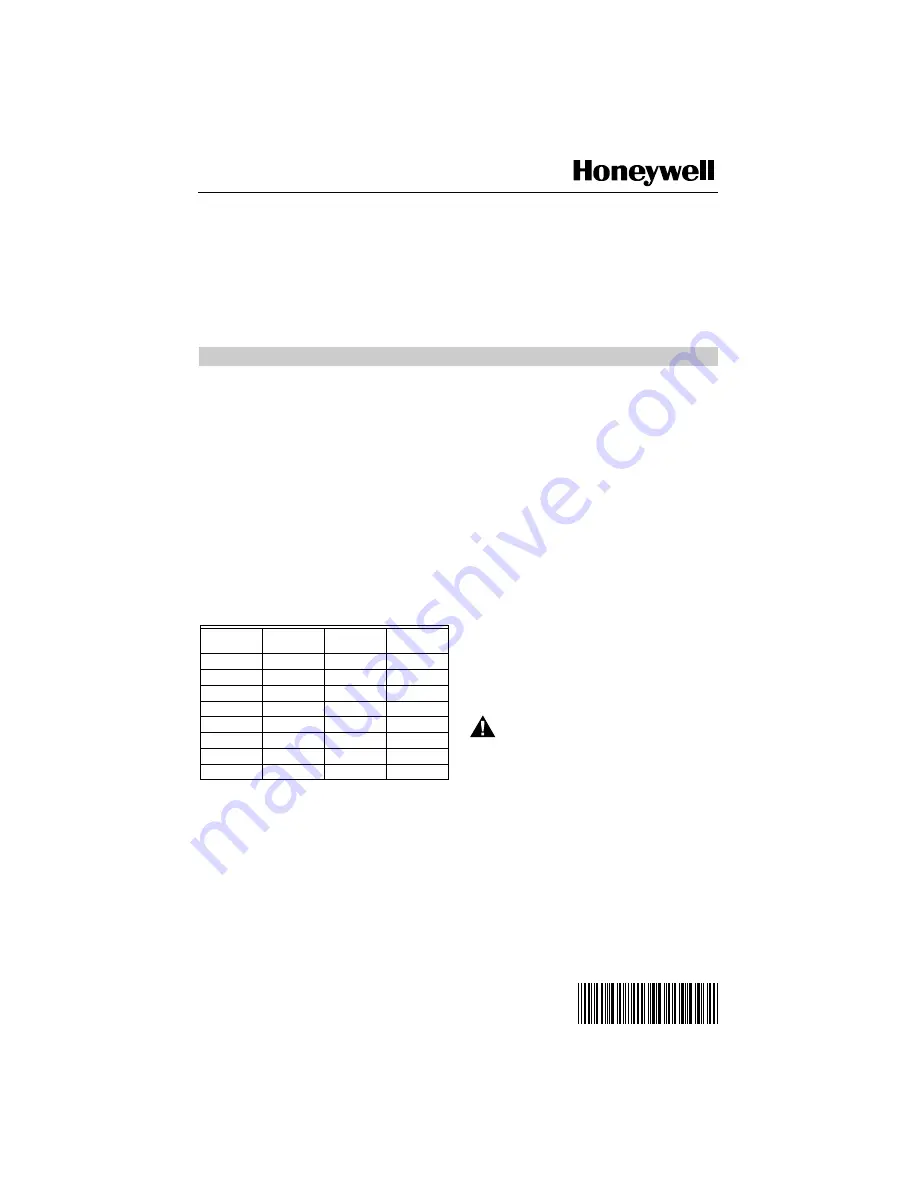
Table 1. S8700 Models.

SPECIFICATIONS

Electrical
Input Voltage: 24 Vac (20.5 Vac minimum to 28.5 Vac 

maximum) at 60 Hz.

Current Draw: 0.15A maximum in run mode at 24 Vac.
Thermostat Anticipator Setting: 0.15A plus actual valve load.
Valve Output: 2.0A maximum run; 6.0A maximum 

inrush at 24 Vac.

Alarm Output: 0.5A maximum resistive load (Output is 

positive phase, one-half wave rectified, 24 Vac).

Spark Output: 14 KV minimum into 25 picofarad 

capacitive load.

Environmental
Ambient Operating Temperature: -40°F to +175°F

 (-40°C to +79°C).

Relative Humidity: 5% to 95% at 95°F (35°C), 

noncondensing.

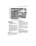
Ignition Sequence/Flame Sense
Prepurge: See Table 1.
Ignition Trials to Lockout: See Table 1.
Trial for Ignition Times: 4.6, 6.6, 11.1 or 21.1 second 

nominal available.

Between Trial Purge: 30 second minimum 

(S8700E,F,L,M only).

Auto Reset from Lockout: 60 minutes minimum 

(S8700E,F,L,M only).

Flame Failure Re-ignition Time: 0.8 second maximum 

at 1 microamp flame current.

Flame Current:
Minimum Threshold: 1 microamp.
Appliance Application: 2.5 microamp minimum recom-

mended under all appliance operating conditions.

Approvals:
CSA International Design Certified to ANSI Z21.20, 

Report Number C2030026.

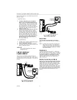
PLANNING THE INSTALLATION

WARNING

Fire or Explosion Hazard.
Gas leaks can cause property damage, 
severe injury or death.

Follow these warnings exactly:

Plan the installation using the following outline.

Plan for frequent maintenance as described in 
the Maintenance section.

Review the following conditions that apply to your 
specific installation and take the precautionary steps 
suggested.

Model

Flame 
Sense

Trials for 

Ignition

Prepurge 

(seconds)

S8700B

1-rod local

1

S8700D

2-rod remote 1

S8700E

1-rod local

3

S8700F

2-rod remote 3

S8700J

1-rod local

1

30  minimum

S8700K

2-rod remote 1

30  minimum

S8700L

1-rod local

3

30 minimum

S8700M

2-rod remote 3

30 minimum

Summary of Contents for S8700 Series

Page 1: ...tput is positive phase one half wave rectified 24 Vac Spark Output 14 KV minimum into 25 picofarad capacitive load Environmental Ambient Operating Temperature 40 F to 175 F 40 C to 79 C Relative Humidity 5 to 95 at 95 F 35 C noncondensing Ignition Sequence Flame Sense Prepurge See Table 1 Ignition Trials to Lockout See Table 1 Trial for Ignition Times 4 6 6 6 11 1 or 21 1 second nominal available ...

Page 2: ... to protect the control Proper insulation or shielding should be provided by the appliance manufacturer verify proper air circulation is maintained when the appliance is installed System Requirements S8700 system requirements Q347A Spark Igniter and Q354A Flame Sensor or a Q366 with separate spark igniter and flame sensor mounted on a common bracket Equivalent ignition hardware may be used Honeywe...

Page 3: ...ontrol 1 Connect the system components to the S8700 terminals as shown in the wiring diagrams Fig 2 and 3 Refer to the heating appliance manufac turer s instructions for wiring any other auxiliary controls 2 Adjust the temperature control heat anticipator if provided to match the system current draw The current draw equals the total current required for the S8700 0 15A plus the gas valve and all o...

Page 4: ...t System 1 Turn on the power and the gas supply 2 Set the temperature control to call for heat and watch for a spark at the igniter S8700B D E F models have no delay on start up S8700J K L M models have a predetermined delay on start up for prepurge Check that the system starts as follows Prepurge delay if provided spark turns on gas valve opens at once and burner ignites after gas reaches the mai...

Page 5: ...the reset normal condition and interrupts the spark ignition circuit Should the current flow be interrupted i e flame out condition the spark will be re initiated immediately and a normal trial for ignition will occur If the main burner lights and proves a normal run will occur If the main burner does not light and prove the S8700 goes into lockout The S8700 keeps the gas control main valve open a...

Page 6: ...gnition circuit do the following 1 Shut off the gas supply to the gas control 2 Be sure system power supply delivers proper volt age to the S8700 during the ignition cycle 3 Disconnect the ignition cable at the S8700 spark terminals to isolate the circuit from the spark igniter or igniter sensor Prepare a short jumper lead using heavily insulated wire such as ignition cable Fig 4 S8700B D J K one ...

Page 7: ...y even though operation is normal at time of checkout Therefore if nuisance shutdowns have been reported be sure to check ground connections Electrical ground connections at the spark igniter or igniter sensor and the S8700 must be clean and tight If leadwire is damaged or deteriorated use only a No 14 or No 18 gauge moisture resistant thermoplastic insulated wire with 221 F 105 C minimum rating a...

Page 8: ...ions as described in the following sections Fig 6 S8700D F K M dual rod flame current measurement Fig 7 S7800B E J L single rod flame current measurement Burner Flame The flame sensor must be constantly immersed in flame Check the burner flame conditions as shown in Fig 7 NOTE Note If the main burner flame is fluctuating or lifting off the main burner intermittent flame signals can be generated Ad...

Page 9: ...ce or repair the troubleshooting sequence should be repeated until normal system operation is obtained NOTE When the appliance is in the lightoff mode ignition spark and the gas control are energized only during the trial for ignition which can last from four to 21 seconds depending on the S8700 model It will be necessary to recycle the call for heat to the control while performing this troublesho...

Page 10: ...SPARK GAP IS NOT TOO SMALL OR TOO LARGE ALL OK REPAIR REPLACE AS NECESSARY REPAIR REPLACE AS NECESSARY IF S8700 GOES INTO LOCKOUT RESET SYSTEM CHECK FOR 24 VAC BETWEEN S8700 VALVE AND VALVE GND TERMINALS DURING TRIAL FOR IGNITION CHECK GAS SUPPLY GAS CONTROL AND GAS CONTROL WIRING REPAIR REPLACE AS NECESSARY IF S8700 GOES INTO LOCKOUT RESET SYSTEM CHECK ALL IGNITION CABLE BURNER GROUND WIRING AND ...

Page 11: ...11 69 1299 ...

Page 12: ...Home and Building Control Honeywell Inc Honeywell Limited Honeywell Limitée Honeywell Plaza 155 Gordon Baker Road P O Box 524 North York Ontario Minneapolis MN 55408 0524 M2H 3N7 Printed in U S A on recycled paper containing at least 10 post consumer paper fibers ...

Reviews: