background image

PRODUCT DATA

63-2582

® U.S. Registered Trademark
Copyright © 2002 Honeywell •  All Rights Reserved 

R7195A,B

Motor Positioner

APPLICATION

The R7195A,B Motor Positioner is a single channel solid state 

proportioning amplifier that will accept an output signal from a 

controller to position a reversing control motor with a 135-ohm 

or 1000-ohm feedback slidewire. Motors with slidewires that 

have resistances other than 135 ohms or 1000 ohms will be 

shunted to one of these two values. 

The R7195A Motor Positioner is factory-adjusted to accept a 4 

to 20 mA input. The R7195B Motor Positioner is 

factory-adjusted to accept input from a 135-ohm 

retransmitting slidewire.

FEATURES

• Accepts 4-20 mA or 135-ohm signal to provide position 

proportional control of M944 Modutrol® Motor without 

balance relay and M940A,B Actionator.

• Heavy duty case.
• Mounts directly on M940 Actuator.
• Solid state design extends product life and reliability.
• Zero, span and deadband adjustments allow motor to 

be field adjusted to various input ranges: i.e., split 

ranging.

• Hard Manual feature allows operator to override the 

controller (4-20 mA or 135-ohm input) action to open or 

close fully the final control element.

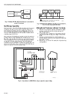
• Reversing direction of motor can be accomplished by 

simple wiring change of R7195.

• Output from one R7355 4-20 mA DialaTrol can operate 

up to eight R7195 Positioners and associated M944 or 

M940 Actuators.

• Output from one 135-ohm Series 90 Controller can 

operate up to five R7195B Motor Positioners.

• Span and zero adjustment do not interact with each 

other so each adjustment can be made independently 

without having to readjust the other parameter.

• Can operate with motor feedback slidewire between 

100 and 1000 ohms.

Contents

Application ........................................................................

1

Features ...........................................................................

1

Specifications ...................................................................

2

Installation ........................................................................

3

Wiring ...............................................................................

3

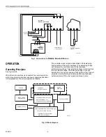
Operation ..........................................................................

6

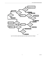
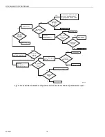
Service and Troubleshooting ............................................

7

Summary of Contents for R7195A

Page 1: ...ctionator Heavy duty case Mounts directly on M940 Actuator Solid state design extends product life and reliability Zero span and deadband adjustments allow motor to be field adjusted to various input ranges i e split ranging Hard Manual feature allows operator to override the controller 4 20 mA or 135 ohm input action to open or close fully the final control element Reversing direction of motor ca...

Page 2: ...o 66 C Slidewire Resistance 135 ohms or 1000 ohms Input Range R7195A 4 20 mA Adjustments Zero 0 8 to 16 8 mA Span 2 0 to 20 0 mA Deadband 1 to 5 Factory Settings Zero 4 0 mA input 0 to 5 feedback potentiometer position Full Scale 20 mA 95 to 100 feedback potentiometer position Input Range R7195B 135 ohm retransmitting slidewire input Adjustments Zero 0 to 80 of slidewire input Span 12 5 to 125 of ...

Page 3: ...Refer to Fig 1 and layout of the centers of the mounting hole locations on the mounting surface 1 Use a center punch and hammer to mark the locations for drilling 2 Depending on the characteristics of the mounting surface drill clearance holes No 23 bit for No 6 machine screws or starting holes No 37 bit for No 6 self tapping screws 3 Place the positioner on the surface so that the mounting holes ...

Page 4: ...tentiometer Fig 3 Multiple R7195B Motor Positioners connected to one 135 ohm input potentiometer Wiring Motor Positioner to Motor Terminals 1 Refer to wiring diagrams and documentation supplied with the motor to connect the motor positioner for specific applications 2 To avoid inductive interference to the internal circuitry separate the leads carrying line voltage from all other leads 3 Provide c...

Page 5: ... G L2 L1 2 3 1 B W R G 3 2 1 6 5 4 GROUND NEUTRAL HOT R7195 SUPPLY M940A MOTOR TERMINALS TO 4 20 mA INPUT B W R CW 135 OHM POTENTIOMETER INPUT M20790 R7195A B MOTOR POSITIONER 5 4 6 G L2 L1 2 3 1 B W R 1 L1 L2 2 3 R Y T G GROUND NEUTRAL NEUTRAL HOT HOT R7195 SUPPLY M944 G S LINE VOLTAGE MOTOR TERMINALS TO 4 20 mA INPUT B W R CW 135 OHM POTENTIOMETER INPUT M20791 ...

Page 6: ...the error signal voltage The balancing bridge circuit will amplify the error signal causing a Triac switch to fire This will energize a motor winding and will re position the feedback potentiometer until the error signal is reduced to zero Fig 8 Block diagram R7195A B MOTOR POSITIONER 5 4 6 G L2 L1 2 3 1 B W R 1 2 3 L1 L2 24 VAC 120 VAC Y T G GROUND NEUTRAL HOT R7195 SUPPLY M944B E MODUTROL MOTORS...

Page 7: ...tween the input signal and the slidewire signal is zero SERVICE AND TROUBLESHOOTING Calibration Procedure NOTE The R7195 Motor Positioner is calibrated at the factory for a 4 20 mA input signal for the R7195A and a 135 ohm potentiometer input for the R7195B Therefore do not calibrate the motor positioner unless the input signal desired is something other than 4 20 mA R7195A or 135 ohms R7195B To c...

Page 8: ...omponent failures are listed below a Shorted triac switches Q3 and Q4 b Q3 and Q4 break over at less than rated voltage c Q3 and Q4 do not fire d MOV CR12 shorts 5 If the logic diagram does not identify your system related problem the failure is not in the output circuit and the controller should be replaced or you may use the schematic to troubleshoot the board NOTE If your motor motor controller...

Page 9: ...O 1 REPLACE Q4 REPLACE Q4 DID MOTOR DRIVE AT NORMAL SPEED YES NO IS VOLTAGE LESS THAN 10V YES NO REPLACE Q3 A4 R28 R29 YES YES NO NO YES DID MOTOR DRIVE OPEN REPLACE Q4 REPLACE Q4 A5 R31 R32 REPLACE CR12 REPLACE Q3 M20795 NO YES SHORT TERMINALS B TO W CONNECT OPERATING VOLTAGE OPEN INPUT FROM CONTROLLER MEASURE AC VOLTAGE AT TERMINALS 1 AND L2 IS VOLTAGE LESS THAN 10V REPLACE Q3 YES NO YES NO YES ...

Page 10: ...AGE AT TERMINALS L2 TO 1 REPLACE Q4 REPLACE Q4 DID MOTOR DRIVE AT NORMAL SPEED YES NO IS VOLTAGE LESS THAN 10V YES NO REPLACE Q3 A4 R28 R29 YES YES NO NO YES DID MOTOR DRIVE OPEN REPLACE Q4 REPLACE Q4 A5 R31 R32 REPLACE CR12 REPLACE Q3 M20796 NO YES OPEN INPUT W CONNECT OPERATING VOLTAGE SHORT R W MEASURE AC VOLTAGE AT TERMINALS 1 AND L2 IS VOLTAGE LESS THAN 10V REPLACE Q3 YES NO YES NO YES DID MO...

Page 11: ...11 63 2582 ...

Page 12: ...ario M1V 4Z9 R7195A B MOTOR POSITIONER By using this Honeywell literature you agree that Honeywell will have no liability for any damages arising out of your use or modification to the literature You will defend and indemnify Honeywell its affiliates and subsidiaries from and against any liability cost or damages including attorneys fees arising out of or resulting from any modification to the lit...

Reviews: