


-- 1 --
462 06 1211 00
3/17/06
Installation Instructions For Natural Gas Conversion
(Kit Part No. 1173865)
This kit is designed for conversion to Natural Gas.
2001 to 4000 ft 4001 to 5000 ft
5001 to 6000 ft
6001 to 7000 ft
7001 to 8000 ft
8001 to 9000 ft 9001 to 10000 ft
44
1173863
45
46
47
47
48
48
49
44
1173863
45
46
47
47
48
48
49
44
1173863
45
46
47
47
48
48
49
44
1173863
45
46
47
47
48
48
49
44
1173863
45
46
47
47
48
48
49
44
1173863
45
46
47
47
48
48
49
41
1173865
43
43
43
44
44
45
46
42
1173865
43
43
44
44
45
46
47
42
1173865
43
43
44
44
45
46
47
44
1173863
45
46
47
47
48
48
49
44
1173863
45
46
47
47
48
48
49
44
1173863
45
46
47
47
48
48
49
41
1173865
43
43
43
44
44
45
46
42
1173865
43
43
44
44
45
46
47
42
1173865
43
43
44
44
45
46
47
44
1173863
45
46
47
47
48
48
49
44
1173863
45
46
47
47
48
48
49
44
1173863
45
46
47
47
48
48
49
41
1173865
43
43
43
44
44
45
46
42
1173865
43
43
44
44
45
46
47
42
1173865
43
43
44
44
45
46
47
44
1173863
45
46
47
47
48
48
49
44
1173863
45
46
47
47
48
48
49
44
1173863
45
46
47
47
48
48
49
41
1173865
43
43
43
44
44
45
46
42
1173865
43
43
44
44
45
46
47
42
1173865
43
43
44
44
45
46
47
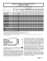
Note: "**" or "***" may be any combination of numbers and/or letters in the model number.
Note: The orifice sizes in the chart above derate the input rate at 4% per 1000 feet above sea level for altitudes exceeding 2000 feet above sea level.
Natural gas data is based on .60 specific gravity, a heating value of 1030 Btu/cubic foot, and 3.5 "W.C. manifold pressure.
For fuels with different specific gravity and/or different heating values, consult the National Fuel Gas Code ANSI Z223.1 - 2002/NFPA 54-2002 or
National Standard of Canada, Natural Gas and Propane Installation Code CSA B149.1-00.
PGF3**120
PGF3**140
PGF3**040
PGF3**060
PGF3**080
PGF3**100
PGS***K140F, GPSM**K140
Orifice Drill #
(Field-Supplied)
PGS***K040F, GPSM**K040
PGS***K060F, GPSM**K060
PGS***K080F, GPSM**K080
PGF***K040F, GPFM**K040
PGF***K120F, GPFM**K120
PGX3, PDX3 (All Sizes)
Orifice Drill #
(Field-Supplied)
PGF***K100F, GPFM**K100
PGS***K100F, GPSM**K100
PGS***K120F, GPSM**K120
PGC***K140F, GPCM**K140
PGF***K060F, GPFM**K060
Note: If converting from LP gas to Natural gas at altitudes exceeding 2000 feet above sea level, conversion kit (Part #330732-401) is required for proper conversion. For all models, except PGX3, PDX3, and PGF3, a .018 pilot
orifice (Part # 5032110) is also required.
Orifice Drill #
(Field-Supplied)
Orifice Drill #
(Field-Supplied)
Orifice Drill #
(Field-Supplied)
Model Number
Orifice Drill #
Kit Number
Orifice Drill #
(Field-Supplied)
PGC***K060F, GPCM**K060
PGC***K080F, GPCM**K080
PGC***K100F, GPCM**K100
PGC***K120F, GPCM**K120
Natural Gas Orifice Kits and Sizes
Table 1
PGF***K140F, GPFM**K140
PGAA, PGMD (All Sizes)
PGAD, PGME (All Sizes)
PGC***K040F, GPCM**K040
Orifice Drill #
(Field-Supplied)
0 to 2000 ft
Elevation Above Sea Level
PGF***K080F, GPFM**K080
Parts List
,
Kit # 1173865
Description
Part #
Qty
Burner Orifice #41
1096942
7
Burner Orifice #42
1011351
7
Pilot Orifice (0.018)
503211
1
Honeywell Conv. Kit #396222
1172952
1
Label, Natural Gas Conversion
1173866
1
Label, Field Conversion
1009678
1
Instructions
462 06 1211 00
1
SAFETY REQUIREMENTS
Recognize safety information. This is the safety--alert symbol
.
When you see this symbol in instruction manuals be alert to the
potential for personal injury.
Understand the signal words DANGER,WARNING, or CAUTION.
These words are used with the safety--alert symbol. DANGER
identifies the most serious hazards, those that will result in severe
personal injury or death. WARNING signifies a hazard that could
result in personal injury or death. CAUTION is used to identify
unsafe practices that may result in minor personal injury or product
and property damage. NOTE is used to highlight suggestions that
will result in enhanced installation, reliability, or operation.
Installing and servicing heating equipment can be hazardous due
to gas and electrical components. Only trained and qualified
personnel should install, repair, or service heating equipment.
Untrained service personnel can perform basic maintenance
functions such as cleaning and replacing air filters. All other
operations must be performed by trained service personnel. When
working on heating equipment, observe precautions in the
literature, on tags, and on labels attached to or shipped with the
appliance and other safety precautions that may apply.
Follow all safety codes. In the United States, follow all safety codes
including the National Fuel Gas Code (NFGC) ANSI
Z223.1--2006/NFPA 54--2006. In Canada, refer to the of the
National Standard of Canada Natural Gas and Propane
Installation Code (NSCNGPIC) CSA B149.1--05. Wear safety
glasses and work gloves. Have fire extinguisher available during
start--up and adjustment procedures and service calls.
These instructions cover minimum requirements and conform to
existing national standards and safety codes. In some instances,
these instructions exceed certain local codes and ordinances,
especially those that may not have kept up with changing
residential construction practices. We require these instructions
as a minimum for a safe installation.
!


