11”
Fold
Fold
Fold
17”
Fold
Fold
Fold
EN | 2
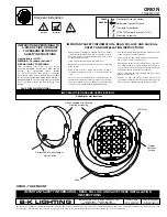
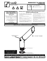
INSTALLATION
CAUTION:
Before beginning installation turn off the circuit breaker and light switch.
STEP 1
STEP 3
RECOMMENDED:
Wrap each wire nut with electrical tape (not included) after wires have
been attached.
Note:
Avoid aiming the motion sensor at:
• Objects that change temperature rapidly to prevent false triggering, such as heating vents
and air conditioners.
• Moving objects such as trees and street trafc.
The lamp head (Part G) can be adjusted up/down and left/right for optimal lighting coverage. The
motion sensor (Part J) can be adjusted up/down toward desired detection area.
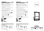
EN | 1
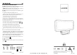
SAFETY INFORMATION
PRE-INSTALLATION
• To reduce the risk of electrical shock or other personal injury, ensure the power is turned
OFF at the fuse or breaker box before making any electrical connections.
• For outdoor use only.
• Must be connected to 120 volt, 60 Hz power source.
• Fixture should be mounted to a grounded junction box marked for use in wet locations.
• Suitable for wall mount.
• NOT suitable for ground locations. Minimum of 6 feet or higher.
• Wall lantern should be installed by a qualified electrician or person experienced with
household wiring. The electrical system, and method of electrical connection of the fixture,
must be in accordance with the National Electrical Code and local building codes.
PLANNING INSTALLATION
• Turn off the electrical power at the fuse or circuit breaker box before installing or servicing
any part of this fixture.
• Carefully remove the fixture from the carton and check that all parts are included. Be careful
not to misplace any of the screws or parts needed for installing the fixture.
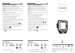
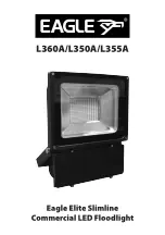
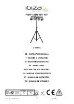
HARDWARE INCLUDED
EN | 3
F:
Washer (1)
Ø8.5 mm x 1 mm
A:
Phillips Head Screws (2)
8-32UNC x 20
WARNING:
Read all safety precautions and installation instructions carefully before installing or
servicing this fixture. Failure to comply with these instructions could result in a potentially fatal electric
shock, fire, and/or property damage.
IMPORTANT:
lisez attentivement toutes les précautions de sécurité et les installations avant
d'installer ou de réparer ce luminaire. Le non respect de ces instructions peut entraîner un choc
électrique et / ou des dégâts matériels potentiellement fatals.
SUITABLE FOR WET LOCATIONS ! CONSULT A QUALIFIED ELECTRICIAN TO ENSURE
CORRECT BRANCH CIRCUIT CONDUCTOR! MINIMUM 90° C SUPPLY CONDUCTORS!
ADAPTÉ AUX LIEUX MOUILLÉS! CONSULTER UN ÉLECTRICIEN QUALIFIÉ POUR
ASSURER UN CONDUCTEUR DE CIRCUIT DE BRANCHE APPROPRIÉ! CONDUCTEURS
D'ALIMENTATION MINIMUM DE 90° C!
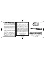
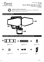
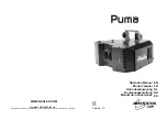
G - Lamp Head
H - Screw Nut
I - Lamp base
J - Motion Sensor
PARTS
C:
Waterproof pad (1)
Ø132 mm x 3 mm
D:
Mounting Bracket (1)
100 mm x 21 mm
B:
Wire Nut (3)
P2 10 mm x 17.2 mm
E:
Phillips Head Screws (1)
M5 x 42mm
G
G
I
J
J
H
(Figure 1)
(Figure 2)
1.
OPERATION
Position the mounting bracket (Part D) to the junction box (Not Included) and secure using
screws (Part A). The AC wires through the waterproof pad (Part C), and the waterproof pad
(Part C) can be pasted to the lamp base (Part I). Then connect the AC wires to the
corresponding wires (BLACK to BLACK, WHITE to WHITE and GROUND to GROUND) in the
junction box using the wire nuts (Part B). (Figure 1)
STEP 2
Making screw (Part E) through the washer (Part F) and the hole of the lamp base (Part I),
then fix the lamp to the mounting bracket, adjust the lamp to the proper position and
tighten the screw.
Note:
The lamp heads should be installed horizentally.
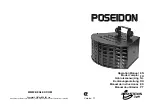
FUNCTION SWITCH:
K - Motion sensor sensitivity switch
L - Timer switch
M - Link button
1. Motion sensor sensitivity switch (Part K), detection distance can be adjusted to
Min. 6.6 feet (2m), Max. 39.4 feet (12m).
2. Timing switch (Part L), the TEST option is used for adjust detection distance during
the day time installation, the light will last 12s when activated.
After your test finished, select your favorite motion activated duration time,
1min/5min/10min
.
Note: If you go back to TEST mode and light isn’t lit, try again after power off/on.
3. Link set-up:
a. Can be connected more than 2 lights, make sure all the light are power on and
move to TEST position, select one as the parent light and others as the child lights.
b. Press the link button (Part M) of the child light to flashing status, keep on the link
button (Part M) for 3 seconds of parent light and waiting for code matching, all lights
flashing, once the parent light and child light stop flashing or being on, it confirms
code matching is completed and products are linked, release button.
c. When any of the lights are triggered by motion detector, all lights will activate.
Note:
When light triggered by motion, detection angle is 180°. Light's use radio
frequency technology to link, and should not be greater than 98 feet between the
neighboring/adjacent lights.
If you buy a new light and want to link , you can re-set up.
Note:
Affected by the installation environment, the lamp will be delayed to light.
It is a normal case.
4. Relieve linkable function: keep on the link button (Part M) for 3 seconds, the light
will work independently.
L
K
M
B
D
A
C
E
F