background image


1/6 


S-8109.1-TAD-FTT-ENG           Rev. A.2          01/2018 

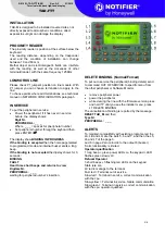
Terminal with back light and display. 


TAD-FTT 

     
FEATURES 

Multi-functional terminal for the management of central-
net 
 
Features: 

  Graphic  display  128x64  pixel,  8  lines  of  21 

Characters 

  Backlight 14 keys keyboard with tricolor led for each 

key. 

  8  function  keys  vith  tricolor  LEDs  built-in,  that  can 

be used in 4 pages (total 32 functions – 32 tri-color 
LED) 

  4  Tri-color  LED  for  system  messages  (3 

programmable) 

  Integrated proximity reader (EM4100) 

  Internal clock calendar 

  Operation in degraded-mode, 10000 events storage 

  2 digital input multi-balance 

  2 digital output O/C 

  1 Programmable buzzer 

  1 Optical tamper  

  1 temperature sensor  


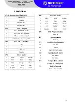
Terminal is prepared to connect: 

  2 ISO7811/2 compatible badge reader  

  Additional  proximity  reader  AT-E  and  terminal 

emulator AT-I 

  Additional  proximity  reader  AEI3  and  terminal 

emulator AEI3-I  

  RADIOCAR  radio  receiver  for  TR-2P  and  TR-3P 

radio-controls 

  1  external  MGP-E  module  with  a  double  balance 

input  and  a  5A  relay  output  (excludes  an  input 
output O/C) 

  Displaying 32 functions selected by menù 


APPLICATIONS 

Depending on programming, TAD-FTT can be used as: 

  System terminal 

  Access control terminal 

  Time and attendance terminal 


OFF LINE MODE 

When  communication  with  the  control  panel  is  missing, 
terminal can manage the controlled passage by itself or 
together with another terminal. MGP outputs and inputs 
used  for  actuator,  local  forcing  alarm,  sensor  and 
manual  door  open  command  are  managed  locally. 
Events generated in offline mode are sent to the control 
panel when connection is established again 

N.B.


For  the  central  with  fw  6.xx  are  handled  only  the 

PIN, the first trasponder and badge of each operator. 
Remote controls and second bedge or trasponder are not 
stored in local memory 
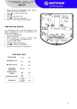
 

MOUNTING 

The wheelbase of fixing holes is suitable for 503 boxes. It 
can also be fixed through dowels for 3,9mm maximum 
diameter screws. Fix the rear panel of the box to the wall, 
connect cables, bring the terminal next to the rear panel 
taking care of cables disposition in order not to touch 
electrical components, then insert the case on the rear 
panel on one side first, then on the other, pressing until it 
is blocked. 


Warning 
 

Avoid flexing or bending the internal board and do not 
use metallic tools when it is powered. 
Before proceeding with electrical connections remove 
power. 
The connectors can be used both the input cables to the 
top and down. 
During the wiring the connector to check the direction in 
which they were wired to avoid errors in links. 
During  connectors’  insertion/removal,  fix  the  board  to 
avoid bending, and check the wire position. 
To  open  the  plastic  container  to  unlock  the  block  with 
screwdriver form 5 to 8 mm. 


Summary of Contents for Notifier TAD-FTT

Page 1: ...nel is missing terminal can manage the controlled passage by itself or together with another terminal MGP outputs and inputs used for actuator local forcing alarm sensor and manual door open command are managed locally Events generated in offline mode are sent to the control panel when connection is established again N B For the central with fw 6 xx are handled only the PIN the first trasponder an...

Page 2: ...ed to programmed mode and internal buzzer emits a long beep If the binding is not accepted the dipslay shows for 3 seconds BINDING FAULT Hear three short beeps and returns to view Digitare Nr PERIPHERAL _ _ _ waiting for peripheral number s insertion DELETE BINDING Normal Forced To put out o service the peripheral binding delete send to command OUT OF SERVICE to specific menu from the other periph...

Page 3: ... recognized are highlighted by a S Press to confirm the configuration Press to return at the normal operation RECEPTION TRANSMISSION FIRMWARE Remove peripheral power Power the peripheral While viewing the Firmware versione press and hold untill you see installer menù Press L3 RECEPTION FIRMWARE if you want to receive the firmware from another peripheral Press L4 TRASMISSION FIRMWARE If you want se...

Page 4: ...ady calibrated on the factory configuration to make a new calibration or to adapt on the installation Remove peripheral power Power the peripheral While viewing the Firmware versione press and hold untill you see installer menù Press L6 SENS TEMP With adjust the teperature press to confirm the configuration Press to return at the normal operation TECHNICAL DATA Power Supply 9 30 Vcc Standby curren...

Page 5: ...al line 1 Lon 2 Lon 3 Local Line 4 Negative JP4 Direct reader 1 DATA Brown Orange 2 CLS Red Yellow 3 CLK Orange Brown 4 5 V Yellow Red 5 Negative Green Black JP5 Opposite reader 1 DATA Brown Orange 2 CLS Red Yellow 3 CLK Orange Brown 4 5 V Yellow Red 5 Negative Green Black JP6 USB Programmation Riserved JP7 Programmation Riserved P1 Lon Line Configuration 1 2 Lon Bus 2 3 Lon Free A Open No Termina...

Page 6: ...l B n 85 Centergross Tel 051 864855 Fax 051 6647638 E mail notifier bologna notifier it 50136 Firenze Via B Telesio 15 Tel 055 69706 Fax 055 556529294 00118 Roma Via Del Casale Santarelli 51 Tel 06 7988021 Fax 06 79880250 E mail notifier roma notifier it 80143 Napoli Palazzo Prof Studi Centro Direzionale Isola E2 Scala B Piano 5 Tel 081 7879398 Fax 081 7879159 E mail notifier napoli notifier it 70...

Reviews: