iPCAM-WI2 Wireless Internet Video Camera – Quick Installation Guide
For Online Support visit: http://www.security.honeywell.com/hsc/resources/MyWebTech/
General Information
Antenna
This guide provides information on installing and setting up Honeywell's iPCAM-WI2 (white)
and iPCAM-WI2B (black) Cameras. This camera is ideal for monitoring your home, business
or public facilities. Some major features of this camera are:
Wired or Wireless communications to a router or access point. Wireless communications
utilizes the 802.11b/g protocol with WPS security. WPS (Wi-Fi Protected Setup) is a
standard for easy setup of a secure wireless network.
Color video can be monitored through your Total Connect remote services account. Up to
6 cameras can be used.
IMPORTANT: This camera is for indoor use only. DO NOT mount this camera within one [1]
foot of any wireless device.
To utilize this camera, you must have:
An AlarmNet account for a GSM or Internet communicator, or a “Video Services Only”
account.
Total Connect account. (If an account does not exist, the dealer should use the AlarmNet
Direct website to set up a Total Connect account for the customer.)
Internet access with a router capable of DHCP hosting. For wireless, the router must also
support one button WPS data encryption. If this is not available, order the Honeywell WAP
Wireless Access Point for connection to your router.
PACKAGE CONTENTS
Camera and Stand
Power Transformer
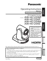
Component Identification
POWER
NETWORK
POWER
LAN
WPS
SPEAKER
OUT
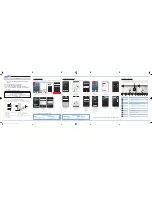
Planning the camera installation
A camera installation can be as simple as installing one camera, or up to six cameras per
Total Connect account. In large installations it may include a mix of wireless, and wired cameras.
The installer should work closely with the customer to achieve a satisfactory installation.
W
ire
le
ss
R
an
ge
35
-5
0f
t.
ra
di
us
W
ire
les
s R
an
ge
35
-5
0f
t.
ra
diu
s
Modem
AlarmNet
via the
Internet
Router
Ethernet cable
300ft. max.
Ethernet cable
300ft. max.
WAP #1
WAP
#2
Wired
Camera
Ethernet cable
300ft. max.
75 ohm cable for
NTSC video camera
NTSC Video Camera
~ 100ft. maximum cable length.
Refer to the camera manufacturers
installation guide.
Lens – Fixed lens requires no
focusing. Clean with a soft
tissue and lens cleaner.
POWER (green)
Blinking – Camera is booting.
Steady On – Camera is ready.
WPS Button – Used during
setup to configure wireless
encrypted connectivity.
LAN Connector – Used for
wired connectivity.
Power Connector
Speaker Out – Not used.
NETWORK (green/amber)
Steady green – Network is present.
Blinking green – Network transfers.
Blinking amber – WPS in process.
Steady amber – WPS fault.
Antenna Connector – Orient the antenna
vertically. Used for wireless connectivity.
Layout Considerations:
Depending on layout and distances, one or more WAPs may be needed.
Each IP camera or ACU (Analog Converter Unit) will communicate through its
associated WAP.
Each WAP must be spaced 5 to 10 feet from other wireless devices.
Wireless distance may be reduced by thick walls, wire lath, and large metal objects.
In multiple camera installations, ensure the correct power transformer is used with
each camera.
Secure all wires with cable ties.
Refer to each camera or ACU’s installation guide for detailed information.