Honeywell IntuVue RDR-7000, Pilot'S Manual
The Honeywell IntuVue RDR-7000 is a cutting-edge weather radar system designed for pilots seeking reliable and accurate weather information. Enhance your aviation experience with this advanced technology by downloading the Pilot's Manual for free from our website. Discover the power of the IntuVue RDR-7000 and master its features effortlessly.
Share
Download


Reviews:
No comments
Related manuals for IntuVue RDR-7000
iNetVu 7000 Series
Brand: C-Com Pages: 18
804Mesh
Brand: Calix Pages: 9
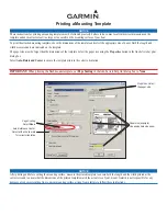
GMR 404
Brand: Garmin Pages: 26
GMR 18
Brand: Garmin Pages: 2

GMR 18
Brand: Garmin Pages: 2
GMR 404
Brand: Garmin Pages: 2
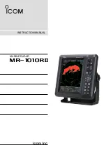
MR-1010RII
Brand: Icom Pages: 72
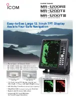
MR-1200RII
Brand: Icom Pages: 2
JMA-5212-4
Brand: Japan Radio Co. Pages: 20
JMA-7122-6XA
Brand: JRC Pages: 316
CSE 2800
Brand: Triax Pages: 24
EXPLORER 5075
Brand: COBHAM Pages: 72
Halo20
Brand: Simrad Pages: 32
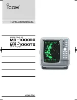
MR-1000R2
Brand: Icom Pages: 47
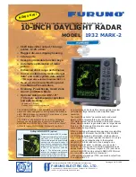
1932 MARK-2
Brand: Furuno Pages: 2

GMR 620 xHD2 Series
Brand: Garmin Pages: 8
GMR 404 xHD Open Array and Pedestal
Brand: Garmin Pages: 6

JMA-7100
Brand: JRC Pages: 8


