Honeywell HON 985B, Operating And Maintenance Instructions Manual
The Honeywell HON 985B is a high-quality, durable product. Ensure smooth operation and proper maintenance of this device by referring to the comprehensive Operating and Maintenance Instructions Manual. Download this manual for free from our website to gain expert guidance and make the most of your Honeywell HON 985B.
Share
Download


Reviews:
No comments
Related manuals for HON 985B

HS10
Brand: BakeMark Pages: 5

PB10
Brand: Fama Pages: 20

AM1
Brand: Rane Pages: 4

AM1
Brand: Rane Pages: 8
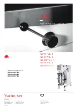
AR Series
Brand: Varimixer Pages: 16

GX300
Brand: Idex Pages: 29

V20
Brand: Varimixer Pages: 32

UT2204
Brand: Makita Pages: 7

UT1305
Brand: Makita Pages: 7

UT 1200
Brand: Makita Pages: 9

GM Series
Brand: Faggiolati Pumps Pages: 38
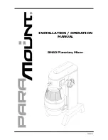
BM60
Brand: Paramount Fitness Pages: 17

950
Brand: Hamilton Beach Pages: 24

MX 1200 PRO
Brand: F.F. Group Pages: 36

BM10
Brand: Paramount Fitness Pages: 17
4400 Series
Brand: IED Pages: 10

W30
Brand: Varimixer Pages: 3

W80
Brand: Varimixer Pages: 29


