background image


HD-JC-010 

Network Keyboard


User Manual 

© 2011 Honeywell International Inc. All rights reserved. 

http://www.security.honeywell.com


Rev. A1 


Summary of Contents for HD-JC-010

Page 1: ...HD JC 010 Network Keyboard User Manual 2011 Honeywell International Inc All rights reserved http www security honeywell com Rev A1 ...

Page 2: ......

Page 3: ...yboard Function 4 Keyboard Appearance 4 Key Function List 5 Keyboards Ports 7 Port Features 8 Power 8 3 Menu Tree 10 Input Method 12 Log In 12 4 Menu Operation 13 Local Setup 13 Network Setup for network keyboard only 13 Time Setup 14 Address Setup 14 CTL Point 14 ID 15 Device Name 15 Device Type 15 Connection Type 15 Advanced 17 ...

Page 4: ...22 5 Keyboard Control DVR 23 Serial Port Connection 23 RS232 Serial Port Connection 23 Via RS485 Connection 23 Multi keyboard link via RS485 25 Network Connection 25 DVR and Keyboard Setup 27 DVR Setup 27 Keyboard Setup after Serial Port Connection 27 Keyboard Setup after Network Connection 29 Operation 29 Login 29 Logout 30 Record 30 PTZ Control and Image Color 30 Tour and Single Multiple Window ...

Page 5: ...2 Cable Connection 32 Keyboard Setup 32 Operation 33 Preset 34 Scan 35 Tour 35 PATTERN 38 7 Keyboard Upgrade 40 Keyboard Upgrade 40 8 Make COM Cable 42 Make RS232 COM Cable 42 Make RS485 COM Cable 42 25 pin Port and Switch Box Connection 43 ...

Page 6: ...verter 24 Figure 5 4 Multi Keyboard Link via RS485 25 Figure 5 5 Connection of Converter 25 Figure 5 6 Direct Connection via RS485 26 Figure 5 7 Connection via Hub 26 Figure 7 1 Update via Network 40 Figure 7 2 Select the Firmware 41 Figure 7 3 Update 41 Figure 8 1 Make RS232 Line 42 Figure 8 2 Make RS485 Line 43 Figure 8 3 Connection Between RS485 Converter and DVR 44 ...

Page 7: ...lease keep this operating manual well for future reference Tips You can refer to chapter 8 for COM cable connection information Important Safeguarding and Warnings All installation and operation should conform to your local electrical safety codes We assume no liability or responsibility for all the fires or electrical shock caused by improper handling or installation All the examination and repai...

Page 8: ...keys z Support keyboard lock function z Support multiple level operation rights z Support level link z Support single or multiple DVRs s menu setup z On screen menu user friendly procedure It is very easy for you to operate z Can control network video server and network video decoder z Support network ports connection z Can receive DVR alarm information support one channel activation on alarm z US...

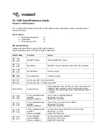
Page 9: ...Honeywell 3 Working Power 12VDC 1200mA LCD Dimension 84mm x 31 mm ...

Page 10: ... Appearance Function key There are three function keys SETUP ALARM SHIFT LCD Here is to display on screen menu Indication light There are six indication lights DVR DOME ALT COM ALARM POWER DVR function Here are operation keys for you to control DVR Public function Here includes ten numeral keys four direction keys ESC ENTER and ...

Page 11: ...dome Other indication light ALT Light turns on when connected with other devices Serial port indication light COM Light turns on when connected with serial port device Alarm indication light ALARM Light turns on when connected with alarm devices Indication light Power indication light POWER Light turns on when keyboard connected with power and works properly In single surveillance mode click Fn1 t...

Page 12: ...the previous video Next Play next video Reverse play frame by frame Reverse play frame by frame Character and numerals 0 9 Switch between numeral characters click Shift to switch Device ID ID Shortcut key to go to ID control point search Device channel number CAM Control DVR channel Cancel current operation Cancel ESC In playback mode click this key to go back to dynamic surveillance mode Confirm ...

Page 13: ...System pops up delete preset menu Iris zoom in TELE PTZ iris zooms in PTZ P T PTZ operation shortcut key Iris zoom out WIDE PTZ iris zooms out Focus zoom in NEAR PTZ focus zooms in Wiper WIPER Shortcut key to control dome wiper operation Focus zoom out FAR PTZ focus zooms out Lens zoom out CLOSE PTZ lens zoom out Lens zoom in OPEN PTZ lens zoom in Dome Matrix key function Light LIGHT Control dome ...

Page 14: ...nnect with one DVR You must use 485 232 converters to connect more DVRs RS 485 transmission distance is 1200 m 9600bps max 3000 m In level link mode one RS 485 port can connect with as many as 16 keyboards You can connect RJ45 with DVR and realize front device multiplex control via the network keyboard Power The keyboard uses 12V DC you can use 12V adapter included in the accessories package See F...

Page 15: ...Honeywell 9 Figure 2 3 Power Supply of the Keyboard ...

Page 16: ...Honeywell 10 3 Menu Tree Key board menu tree is shown as below ...

Page 17: ...int I D Device name Device type Connection type Password User management Default Empty point Version Date Connection type Point Information Menu operation Advance d Assistant System Info Control point Machine ID IP RS232 RS485 Alarm setup Language Backlight Network connectio n RS232 RS485 ...

Page 18: ...pitalized character z Small character Log In Plug in power socket power indication light is on You can see welcome information in LCD Click Enter or SETUP system pops up a dialogue box Now you can input user name and password The default user is admin password is 888888 2006 12 20 14 00 00 User name Password Network keyboard ...

Page 19: ...es the following items z Network setup z Time setup z Address setup Network Setup for network keyboard only Network setup is for you to input the following information z IP z Sub mask z Net gate z Port You can use left right key to highlight corresponding item and then input numeral Port 377 Sub Mask 255 255 255 000 Net Gate 192 168 000 001 IP ADD 192 168 000 118 ...

Page 20: ...SE 22 YY 2006 Mo 12 DD31 Address Setup Address value ranges from 0 to 255 Default factory setup is 0 When in level link mode 0 has the highest priority CTL Point CTL point includes the following items z ID z Device name z Device type z Connection type Network connection RS232 RS485 Address setting 0 ID 3 Connection type RS232 Dev name DVR 1 Dev Type DVR ...

Page 21: ...thods to give a name to the front device Device Type There are several options DVR dome matrix NVS You can use left right key to select Connection Type There are several options network RS232 RS485 You can use left right key to select corresponding connection type After you have selected connection type please click ENTER to go on connection setup Network When connection type is network click ENTE...

Page 22: ... information z 232ADD z PRTCL z Baud z D bit z O_E VFY z S bit RS485 When connection type is RS485 click ENTER key you can see an interface ask you to input the following information z 232ADD z PRTCL z Baud z D bit z O_E VFY z S bit D bit O_E VFY S Bit 485ADD O_E VFY None S Bit 1 PRTCL Baud 300 D bit 8 Baud 232ADD PRTCL ...

Page 23: ...sword Here is for you to modify password We recommend you input a six bit password including numeral and characters Administrator can modify password for all users Ordinary user can only modify login account password User Management User management is for administrator only Administrator can add delete or modify user set power for each user Ordinary user can only modify its own password and operat...

Page 24: ... BAK z Senior Confirm Pwer User c User Password Delete user You can select corresponding user and then click ENTER to delete Power setting Here you can select power for each user Use left and right key to highlight correspond right and click ENTER to confirm Icon means current user does not have this right Icon z means current user has current right In the following image current user is 1 and thi...

Page 25: ...c Empty Control Point Here is for you to delete all control point information Click ENTER to clear all Assistant Setup Assistant setup includes the following items Clear ALL CTL Point Yes ENTER No Esc Back light ON Alarm ON Language English Backlight Setup You can open LCD backlight It will last for ten minutes When you log in the next time backlight automatically turns on ...

Page 26: ...ference only z Date here is to display system released date for reference only z Connection type here is to display current connection type You can click ENTER to view type serial port or network z Point information Connection type Network Point Info 0 Version 1 10 Date 2006 12 29 Control Point You can input either of the following information to search one device System can automatically connect ...

Page 27: ... interface ID 3 is a dome and its RS232 address is 3 System automatically connects the dome Now you can use keyboard to control current dome Current Dev Dome RS232 3 ID 3 Note z When you use keyboard to control DVR please click ID and then click ESC to go back to previous menu z When you use keyboard to control other device click ESC to go back to previous menu Control point includes the following...

Page 28: ...hine and then click ENTER Here is for you to input machine name IP Address Use left right to highlight IP address and then click ENTER Here is for you to input device IP address RS232 Use left right to highlight RS232 and then click ENTER Here is for you to input RS 232 address RS485 Use left right key to highlight RS485 and then click ENTER Here is for you to input RS485 address ...

Page 29: ...ee Figure 5 1 DVR address number ranges from 1 to 255 please refer to DVR manual for more information Figure 5 1 RS232connection RS232 cable DVR Via RS485 Connection You can use one RS232 port can only connect with one DVR See Figure 5 2 You need to use RS 485 port once you want to control more than one DVRs You can user one standad RS485 to RS 232 box connect with DVR 232 port ...

Page 30: ...IN3 RS485 A line PIN4 RS485 B line PIN5 RS485 A line PIN6 RS485 B line You can use if you use RS485 connection via converter See Figure 5 3 Figure 5 3 Connect with RS485 Converter One 485 bus can connect with thirty two RS485 232 converters one RS485 232 converter can connect with twelve DVRs 485 232 converter A B 485 232 converter 485 232 converter ...

Page 31: ...ast converter on RS 485 port must be short circuited E g open converter See Figure 5 5 See the image below you need to change 1 2 short circuit to 2 3 short circuit Note Menu serial setup should conform to the device you connected otherwise keyboard can not control the device Figure 5 5 Connection of Converter Short circuit 1 2 3 Network Connection Connect RJ45 port to the network to realize netwo...

Page 32: ...re 5 6 for direct connection information Figure 5 6 Direct Connection via RS485 2 Connect via HUB Please refer to the following figure if you are connecting via the hub See Figure 5 7 Figure 5 7 Connection via Hub Crossover cable Switch Straight through cable ...

Page 33: ...ing to RS232 See Figure 5 8 The default setup is shown as below z Function network keyboard z Baud rate 9600 z Data bit 8 z Stop bit 1 z Parity none Please note keyboard setup should conform to DVR setup Keyboard Setup after Serial Port Connection In menu go to control point setup Here you need to input the following information ...

Page 34: ... left right key to select device type and then click up down to go on setup z Connection type Please use up down to highlight connection type and then use left right to select type Click ENTER to set the following items z 232 address z Parity z Protocol z Stop bit z Baud rate z Data bit Data bit 8 Baud rate 9600 Protocol DH2 Stop bit 1 232 Add 8 Parity None Note 232 address and 485 address are cor...

Page 35: ...up click ESC to exit System pops up the dialogue box to prompt you save setup CTL port 3777 Protocol DH 2 Save data YES ENTER NO ESC CTL point IP 192 168 090 111 Operation Login You can use the following ways to login ID device name IP 232 address 485 address Click ENTER to go to setup interface input you information and click ENTER to begin search System automatically begin login if search is OK ...

Page 36: ...ick P T in the keyboard to go to DVR control menu Tour and Single Multiple Window Switch Note before click tour key please make sure your current series DVR supports tour function You can click tour key 3 to begin touring F are corresponding to One four nine sixteen window display modes You can click numeral key to go to corresponding channel E g you can click numeral 1 to go to channel one For ch...

Page 37: ...number z After setup please click ENTER Network keyboard sends search results to DVR You can see the following interface if there are matched results NO 1 0 08 30 01 09 30 30 NO 1 1 09 30 01 10 30 00 NO 1 2 10 30 00 11 30 00 NO 1 3 11 30 00 12 30 00 NO 1 4 12 30 00 13 30 00 Download NO X file z Please use up down to select one path to save video files X here range from 0 to 4 Click ENTER to save v...

Page 38: ...ard menu go to control point Here you can input ID device name You can use left right key to select device type Use up down to highlight connection type then click ENTER to go to RS 485 setup 485 address is 1 default protocol is DH SD You can select in accordance with you actual demands After all the setup click Enter to save setup or you can click ESC to exit without saving the modification you h...

Page 39: ...lick MENU the image is shown as below The menu here should work with dome menu ID 0 1 up 5 Previous menu 2 down 6 Next menu 3 Left 7 Confirm 4 Right 8 Exit Current device Dome RS485 ADD 1 Speed It is to control direction The value ranges from one to eight Please use the number buttons of the keyboard to input value between 0 8 and press ENTER to confirm Operation here is only active with key press...

Page 40: ...oom out and anti clockwise is to zoom in Remove Preset Preset setup After zoom and PTZ setup input value and click ENTER to confirm Now you have set one preset GOTO Move cursor to highlight GOTO Preset setup Value 1 GOTO Remove Input preset value and click ENTER System goes to specified preset REMOVE Move cursor to highlight REMOVE Input preset value and click ENTER Now you have removed one preset...

Page 41: ...mit Versatile scan Right limit Random scan Speed Scan operation Use up down to highlight scan Input scan value and click ENTER to begin scanning Use left right keys to highlight stop Click ENTER to stop scanning Scan Value 1 Scan setup Begin Versatile scan Stop Random scan Note for versatile scan and random scan you need corresponding protocols to support Tour Tour setup Use up down keys to highli...

Page 42: ...click ENTER Now you have added tour point 3 to tour group 1 You can repeat the above procedures to add more tour point Add to tour Tour Remove tour Tour Value 1 Tour setup Speed Add to tour Duration Remove tour Remove tour group Tour Tour setup Tour group 1 Add to tour Stop Remove tour Tour Value 1 Tour setup Start Tour operation Speed Please use up down keys to highlight tour setup When cursor is...

Page 43: ... to highlight remove tour and then input corresponding value Click ENTER to delete current tour Add to tour Duration Remove tour Remove tour group Tour Tour setup Tour group 1 Add to tour point Tour point Remove tour point Tour Value 1 Tour setup Speed Remove tour point Move cursor to highlight tour group and then input corresponding value Please click Enter to confirm all the operation below is a...

Page 44: ...t Maximally support five paths Click ENTER to confirm Move cursor to highlight start and then input pattern value Now click ENTER to confirm Pattern Value 1 Patter setup Start Rotation Stop Move cursor to highlight stop Input pattern value and click ENTER to stop pattern Dome will automatically memorize all the operations you have done Pattern Value 1 Pattern setup Start Rotation Stop Pattern oper...

Page 45: ...Honeywell 39 Pattern Value 1 Pattern setup Start Pan rotation Stop Speed ...

Page 46: ...e return value TTL should be less than 255 Please download upgrade file to your local PC You can download upgrade file from our website or from our local service engineer Double click RECUpgrade exe to begin upgrade See Figure 7 1 Figure 7 1 Update via Network Please input network keyboard IP address and port Then click open files button to select upgrade file See Figure 7 2 ...

Page 47: ...button to begin upgrade System pops up upgrade process bar for your reference After successful upgrade click OK to finish operation See Figure 7 3 Tips Use you mouse to click the upgrade file drag it to the open files column and then release You can see the file path and current file is open System pops up alert information if it is not keyboard upgrade file Figure 7 3 Update ...

Page 48: ...t z One 25 pin DB25 z One 485 transmission box Including one power source Make RS232 COM Cable Please refer to the following figure for RS232 port information See Figure 8 1 Figure 8 1 Make RS232 Line RS232 serial port RS232serial port DB9 DB9 Make RS485 COM Cable You can refer to Figure 8 2 if you are connecting the keyboard with the switcher box ...

Page 49: ...IN4 RS485 B line PIN5 RS485 A line PIN6 RS485 B line 25 pin Port and Switch Box Connection Connect switch 25 pin box RS232 port with DVR RS232 port 25 pin outlet supports maximum twelve RS232 ports Switch is just for sending not for receiving So you can use two cables GND and TXD Please refer to the following sheet if you are connecting 485 switch box to DVR See Figure 8 3 ...

Page 50: ...rt to connect keyboard with DVR Note z This manual is for reference only Slight difference may be found in the user interface z All the designs and software here are subject to change without prior written notice z If there is any uncertainty or controversy please refer to the final explanation of ours z Please visit our website for more information ...

Page 51: ...ad Shanghai 200051 China TEL 86 21 22196888 FAX 86 21 62370740 Honeywell Security China Co Ltd Block 28 Section 2 Huai De Cui Gang Industrial Estate Fu Yong Bao An Shenzhen P R China TEL 86 0755 27326500 FAX 86 0755 27391736 2011 Honeywell International Inc http www security honeywell com ...

Reviews: