


® U.S. Registered Trademark
Copyright © 2002 Honeywell •
•All Rights Reserved
INSTALLATION INSTRUCTIONS
69-1341EF
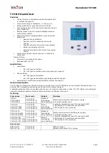
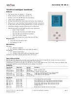
H8908B Humidistat
H8908C Dehumidistat
APPLICATION
The H8908B Humidistat and H8908C Dehumidistat
(humidity controllers) provide automatic low voltage
control of humidifiers and dehumidifiers or ventilators,
respectively, in central heating and air conditioning
systems. They have a spst, snap-acting, dust-proof
switch and are designed for wall or surface duct
mounting.
INSTALLATION
When Installing this Product...
1.
Read these instructions carefully. Failure to follow
them could damage the product or cause a hazard-
ous condition.
2.
Check the ratings given in the instructions and on
the product to make sure the product is suitable for
your application.
3.
Installer must be a trained, experienced service
technician.
4.
After installation is complete, check out product
operation as provided in these instructions.
CAUTION
Personal Injury Hazard.
Power supply can cause electrical shock.
Disconnect power supply before beginning
installation.
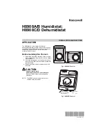
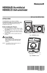
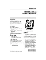
Location and Mounting
The styling of the H8908 is designed to blend with the
latest T8600 family of Honeywell Chronotherm® IV
Deluxe Programmable Thermostats. A mounting
template is included for mounting the H8908 next to the
T8600. The H8908 can also be mounted at any other
convenient location in the living area or equipment room.
See Fig 1.
NOTE: The H8908 electrical connections are not
shared with the thermostat.
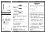
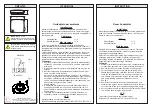
Fig. 1. H8908B Humidistat.
Wall Mounting
IMPORTANT
Mount the control in an area with average room
temperature and average relative humidity.
The following mounting instructions are for mounting the
H8908 on the wall next to the T8600. When installing the
H8908 at another location, modify the procedure to fit the
installation.
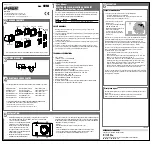
1.
Hold the mounting template (included) next to the
T8600. Select the mounting side for the H8908.
The template is reversible for mounting on either
the left or right side of the T8600. See Fig. 2.
2.
Mark the holes for the two mounting screws
(included). Then mark the hole for the low voltage
wiring on the template that corresponds with the
side selected in step 1.
3.
Remove the template and drill the holes.
4.
Run low voltage wiring to the location and pull
about 6 in. (152 mm) of wire through the hole.
5.
Plug the hole with nonflammable insulation to pre-
vent drafts from affecting the control operation.
6.
Remove the H8908 case from the base. See
Fig. 1.
7.
Position the base on the wall with the arrow up.
Humidity Control
Régulateur d'humidité
-20
°
F
-10
°
F
0
°
F
+10
°
F
+20
°
F
Over 20
°
F
15%
20%
25%
30%
35%
40%
HUMIDITY
SETTING
OUTDOOR
TEMPERATURE
-30
°
C
-25
°
C
-20
°
C
-10
°
C
-5
°
C
Over 0
°
C
M13371
CASE REMOVAL
SLOT
HOLE FOR WIRING
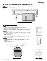
THE DUCT MOUNTING
INSTALLATIONS