INSTALLATION INSTRUCTIONS
Place Bar Code Here
69-1341EF-07
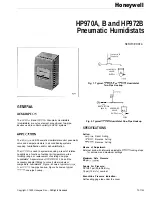
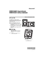
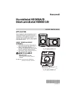
H8908A/B Humidistat;
H8908C/D Dehumidistat
APPLICATION
The H8908 family of low-voltage humidistats/
dehumidistats provide accurate control of whole house
humidifiers, dehumidifiers, and ventilators. They have a
snap-acting, dust-proof SPST switch and can be
mounted to a duct or wall.
Before Installing this Product...
1.
Read these instructions carefully. Failure to follow
them could damage the product or cause a hazard-
ous condition.
2.
Check the ratings given in the instructions and on
the product to make sure the product is suitable for
your application.
3.
Installer must be a trained, experienced service
technician.
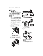
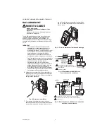
CAUTION
Personal Injury Hazard.
Power supply can cause electrical shock.
Disconnect power supply before beginning
installation.
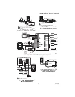
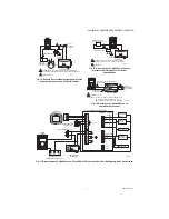
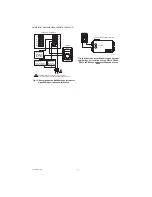
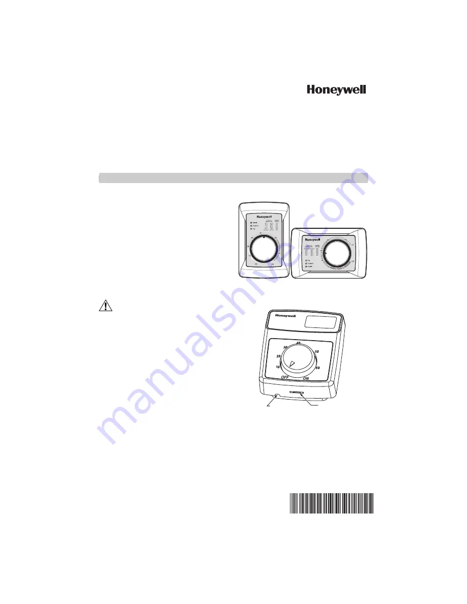
NOTE: The H8908 electrical connections are not
shared with the thermostat.
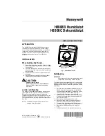
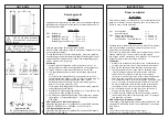
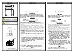
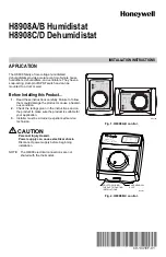
Fig. 1. H8908A,D control.
Fig. 2. H8908B,C control.
M24726
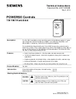
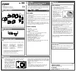
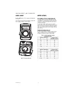
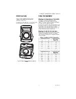
Humidity Control
Régulateur d'humidité
-20 F
-10 F
0 F
+10 F
+20 F
Over 20 F
15%
20%
25%
30%
35%
40%
HUMIDITY
SETTING
OUTDOOR
TEMPERATURE
-30 C
-25 C
-20 C
-10 C
-5 C
Over 0 C
M13371
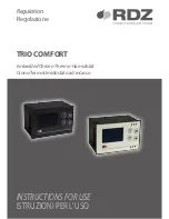
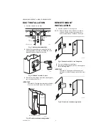
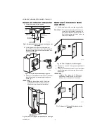
CASE REMOVAL
SLOT
HOLE FOR WIRING
THE DUCT MOUNTING
INSTALLATIONS